
Related Manuals for Emerson Rosemount 1208A


Summary of Contents for Emerson Rosemount 1208A
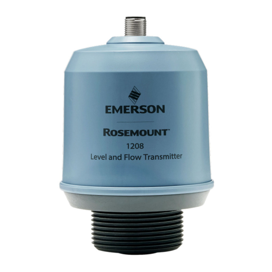
- Page 1 Reference Manual 00809-0100-7062, Rev AB October 2022 ™ Rosemount 1208A Level and Flow Transmitter Non-Contacting Radar...
- Page 2 • 1-800-654-7768 (24 hours a day — includes Canada) • Outside of these areas, contact your local Emerson representative. WARNING Failure to follow safe installation and servicing guidelines could result in death or serious injury. Ensure the transmitter is installed by qualified personnel and in accordance with applicable code of practice.
-
Page 3: Table Of Contents
Reference Manual Contents 00809-0100-7062 October 2022 Contents Chapter 1 Introduction......................5 1.1 Using this manual........................5 1.2 Product certifications........................5 1.3 Open source licenses........................5 1.4 Product recycling/disposal......................5 Chapter 2 Transmitter overview....................7 2.1 Measurement principle........................ 7 2.2 Process characteristics......................... 7 2.3 Vessel characteristics........................8 2.4 Non-contacting radar technology.................... - Page 4 A.4 Dimensional drawings....................... 77 Appendix B Configuration parameters..................80 B.1 Menu tree..........................80 B.2 Basic setup..........................81 B.3 Digital output..........................82 B.4 Analog output........................... 84 B.5 Geometry..........................86 B.6 Volume flow..........................88 B.7 Advanced setup......................... 89 Rosemount 1208A Level and Flow Transmitter...
-
Page 5: Chapter 1 Introduction
Configuration parameters provides extended information about the configuration parameters. Product certifications See the Rosemount 1208A Product Certifications document for detailed information on the existing approvals and certifications. Open source licenses This device uses open source software. Further information can be found in the License Information document available at Emerson.com/Rosemount. - Page 6 Introduction Reference Manual October 2022 00809-0100-7062 Rosemount 1208A Level and Flow Transmitter...
-
Page 7: Chapter 2 Transmitter Overview
A. Frequency (GHz) B. Time (s) C. Transmitted signal D. Reflected signal The Rosemount 1208A can also calculate the volume flow rate in an open channel. Process characteristics 2.2.1 Dielectric constant A key parameter for measurement performance is reflectivity. A high dielectric constant of the media provides better reflection and enables a longer measuring range. -
Page 8: Vessel Characteristics
The Rosemount 1208A uses Frequency Modulated Continuous Wave (FMCW) technology and smart algorithms to maximize measurement accuracy and reliability, even in small tanks and challenging fast-filling vessels. - Page 9 Reference Manual Transmitter overview 00809-0100-7062 October 2022 2.4.1 Application examples Storage tanks Gain insights into your tank and ensure production runs smoothly without interruption. Plastic tanks Monitor the inventory of your small and medium sized plastic tanks by measuring through the plastic roof.
-
Page 10: Components Of The Transmitter
Transmitter overview Reference Manual October 2022 00809-0100-7062 Open channel flow Use the Rosemount 1208A for volume flow measurement of water and wastewater in open channels. Components of the transmitter Figure 2-2: Components A. M12 male connector (A-coded) B. Transmitter housing C. - Page 11 Reference Manual Transmitter overview 00809-0100-7062 October 2022 unshielded standard cables using standard connectors such as M12. Process data, events and parameters are transferred to the master via IO-Link. The IO-Link master then transfers the data to the controller (PLC) and its fieldbus or industrial ethernet network. Figure 2-3: Example of an IO-Link System A.
- Page 12 Transmitter overview Reference Manual October 2022 00809-0100-7062 Rosemount 1208A Level and Flow Transmitter...
-
Page 13: Chapter 3 Mechanical Installation
Reference Manual Mechanical installation 00809-0100-7062 October 2022 Mechanical installation Safety messages Instructions and procedures in this section may require special precautions to ensure the safety of the personnel performing the operations. Information that potentially raises safety issues is indicated by a warning symbol ( ). - Page 14 Do not mount the transmitter on a manway cover. • Do not position the transmitter directly over a side manway door. • Multiple Rosemount 1208A transmitters can be used in the same tank without interfering with each other. Figure 3-1: Recommended Mounting Position 3.2.2...
- Page 15 Reference Manual Mechanical installation 00809-0100-7062 October 2022 3.2.3 Inclination The transmitter should be mounted vertically to ensure a good echo from the product surface. See Figure 3-3 for recommended maximum inclination. Figure 3-3: Inclination Max. 3° 90° 3.2.4 Non-metallic tanks Nearby objects outside the tank may cause disturbing radar echoes.
- Page 16 0.9 ft. (0.3 m) 13.1 ft. (4 m) 1.8 ft. (0.6 m) 19.7 ft. (6 m) 2.8 ft. (0.8 m) 26.2 ft. (8 m) 3.7 ft. (1.1 m) 32.8 ft. (10 m) 4.7 ft. (1.4 m) Rosemount 1208A Level and Flow Transmitter...
- Page 17 Reference Manual Mechanical installation 00809-0100-7062 October 2022 3.2.6 Nozzle requirements To allow the microwaves to propagate undisturbed, the nozzle dimensions should be kept within the specified limits as given in Table 3-3. The inside of the nozzle must be smooth (i.e.
-
Page 18: Bracket Mounting
Mechanical installation Reference Manual October 2022 00809-0100-7062 Bracket mounting 3.3.1 Mount the standard bracket Procedure 1. Mount the bracket on the pipe/ceiling/wall. On pipe: 13 mm On ceiling/wall: Rosemount 1208A Level and Flow Transmitter... - Page 19 Reference Manual Mechanical installation 00809-0100-7062 October 2022 2. Ensure the adjustable holder is directed toward the ground. 90° 3. Install and hand tighten the transmitter. Related information Bracket hole pattern Reference Manual...
- Page 20 Mechanical installation Reference Manual October 2022 00809-0100-7062 3.3.2 Mount the extendable bracket Procedure 1. Mount the bracket on the pipe/wall. On pipe: 13 mm On wall: Rosemount 1208A Level and Flow Transmitter...
- Page 21 Reference Manual Mechanical installation 00809-0100-7062 October 2022 2. Mount the extendable arm. Do not fully tighten the screws at this stage. 3. Install and hand tighten the transmitter. Reference Manual...
- Page 22 Mechanical installation Reference Manual October 2022 00809-0100-7062 4. Connect the M12 cable. 5. Ensure the adjustable holder is properly aligned. Rosemount 1208A Level and Flow Transmitter...
- Page 23 Reference Manual Mechanical installation 00809-0100-7062 October 2022 6. Fold down the arm to a horizontal position. 7. Adjust the length of the arm as necessary. Then tighten the two screws. Reference Manual...
- Page 24 8. Check that the bracket installation is level. To raise or lower the arm, adjust the two level screws. Then tighten the two nuts. 10 mm 9. Tighten the two screws. Related information Bracket hole pattern Rosemount 1208A Level and Flow Transmitter...
-
Page 25: Installing On A Tank
Reference Manual Mechanical installation 00809-0100-7062 October 2022 Installing on a tank 3.4.1 Mount the flange Procedure 1. Place a suitable gasket on the tank flange. 2. Place the flange over the gasket. 3. Tighten the bolts and nuts with sufficient torque for the flange and gasket choice. 4. - Page 26 Mount the NPT threaded adapter Procedure 1. Apply appropriate thread sealant to the outer threads. 2. Mount the threaded adapter on the tank. 60 mm 3. Apply appropriate thread sealant to the transmitter threads. Rosemount 1208A Level and Flow Transmitter...
- Page 27 Reference Manual Mechanical installation 00809-0100-7062 October 2022 4. Install and hand tighten the transmitter. Reference Manual...
- Page 28 Mechanical installation Reference Manual October 2022 00809-0100-7062 Rosemount 1208A Level and Flow Transmitter...
-
Page 29: Chapter 4 Electrical Installation
Reference Manual Electrical installation 00809-0100-7062 October 2022 Electrical installation Safety messages Instructions and procedures in this section may require special precautions to ensure the safety of the personnel performing the operations. Information that potentially raises safety issues is indicated by a warning symbol ( ). - Page 30 OUT2 OUT1/IO-Link Table 4-1: Pin Assignment Wire color Signal Brown 24 V White OUT2 Digital output or active 4-20 mA analog output Blue Black OUT1/IO-Link Digital output or IO-Link mode According to IEC 60947-5-2. Rosemount 1208A Level and Flow Transmitter...
- Page 31 Reference Manual Electrical installation 00809-0100-7062 October 2022 Figure 4-2: Example Circuits 2: OUT2 4: OUT1 2: OUT2 4: OUT1 2: OUT2 4: OUT1 2: OUT2 4: OUT1 A. 2 x Digital output PnP B. 2 x Digital output NpN C. 1 x Digital output PnP / 1 x Analog output D.
-
Page 32: Power Up Transmitter
Power up transmitter Procedure Verify the power supply is disconnected. 2. Insert the M12 connector and screw tight. See the manufacturer’s instruction manual for recommended torque. 3. Connect the power supply. Related information Ingress protection Rosemount 1208A Level and Flow Transmitter... -
Page 33: Chapter 5 Configuration
Reference Manual Configuration 00809-0100-7062 October 2022 Configuration Safety messages Instructions and procedures in this section may require special precautions to ensure the safety of the personnel performing the operations. Information that potentially raises safety issues is indicated by a warning symbol ( ). -
Page 34: Get Started With Your Preferred Configuration Tool
The Rosemount IO-Link Assistant software checks and lets you download the latest IODDs for your device catalog. Prerequisites For an online update, an internet connection is required. Procedure 1. Click the icon. The Device description files (IODD): download and install window opens. Rosemount 1208A Level and Flow Transmitter... - Page 35 An IODD DTM Interpreter is required to integrate IODDs into an FDT/DTM environment (e.g PACTware). Prerequisites The IODD DTM Interpreter is usually included in the FDT/DTM software installation package. It can also be downloaded from Emerson.com/Rosemount1208A. Procedure 1. Start the IODD DTM Interpreter software. Reference Manual...
-
Page 36: Perform The Basic Setup
2. In the Engineering Units list, select Metric or Imperial. 3. Select Write to device. Related information Engineering units 5.5.2 Enter the reference height Procedure 1. Under Menu, select Parameter → Basic Setup. 2. Enter the Reference Height. 3. Select Write to device. Rosemount 1208A Level and Flow Transmitter... - Page 37 Reference Manual Configuration 00809-0100-7062 October 2022 Related information Reference height 5.5.3 Configure the analog output The transmitter can be set to output the level or volume flow as a 4-20 mA signal. Procedure 1. Under Menu, select Parameter → OUT2 Analog Output. 2.
- Page 38 Reference Manual October 2022 00809-0100-7062 • Linearization table • Parshall flume • Khafagi-Venturi flume 3. Select Volume Flow Table/Formula, and then set the parameters as desired. 4. Select Write to device. Related information Volume flow Rosemount 1208A Level and Flow Transmitter...
-
Page 39: Operation And Maintenance
Reference Manual Operation and maintenance 00809-0100-7062 October 2022 Operation and maintenance Safety messages Instructions and procedures in this section may require special precautions to ensure the safety of the personnel performing the operations. Information that potentially raises safety issues is indicated by a warning symbol ( ). - Page 40 A value that triggers an alert, such as a high or low temperature indication, will change the overall status of the device, but the measurement might still be indicated as “Good” if the reliability of the data is good. Rosemount 1208A Level and Flow Transmitter...
-
Page 41: Enter The Demonstration Mode
Reference Manual Operation and maintenance 00809-0100-7062 October 2022 Enter the demonstration mode In this mode, the signal processing method is optimized for demo situations when simulating a product surface with, for example, a measurement target plate. Note This mode is intended for demonstration purposes only, and should not be used for normal operations. - Page 42 Operation and maintenance Reference Manual October 2022 00809-0100-7062 Rosemount 1208A Level and Flow Transmitter...
-
Page 43: Service And Troubleshooting
Reference Manual Service and troubleshooting 00809-0100-7062 October 2022 Service and troubleshooting Safety messages Instructions and procedures in this section may require special precautions to ensure the safety of the personnel performing the operations. Information that potentially raises safety issues is indicated by a warning symbol ( ). -
Page 44: Diagnostic Messages
The software has detected an internal error. Recommended actions 1. Restart the device. 2. Restore default settings and reconfigure the device. 3. If the condition persists, replace the device. Related information Perform a device reset Restore to factory settings Rosemount 1208A Level and Flow Transmitter... - Page 45 Reference Manual Service and troubleshooting 00809-0100-7062 October 2022 7.2.3 General power supply fault Alarm classification Event General power supply fault – Check availability Device status Failure Class Error Possible cause Power supply drops below 18 Vdc during transmitter start-up. Recommended actions Verify voltage is 18-30 Vdc at the transmitter terminal.
- Page 46 The device is in simulation mode and is not reporting actual information. Recommended actions 1. If this behavior is not desired, stop simulation mode. 2. If the condition persists, restart the device. Related information Use the simulation mode Perform a device reset Rosemount 1208A Level and Flow Transmitter...
- Page 47 Reference Manual Service and troubleshooting 00809-0100-7062 October 2022 7.2.7 Level measurement lost Alarm classification Event Level measurement lost – Check application Device status Failure Class Error Possible cause No valid level reading. Reasons may be multiple: • No valid surface echo peak in the measuring range •...
- Page 48 Device status Out of specification Class Warning Possible cause The electronics temperature is outside the operating range. Recommended actions 1. Verify ambient temperature is within the operating range. 2. Insulate device. Related information Ambient temperature Rosemount 1208A Level and Flow Transmitter...
- Page 49 Reference Manual Service and troubleshooting 00809-0100-7062 October 2022 7.2.10 Short circuit Alarm classification Event Short circuit – Check installation Device status Out of Specification Class Error Possible cause Short circuit on the digital output. Recommended actions Check cable and connections. 7.2.11 Primary supply voltage over-run Alarm classification...
- Page 50 Frequent writing of parameters from master to device. Recommended actions 1. Check the master configuration. 2. Restart the device. 3. If error persists, contact your local Emerson representative. Related information Perform a device reset Rosemount 1208A Level and Flow Transmitter...
- Page 51 Reference Manual Service and troubleshooting 00809-0100-7062 October 2022 7.2.15 Measurement range over-run Alarm classification Event Measurement range over-run – Check application Device status Out of Specification Class Error Possible cause The level measurement is outside the configured range for the volume flow. Recommended actions Ensure that level values within operating range are included in the volume flow table.
-
Page 52: Troubleshooting Incorrect Level Readings
Reference Height). • Analyze the Echo Peaks and check General Threshold. • Restore default settings and reconfigure the device. Related information Reference height Analyze the echo peaks Adjust the general threshold Restore to factory settings Rosemount 1208A Level and Flow Transmitter... - Page 53 Reference Manual Service and troubleshooting 00809-0100-7062 October 2022 7.3.2 Level is stuck in measuring range Figure 7-2: Symptom A. Level B. Time C. Actual level D. Reported level Possible cause Disturbing object in the tank. Recommended actions • Analyze the Echo Peaks and check General Threshold. •...
- Page 54 Move the transmitter to another position. Possible cause Product build-up on the antenna. Recommended actions • Clean the antenna. Related information Analyze the echo peaks Adjust the general threshold Change the upper null zone Mounting position Rosemount 1208A Level and Flow Transmitter...
- Page 55 Reference Manual Service and troubleshooting 00809-0100-7062 October 2022 7.3.4 Level value drops when close to antenna Symptom Level value drops to a lower value when product surface is close to antenna. Figure 7-4: Symptom A. Level B. Time C. Actual level D.
- Page 56 Figure 7-5: Symptom A. Level B. Time C. Reported level Possible cause Excessive foaming or turbulence. Recommended actions • Under turbulent conditions with low level rates, consider increasing the Damping value. Related information Damping value Rosemount 1208A Level and Flow Transmitter...
- Page 57 Reference Manual Service and troubleshooting 00809-0100-7062 October 2022 7.3.6 Measured level is occasionally unstable Figure 7-6: Symptom A. Level B. Time C. Actual level D. Reported level Possible cause The product surface is close to a suppressed false echo. Recommended actions •...
- Page 58 D. Reported level Possible cause Damping value is set too high. Recommended actions • If there is a problem with lag during rapid level changes, consider decreasing the Damping value. Related information Damping value Rosemount 1208A Level and Flow Transmitter...
- Page 59 Reference Manual Service and troubleshooting 00809-0100-7062 October 2022 7.3.8 Incorrect level at 100% (20 mA) Symptom Measured level is correct at 0% (4 mA) but incorrect at 100% (20 mA). Figure 7-8: Symptom A. Level B. Time C. Actual level D.
- Page 60 B. Time C. Actual level D. Reported level Possible cause A strong double bounce echo is interpreted as the product surface. Recommended actions • Move the transmitter to another position. Related information Mounting position Rosemount 1208A Level and Flow Transmitter...
- Page 61 Reference Manual Service and troubleshooting 00809-0100-7062 October 2022 7.3.10 Dropping of level close to tank bottom Symptom Measured value drops to zero level in the tank bottom region. Figure 7-10: Symptom A. Level B. Time C. Actual level D. Reported level Possible cause Transmitter has locked on a strong tank bottom echo.
- Page 62 Recommended actions • Before opening the manway cover, disconnect power to the transmitter. • After closing, restart the device. • Move the transmitter to another position. Related information Mounting position Perform a device reset Rosemount 1208A Level and Flow Transmitter...
- Page 63 Reference Manual Service and troubleshooting 00809-0100-7062 October 2022 7.3.12 Level measurement is lost in an empty tank Symptom The transmitter reports "Level measurement lost" in an empty tank after closing the side manway door. Figure 7-12: Symptom A. Level B. Time C.
-
Page 64: Managing Disturbance Echoes
There are two general methods for managing disturbance echoes: • Set general threshold to filter out weak disturbance echoes and noise. • Increase the Upper Null Zone to block out disturbance echoes at the top of the tank. Rosemount 1208A Level and Flow Transmitter... - Page 65 Reference Manual Service and troubleshooting 00809-0100-7062 October 2022 7.4.1 Adjust the general threshold If necessary, the general threshold value can be increased if a disturbance echo is interpreted as the product surface. Alternatively, a lower threshold may be required to handle weak surface echoes (e.g.
-
Page 66: Service And Troubleshooting Tools
It is possible to set the level to a simulated value for testing purposes. The simulated value affects both digital and analog output. Procedure 1. Under Menu, select Parameter → Service Tools → Simulation. Rosemount 1208A Level and Flow Transmitter... -
Page 67: Service Support
Measure the analog output with the ampere meter and verify it is within 20±0.01 mA. 4. Select Exit Fixed Current Mode. Service support To expedite the return process, refer to Emerson.com and contact the nearest Emerson representative. Reference Manual... - Page 68 Returned products must include a copy of the required Safety Data Sheet (SDS) for each substance. Emerson representatives will explain the additional information and procedures necessary to return goods exposed to hazardous substances.
-
Page 69: Appendix A Specifications And Reference Data
Reference Manual Specifications and reference data 00809-0100-7062 October 2022 Specifications and reference data Performance specifications A.1.1 General Reference conditions • Measurement target: Stationary metal plate, no disturbing objects • Temperature: 59 to 77 °F (15 to 25 °C) • Ambient pressure: 14 to 15 psi (960 to1060 mbar) •... - Page 70 Radio Equipment Directive (2014/53/EU) and Radio Equipment Regulations (S.I. 2017/1206): — ETSI EN 302 372 — ETSI EN 302 729 — EN 62311 • Part 15 of the FCC Rules • Industry Canada RSS 211 Rosemount 1208A Level and Flow Transmitter...
-
Page 71: Functional Specifications
Reference Manual Specifications and reference data 00809-0100-7062 October 2022 Related information Product certifications Functional specifications A.2.1 General Field of application Continuous measurement of level and open channel flow. Minimum dielectric constant Measurement principle Frequency Modulated Continuous Wave (FMCW) Frequency range 77 to 81 GHz Maximum output power 3 dBm (2 mW) - Page 72 Maximum loop resistance is determined by the voltage level of the external power supply: Maximum Loop Resistance = 43.5 × (External Power Supply Voltage - 18) + 600 Ω Figure A-2: Load Limits 1200 1121 1100 1000 A. Loop Resistance (Ω) B. External Power Supply Voltage (Vdc) Rosemount 1208A Level and Flow Transmitter...
- Page 73 Reference Manual Specifications and reference data 00809-0100-7062 October 2022 Analog signal on alarm The transmitter automatically and continuously performs self-diagnostic routines. If a failure or a measurement error is detected, the analog signal will be driven offscale to alert the user. High or low failure mode is user-configurable. Table A-1: Signal on Alarm Level Custom levels...
- Page 74 Volume flow calculations • Linearization table • Parshall flume • Khafagi-Venturi flume A.2.7 Process pressure -15 to 43.5 psig (-1 to 3 bar) Note The PE100 flanges must be used only in non-pressurized applications. Rosemount 1208A Level and Flow Transmitter...
-
Page 75: Physical Specifications
Emerson is not in a position to evaluate or guarantee the compatibility of the process fluid or other process parameters with the product, options, configuration, or materials of construction selected. - Page 76 Material exposed to tank atmosphere • Antenna and housing: PVDF • Gasket: EPDM or FKM GLT • Flange: PE100, 316/316L, or 1.4404 • Threaded adapter: 316/316L/1.4404 IP68 at 9.8 ft. (3 m) for more than 30 minutes. Rosemount 1208A Level and Flow Transmitter...
-
Page 77: Dimensional Drawings
Reference Manual Specifications and reference data 00809-0100-7062 October 2022 Dimensional drawings Related information Type 1 Drawing A.4.1 Transmitter Figure A-3: Rosemount 1208A Ø 3.11 (79) 4.84 3.86 (123) (98) 0.79 (20) 0.13 (3) A. NPT 1½-in. or ISO 228/1-G1½-in. thread B. - Page 78 Dimensions are in inches (millimeters). Figure A-6: Extendable Version A. For 1- to 2-in. nominal pipe sizes; 2-in. pipe is the recommended size B. Adjustable length: 17.5 to 28.9 in. (445 to 735 mm) Rosemount 1208A Level and Flow Transmitter...
- Page 79 Reference Manual Specifications and reference data 00809-0100-7062 October 2022 Bracket hole pattern Figure A-7: Hole Pattern for Wall Mounting 3.23 (82) Ø 0.28 (7) 2.44 (62) Dimensions are in inches (millimeters). Reference Manual...
-
Page 80: Appendix B Configuration Parameters
Volume Flow Table/Formula Service Tools Application Mode Maintenance Device Reset Restore Factory Settings Simulation Analog Out Calibration Advanced Setup Measurement Recovery Time Damping Value General Threshold * Contains the same sub-menus as OUT1 Digital Output. Rosemount 1208A Level and Flow Transmitter... -
Page 81: Basic Setup
Reference Manual Configuration parameters 00809-0100-7062 October 2022 Basic setup B.2.1 Engineering units Sets the unit of measure for length, temperature, and volume flow. Option Length unit Temperature unit Volume flow unit Metric °C Imperial inch °F US gal/h After appropriate units have been selected, all configuration parameters and transmitter variables will be expressed in these units. -
Page 82: Digital Output
Figure B-3: Example - High Alarm with Alarm Delays A. Level B. Time C. SP1 - High alarm set point D. SP1 - Hysteresis high alarm E. Alarm on delay F. Alarm off delay Rosemount 1208A Level and Flow Transmitter... - Page 83 Reference Manual Configuration parameters 00809-0100-7062 October 2022 Options for alarm on delay Table B-1: Alarm On Delay Option Description Always Alarm on delay is always used. Lost surface Alarm on delay is used only for lost surface alarms. This may be useful in applications when there are small and local rapid level changes caused by surface turbulence.
-
Page 84: Analog Output
Note The 20 mA point should be set below the reduced accuracy zone at the top of the tank. Rosemount 1208A Level and Flow Transmitter... - Page 85 Reference Manual Configuration parameters 00809-0100-7062 October 2022 Figure B-5: Example of Range Value Settings A. Reduced accuracy zone B. 100% (20 mA) C. Zero Level D. Level measurement range 0-100% E. 0% (4 mA) Related information Accuracy over measuring range B.4.3 Alarm mode The transmitter automatically and continuously performs self-diagnostic routines.
-
Page 86: Geometry
You can extend this value to block out disturbing echoes close to the antenna, for example from the tank nozzle. Note Make sure the 20 mA value is below the Upper Null Zone. Measurements are not performed within the Upper Null Zone (UNZ). Rosemount 1208A Level and Flow Transmitter... - Page 87 Reference Manual Configuration parameters 00809-0100-7062 October 2022 Figure B-7: Upper Null Zone A. Upper Null Zone B. Disturbance echo C. 100% (20 mA) D. General threshold E. Product surface echo Related information Change the upper null zone Bottom offset The Bottom Offset is defined as the distance between Zero Level and the tank bottom. The default value is zero.
-
Page 88: Volume Flow
The volume flow table is used to convert the measured level into a volume flow rate. Up to 30 level-volume flow pairs can be entered. The level points must be entered in increasing order. Rosemount 1208A Level and Flow Transmitter... -
Page 89: Advanced Setup
Reference Manual Configuration parameters 00809-0100-7062 October 2022 B.6.3 Volume flow formula Parshall Flume The volume flow is calculated from the formula: Q = K × H Table B-2: Parshall Flume Parameters Parameter Description Calculated volume flow in m Measured level in m Constant K Flume specific factor K Exponent n... - Page 90 The transmitter uses certain criteria to decide which type of echo peak that is detected. Only echoes above the general threshold might be considered the product surface. Figure B-9: Threshold Principle A. General threshold B. Product surface echo Related information Adjust the general threshold Rosemount 1208A Level and Flow Transmitter...
- Page 91 Reference Manual Configuration parameters 00809-0100-7062 October 2022 Reference Manual...
- Page 92 2022 Emerson. All rights reserved. Emerson Terms and Conditions of Sale are available upon request. The Emerson logo is a trademark and service mark of Emerson Electric Co. Rosemount is a mark of one of the Emerson family of companies. All other marks are the property...
Need help?
Do you have a question about the Rosemount 1208A and is the answer not in the manual?
Questions and answers