
Related Manuals for Emerson Rosemount 1152 Alphaline


Summary of Contents for Emerson Rosemount 1152 Alphaline
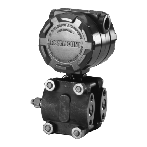
- Page 1 Reference Manual 00809-0100-4235, Rev BA April 2007 ® Rosemount 1152 Alphaline Nuclear Pressure Transmitter Product Discontinued www.emersonprocess.com/rosemount/nuclear...
- Page 2 IMPORTANT NOTICE -- ERRATA Model 1152 Product Manual 00809-0100-4235 Rev BA (April 2007) Affected Effect. Description of Change Pages Date Mounting Bracket – Carbon steel, AISI 1010 or JIS G3131 SPHC P/O with 3/13/09 polyurethane paint; or 316L SST. 1/24/11 Process Flange –CF3M (Cast version of 316L SST) 10/21/09 Drain/Vent Valves –316L SST...
- Page 3 00809-0100-4235, Rev BA Rosemount 1152 April 2007 ® Rosemount 1152 Alphaline Nuclear Pressure Transmitter NOTICE Read this manual before working with the product. For personal and system safety, and for optimum product performance, make sure you thoroughly understand the contents before installing, using, or maintaining this product.
- Page 4 Reference Manual 00809-0100-4235, Rev BA Rosemount 1152 April 2007 Rosemount Nuclear Instruments, Inc. Warranty and Limitations of Remedy NOTICE Authorization for return is required from Rosemount Nuclear Instruments, Inc. prior to shipment. Contact the Nuclear Instruments Group (952-949-5210) for details on obtaining Return Material Authorization (RMA). Rosemount Nuclear Instruments will not accept any returned material without a Returned Material Authorization.
- Page 5 Include errata sheet information on circuit board number changes: Replaced amplifier circuit card, P/N 01152-0125-0001 with 01152-0125-0002. Throughout Throughout References to Fisher-Rosemount were changed to Emerson Process Management i, back cover Cover, i & back cover Web address changed from www.rosemount.com to www.emersonprocess.com/rosemount/nuclear...
- Page 6 Reference Manual 00809-0100-4235, Rev BA Rosemount 1152 April 2007...
-
Page 7: Table Of Contents
Reference Manual 00809-0100-4235, Rev BA Rosemount 1152 April 2007 Table of Contents SECTION 1 Overview ..........1-1 About This Transmitter . - Page 8 Reference Manual 00809-0100-4235, Rev BA Rosemount 1152 April 2007 Zero and Span Adjustments ....... . 4-5 Current Controls .
-
Page 9: Overview
Reference Manual 00809-0100-4235, Rev BA Rosemount 1152 April 2007 Section 1 Introduction Overview ........page 1-1 About This Transmitter . - Page 10 Reference Manual 00809-0100-4235, Rev BA Rosemount 1152 April 2007...
-
Page 11: Overview
Reference Manual 00809-0100-4235, Rev BA Rosemount 1152 April 2007 Section 2 Installation Overview ........page 2-1 General Considerations . -
Page 12: Process Connections
Reference Manual 00809-0100-4235, Rev BA Rosemount 1152 April 2007 Process Connections Process tubing installation must prevent any added mechanical stress on the transmitter under seismic disturbances. This may be done by using stress-relief loops in the process tubing or by separately supporting the process tubing close to the transmitter. - Page 13 Reference Manual 00809-0100-4235, Rev BA Rosemount 1152 April 2007 To minimize the possibility of errors, take the following precautions: • Make impulse tubing as short as possible. • Slope tubing at least one inch per foot up toward the process connections for liquid and steam.
- Page 14 Reference Manual 00809-0100-4235, Rev BA Rosemount 1152 April 2007 Figure 2-1. Rosemount 1152 Dimensional Drawings. ROSEMOUNT 1152 DP AND HP 4.5 Max. 4.5 Max. (114.3) (114.3) 0.75 (19) Clearance for Cover Removal (typical) –14 NPT Conduit Connection (2 places) 9 Max. Nameplate (228.6) (remove for zero and...
- Page 15 Reference Manual 00809-0100-4235, Rev BA Rosemount 1152 April 2007 Figure 2-2. Rosemount 1152 Typical Mounting Configuration. 2.62 Mounting Bracket (66.5) for Aluminum Housing with Painted Carbon Steel 2.81 (114.3) Bracket Shown in Typical (71.4) Mounting Configuration. 1.41 2.62 2.81 (66.5) (35.8) (71.4) (104)
-
Page 16: Conduit
Reference Manual 00809-0100-4235, Rev BA Rosemount 1152 April 2007 Figure 2-3. Transmitter Installation Configurations. Plugged Tee for Drain/Vent Drain/Vent Steam Service or Plugged Tees for Valves Valve Sealing Fluid Steam Service or Flow Sealing Fluid Sufficient Sufficient 3-Valve Length Blocking Valves Sufficient Length Manifold... - Page 17 Reference Manual 00809-0100-4235, Rev BA Rosemount 1152 April 2007 Figure 2-4. Transmitter Wiring Connections. Power Supply Terminal Side (cover removed) Figure 2-5. Supply Voltage vs. Load Relationship. 4–20 mA dc 1650 1500 1000 Design Region Power Supply (V dc) 10–50 mA dc 1100 1000 Design Region...
-
Page 18: Installation Procedures
Reference Manual 00809-0100-4235, Rev BA Rosemount 1152 April 2007 INSTALLATION Installation consists of mounting the transmitter and conduit and making electrical connections. Following are procedures for each operation. PROCEDURES Mechanical Transmitter Be careful not to break the neck seal between the sensor module and the electronics housing. - Page 19 Reference Manual 00809-0100-4235, Rev BA Rosemount 1152 April 2007 Recheck connections for proper polarity. Check cover O-ring grooves for cleanliness. If chips or dirt are present, clean the seat and mating portion of the cover with alcohol. Lubricate replacement O-ring with O-ring grease (RMT P/N 01153-0248-0001 or P/N 01153-0053-0001).The ®...
- Page 20 Reference Manual 00809-0100-4235, Rev BA Rosemount 1152 April 2007 2-10...
-
Page 21: Overview
Reference Manual 00809-0100-4235, Rev BA Rosemount 1152 April 2007 Section 3 Calibration Overview ........page 3-1 Calibration (A and D Output) . -
Page 22: Span Adjustment (A And D Output)
Reference Manual 00809-0100-4235, Rev BA Rosemount 1152 April 2007 Span Adjustment (A and The span on any Rosemount 1152 Transmitter is continuously adjustable to allow calibration anywhere between maximum span and of maximum span. D Output) For example, the span on a Range Code 4 transmitter can be continuously adjusted between 0–25 and 0–150 inH Zero Adjustment (A and Zero adjustments are limited as follows:... -
Page 23: Linearity Adjustment (A And D Output)
Reference Manual 00809-0100-4235, Rev BA Rosemount 1152 April 2007 NOTE On Range Codes 6, 7, 8, 9, and 10, the span adjustment has a significant effect on zero. This effect becomes increasingly more pronounced as span is decreased. The span effect on zero is great enough in some instances to cause a decrease in full-scale output with an increase in span. -
Page 24: Calibration (E, N, And L Output)
Reference Manual 00809-0100-4235, Rev BA Rosemount 1152 April 2007 Figure 3-2. Adjustable Damping, D Output. Four-Position Rotary Switch Linearity Adjustment NOTE If you remove either cover during the above procedures, replace the O-ring and torque the cover per the instructions provided in Section 5: Maintenance and Troubleshooting. - Page 25 Reference Manual 00809-0100-4235, Rev BA Rosemount 1152 April 2007 Figure 3-3. Zero Adjustment, E or N Output. Output 600% Zero Elevation (mA) -125 -100 -75 -50 -150 Pressure (inH ➀ 600% Zero Elevation Output (mA) Pressure (inH ➀ No Zero Elevation or Suppression 500% Zero Suppression Output (mA)
- Page 26 Reference Manual 00809-0100-4235, Rev BA Rosemount 1152 April 2007 Figure 3-4. Elevation/Suppression Setting, E or N Output Option (4–20 mA) Elevate Zero E, N, or L Output. Suppress Zero Elevation/Suppression Setting NOTE The switch is located on the component side of amplifier board. Unplug the board from the transmitter to access the switch.
-
Page 27: Calibration Procedure-Zero And Span Adjustment (E, N, And L Output)
Reference Manual 00809-0100-4235, Rev BA Rosemount 1152 April 2007 Calibration Procedure— NOTE The Rosemount 1152 Pressure Transmitter contains electronic circuit boards Zero and Span which may be static sensitive. Adjustment (E, N, and L Output) NOTE Covers need not be removed for zero and span adjustment. The zero and span adjustment screws are accessible externally and are located behind the nameplate on the side of the electronics housing (see Figure 3-6). - Page 28 Reference Manual 00809-0100-4235, Rev BA Rosemount 1152 April 2007 Adjust the zero to eliminate any existing zero elevation or suppression. With 0 inH O pressure applied to the transmitter, turn the zero adjustment until the output reads 4 mA. The unit is now calibrated for 0 to 100 inH Adjust the span to the desired new span.
- Page 29 Reference Manual 00809-0100-4235, Rev BA Rosemount 1152 April 2007 B. Amplifier Board with Turrets Material: • Wire: 22-gauge tinned solid copper— Fed. Spec. QQ-W-343; ASTM B33. • Solder: 60% tin, 40% lead (60/40)— Fed. Spec. QQ-S-571. • Flux: MIL-F-14256, Type A; Fed. Spec. QQ-S-571 Type RA.
-
Page 30: Linearity Adjustment (E, N, And L Output)
Reference Manual 00809-0100-4235, Rev BA Rosemount 1152 April 2007 Linearity Adjustment In addition to the span and zero adjustments, there is a linearity adjustment located on the solder side of the amplifier board (see Figure 3-7). Linearity is (E, N, and L Output) factory calibrated for optimum performance over the calibrated range of the instrument and is not normally adjusted in the field. -
Page 31: Correction For High Line Pressure (All Output Codes)
Reference Manual 00809-0100-4235, Rev BA Rosemount 1152 April 2007 CORRECTION FOR HIGH (Rosemount 1152DP and 1152HP Only) LINE PRESSURE (ALL OUTPUT CODES) Span If a differential transmitter is calibrated with the low side at ambient pressure, but will be used at high line pressure, correct the span adjustment to compensate for the effect of static pressure on the unit. - Page 32 Reference Manual 00809-0100-4235, Rev BA Rosemount 1152 April 2007 Calculate the full-scale adjustment correction in terms of pressure: × 0.97% 300 inH 2.91 inH Repeat step 4 with the results of step 7: 2.91 inH ---------------------------------------------------------- - 0.73% span 400 inH O input span Repeat step 5 with the result of step 8: ×...
-
Page 33: Zero
Reference Manual 00809-0100-4235, Rev BA Rosemount 1152 April 2007 Zero Zero shift with static pressure is not systematic. However, if the calibrated range includes zero differential pressure, the effect can be trimmed out after installation and with the unit at operating pressure. Equalize pressure to both process connections and turn the zero adjustment until the ideal output at zero differential input is observed. - Page 34 Reference Manual 00809-0100-4235, Rev BA Rosemount 1152 April 2007 3-14...
-
Page 35: Overview
The block diagram in Figure 4-1 on page 4-3 illustrates the operation of the transmitter. Rosemount 1152 Alphaline Pressure Transmitters have a variable capacitance sensing element, the -Cell (see Figure 4-2 on page 4-4). Differential capacitance between the sensing diaphragm and the capacitor plates is converted electronically to a 2-wire, 4–20 or 10–50 mA dc signal. - Page 36 Reference Manual 00809-0100-4235, Rev BA Rosemount 1152 April 2007 is the capacitance between the high pressure side and the sensing diaphragm. is the capacitance between the low pressure side and the sensing diaphragm. -------------------- – Where: is the current source. is the peak-to-peak oscillation voltage.
-
Page 37: The -Cell Sensor
Reference Manual 00809-0100-4235, Rev BA Rosemount 1152 April 2007 Figure 4-1. Electrical Block Diagram. A and D Output DEMODULATOR SENSOR CURRENT SOURCE TEST OSC. CURR. OSCILLATOR CONTROL CONTROL AMP. AMP. CURRENT SOURCE FEEDBACK RESISTER SIGNAL REVERSE POLARITY PROTECTION E, N, and L Output CURRENT SENSOR DEMODULATOR... -
Page 38: Demodulator
Reference Manual 00809-0100-4235, Rev BA Rosemount 1152 April 2007 Figure 4-2. The -Cell. Lead Wires Lead Wires Capacitor Plates Capacitor Plates Sensing Diaphragm Sensing Diaphragm Rigid Insulation Rigid Insulation Silicone Silicone Welded Seals Isolating Isolating Welded Seals Diaphragm Diaphragm Evacuated Absolute Rosemount 1152DP, HP, GP Rosemount 1152AP Reference... -
Page 39: Voltage Regulator
Reference Manual 00809-0100-4235, Rev BA Rosemount 1152 April 2007 VOLTAGE REGULATOR The transmitter uses a zener diode, transistor, and several resistors to provide a constant voltage of 6.4 V dc for the reference and 7 V dc for the oscillator. ZERO AND SPAN Zero adjustment components consist of a potentiometer and resistor that develop a separate adjustable current sum with the sensor current. - Page 40 Reference Manual 00809-0100-4235, Rev BA Rosemount 1152 April 2007...
-
Page 41: Overview
Reference Manual 00809-0100-4235, Rev BA Rosemount 1152 April 2007 Section 5 Maintenance and Troubleshooting Overview ........page 5-1 Safety Messages . -
Page 42: Test Terminals
Reference Manual 00809-0100-4235, Rev BA Rosemount 1152 April 2007 Process O-rings may retain some process fluid after disassembly of process flanges. If this fluid is determined to be contaminated, take appropriate safety measures. TEST TERMINALS The test terminals are connected across a diode through which the loop signal current passes. -
Page 43: Disassembly Procedure
Reference Manual 00809-0100-4235, Rev BA Rosemount 1152 April 2007 Figure 5-1. Header Board Connections. Using a low-voltage ohmmeter, check the resistance between the jumper wire and the sensing module housing. This resistance should be greater than 10 MΩ. Remove the jumper wire. Jump connections 3 and 4 on the header assembly board and repeat step 3 (see Figure 5-1). -
Page 44: Electrical Housing Disassembly
Reference Manual 00809-0100-4235, Rev BA Rosemount 1152 April 2007 NOTE Carefully remove the O-rings (23) from the cell if they do not come off when the flange is removed. Do not pry the O-ring from its seat as damage to the isolating diaphragm may occur. -
Page 45: Removing Sensor Module From Electrical Housing
Reference Manual 00809-0100-4235, Rev BA Rosemount 1152 April 2007 Removing Sensor Remove flanges per “Process Flange Removal” on page 5-3. Module from Electrical Remove amplifier board and calibration board as described in Housing “Electrical Housing Disassembly” on page 5-4. Loosen the lock nut (17). Unscrew the sensor module (24) from the electronics housing, simultaneously turning the header board and leads to prevent them from being twisted or damaged. - Page 46 Reference Manual 00809-0100-4235, Rev BA Rosemount 1152 April 2007 Figure 5-2. Parts Drawing, Exploded View. Electronics Cover 15. Nuts for the Process Flange O-ring for Electronics Cover 16. Not Specified Electronics Housing 17. Locknut Adjustment Screw 18. Valve Stem O-ring for Adjustment Screw 19.
-
Page 47: Connecting Electrical Housing To Sensor Module
Reference Manual 00809-0100-4235, Rev BA Rosemount 1152 April 2007 Connecting Electrical Run the lock nut down to the base of the sensor module threads. Housing to Sensor Apply a heavy, continuous bead (about in. wide) of Loctite ® Module 580-PST sealant (RMT P/N 01153-0329-0001) around the top sensor module threads. - Page 48 Reference Manual 00809-0100-4235, Rev BA Rosemount 1152 April 2007 Figure 5-3. Process O-Ring and Back-Up Ring Installation for O-ring Rosemount 1152 Range Code Metal Back-up Ring Process Flange Beveled Side Toward Process Flat Side (shiny side) Toward O-ring Flange NOTE It is important to orient the back-up ring with the beveled side toward the process flange.
-
Page 49: Post Assembly Tests
Reference Manual 00809-0100-4235, Rev BA Rosemount 1152 April 2007 Table 5-1. Torque References. Item(s) Torque Tolerance Bracket to Mounting Panel 19 ft-lb (26 N-m) ±1 ft-lb (1 N-m) Bolts Transmitter to Bracket Bolts 21 ft-lb (29 N-m) ±1 ft-lb (1 N-m) Pipe Mount U-bolts 19 ft-lb (26 N-m) ±1 ft-lb (1 N-m) - Page 50 Reference Manual 00809-0100-4235, Rev BA Rosemount 1152 April 2007 Table 5-2. Troubleshooting Symptom Potential Source Corrective Action High Output Primary Element Check for restrictions at primary element, improper installation, or poor condition. Note any changes in process fluid properties that may affect output. Impulse Piping Check for leaks or blockage.
- Page 51 Reference Manual 00809-0100-4235, Rev BA Rosemount 1152 April 2007 Symptom Potential Source Corrective Action Impulse Piping and Check for entrapped gas in liquid lines and for liquid in dry lines. Process Connections Transmitter Electronics Check for intermittent shorts or open circuits. Make sure that post connectors and the sensor connections are clean and properly installed.
- Page 52 Reference Manual 00809-0100-4235, Rev BA Rosemount 1152 April 2007 5-12...
-
Page 53: Nuclear Specifications
Reference Manual 00809-0100-4235, Rev BA Rosemount 1152 April 2007 Section 6 Specifications and Reference Data Nuclear Specifications ......page 6-1 Performance Specifications . -
Page 54: Performance Specifications
Reference Manual 00809-0100-4235, Rev BA Rosemount 1152 April 2007 Traceability In accordance with NQA-1 and 10CFR50 Appendix B; chemical and physical material certification of pressure retaining parts PERFORMANCE Based on zero-based ranges under reference conditions SPECIFICATIONS Accuracy ±0.25% of calibrated span; includes combined effects of linearity, hysteresis, and repeatability Dead Band None... -
Page 55: Functional Specifications
Reference Manual 00809-0100-4235, Rev BA Rosemount 1152 April 2007 Rosemount 1152AP and 1152GP: Range Code Overpressure Effect 2,000 psig (13.8 MPa) will cause a zero shift 3, 4 of less than ±0.25% of upper range limit. 2,000 psig (13.8 MPa) will cause a zero shift 5–8 of less than ±1.0% of upper range limit. - Page 56 Reference Manual 00809-0100-4235, Rev BA Rosemount 1152 April 2007 Figure 6-1. Transmitter Load 4–20 mA dc Limitations. 1650 1500 1000 Design Region Power Supply (V dc) 10–50 mA dc 1100 1000 Design Region 80 85 Power Supply (V dc) Span and Zero Continuously adjustable externally Zero Elevation and Suppression Maximum zero elevation: 600% of calibrated span (DP, GP, and HP only)
- Page 57 Reference Manual 00809-0100-4235, Rev BA Rosemount 1152 April 2007 Pressure Ranges Rosemount 1152DP and Rosemount 1152HP: Range Code Pressure Range 0–5 to 0–30 inH O (0–1.24 to 0–7.46 kPa) (DP units only) 0–25 to 0–150 inH O (0–6.22 to 0–37.3 kPa) 0–125 to 0–750 inH O (0–31.08 to 0–186.4 kPa) 0–17 to 0–100 psi (0–0.12 to 0–0.69 MPa)
-
Page 58: Physical Specifications
Reference Manual 00809-0100-4235, Rev BA Rosemount 1152 April 2007 Overpressure Limits Rosemount 1152AP and 1152GP: Operates within specification from 0.5 psia (3.4 kPa abs) to upper range limit; overpressure limit is 2,000 psig (13.8 MPa) without damage to the transmitter for all range codes, except Range Code 9, which has a limit of 4,500 psig (31.0 MPa) and Range Code 0, which has a limit of 7,500 psig (51.7 MPa) PHYSICAL... - Page 59 Reference Manual 00809-0100-4235, Rev BA Rosemount 1152 April 2007 Table 6-1. Ordering Information Model Description Alphaline Pressure Transmitters for Nuclear Applications 1152 Code Pressure Measurement Differential Pressure, 2,000 psig (13.8 MPa) Static Pressure Rating Differential Pressure, 4,500 psig (31.0 MPa) Static Pressure Rating Absolute Pressure Gage Pressure PRESSURE RANGES at 68 °F...
- Page 60 Reference Manual 00809-0100-4235, Rev BA Rosemount 1152 April 2007 Rosemount 1152 Spare Parts. Table 6-2. Spare Parts Category Traceable Part Quantity Required Item Number Rosemount Rosemount Rosemount Rosemount 1152DP 1152HP 1152GP 1152AP Part Description Order No. Order No. Order No. Order No.
- Page 61 Reference Manual 00809-0100-4235, Rev BA Rosemount 1152 April 2007 Spare Parts Category Traceable Part Quantity Required Item Number Rosemount Rosemount Rosemount Rosemount 1152DP 1152HP 1152GP 1152AP Part Description Order No. Order No. Order No. Order No. Electronics Assembly Hardware 01152-0069-0001 01152-0069-0001 01152-0069-0001 01152-0069-0001...
- Page 62 Reference Manual 00809-0100-4235, Rev BA Rosemount 1152 April 2007 SPARE PARTS SHELF Store all spare transmitters and spare component parts in accordance with ANSI N45.2.2 level B. LIFE Lubricants and sealants: The data of the end of shelf life (use by date) is provided with the lubricants and/or sealant at the time of shipment.
- Page 63 Reference Manual 00809-0100-4235, Rev BA Rosemount 1152 April 2007 Index ..6-3 Adjustment Functional Specifications Nuclear Specifications ..6-1 ....3-2 Zero .
- Page 64 Reference Manual 00809-0100-4235, Rev BA Rosemount 1152 April 2007 Index-2...
- Page 68 Reference Manual 00809-0100-4235, Rev BA April 2007 The Emerson logo is a trade mark and service mark of Emerson Electric Co. Rosemount, the Rosemount logotype, and Alphaline are registered trademarks of Rosemount Inc. -cell is a trademark of Rosemount, Inc.
Need help?
Do you have a question about the Rosemount 1152 Alphaline and is the answer not in the manual?
Questions and answers