Emerson Rosemount 1408H Reference Manual
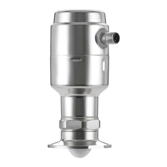
Non-contacting radar level transmitter
Hide thumbs
Also See for Rosemount 1408H:
- Reference manual (90 pages) ,
- Quick start manual (28 pages) ,
- Quick start manual (16 pages)

Related Manuals for Emerson Rosemount 1408H


Summary of Contents for Emerson Rosemount 1408H
- Page 1 Reference Manual 00809-0100-4480, Rev AA September 2020 ™ Rosemount 1408H Level Transmitter Non-Contacting Radar...
- Page 2 Equipment service needs. • 1-800-654-7768 (24 hours a day — includes Canada) • Outside of these areas, contact your local Emerson representative. WARNING Failure to follow safe installation and servicing guidelines could result in death or serious injury. • Ensure the transmitter is installed by qualified personnel and in accordance with applicable code of practice.
-
Page 3: Table Of Contents
Reference Manual Contents 00809-0100-4480 September 2020 Contents Chapter 1 Introduction......................5 1.1 Using this manual........................5 1.2 Product recycling/disposal......................5 Chapter 2 Transmitter overview....................7 2.1 Measurement principle........................ 7 2.2 Process characteristics......................... 7 2.3 Vessel characteristics........................8 2.4 Application examples........................8 2.5 Components of the transmitter....................10 2.6 Easy integration with IO-Link..................... - Page 4 B.6 Radio Equipment Directive (RED) 2014/53/EU................83 B.7 Additional certifications......................84 Appendix C Configuration parameters..................85 C.1 Menu tree..........................85 C.2 Basic setup..........................86 C.3 Digital output..........................88 C.4 Analog output........................... 91 C.5 Geometry..........................92 C.6 Advanced setup.........................94 Rosemount 1408H Level Transmitter...
-
Page 5: Chapter 1 Introduction
Reference Manual Introduction 00809-0100-4480 September 2020 Introduction Using this manual The sections in this manual provide information on installing, operating, and maintaining ™ the Rosemount 1408H Level Transmitter – Non-Contacting Radar. The sections are organized as follows: Transmitter overview provides an introduction to theory of operation, a description of the transmitter, information on typical applications, and process characteristics. - Page 6 Introduction Reference Manual September 2020 00809-0100-4480 Rosemount 1408H Level Transmitter...
-
Page 7: Chapter 2 Transmitter Overview
September 2020 Transmitter overview Measurement principle The Rosemount 1408H is a transmitter for continuous level measurements in the hygienic industry. The measurement principle is fast-sweep Frequency Modulated Continuous Wave (FMCW). The transmitter continuously emits signal sweeps with a constantly varying frequency towards the product surface. -
Page 8: Vessel Characteristics
The Rosemount 1408H uses Frequency Modulated Continuous Wave (FMCW) technology and smart algorithms to maximize measurement accuracy and reliability, even in small tanks and challenging fast-filling vessels. - Page 9 Reference Manual Transmitter overview 00809-0100-4480 September 2020 Mixing tanks Ensure correct filling and storage levels in tanks with agitators. Batch filling Optimize the batch filling process. CIP process Reliable level measurement during and after cleaning, plus optimization of cleaning agent storage.
-
Page 10: Components Of The Transmitter
E. ISO 228/1-G1 thread F. Antenna (PTFE sealing) G. Hygienic adapter O-ring H. Hygienic process connection adapter Figure 2-3: O-ring and Profile Ring A. DIN 3869 profile ring B. Hygienic adapter O-ring Related information Dimensional drawings Rosemount 1408H Level Transmitter... -
Page 11: Easy Integration With Io-Link
00809-0100-4480 September 2020 Easy integration with IO-Link The Rosemount 1408H provides both conventional 4-20 mA and digital switch outputs, enabled by IO-Link connectivity. This supports easy integration into any automation system. Each IO-Link system consists of an IO-Link master and one or more IO-Link devices (sensors and actuators). - Page 12 Transmitter overview Reference Manual September 2020 00809-0100-4480 Rosemount 1408H Level Transmitter...
-
Page 13: Chapter 3 Mechanical Installation
Reference Manual Mechanical installation 00809-0100-4480 September 2020 Mechanical installation Safety messages Instructions and procedures in this section may require special precautions to ensure the safety of the personnel performing the operations. Information that potentially raises safety issues is indicated by a warning symbol ( ). - Page 14 Do not mount close to or above the inlet stream. • Do not position the transmitter directly over a side manway door. • Multiple Rosemount 1408H transmitters can be used in the same tank without interfering with each other. Figure 3-1: Recommended Mounting Position 3.2.2...
- Page 15 Reference Manual Mechanical installation 00809-0100-4480 September 2020 3.2.3 Inclination The transmitter should be mounted vertically to ensure a good echo from the product surface. See Figure 3-3 for recommended maximum inclination. Figure 3-3: Inclination Max. 3° 90° 3.2.4 Non-metallic tanks Nearby objects outside the tank may cause disturbing radar echoes.
- Page 16 1.2 ft. (0.4 m) 13.1 ft. (4 m) 2.3 ft. (0.7 m) 19.7 ft. (6 m) 3.5 ft. (1.1 m) 26.2 ft. (8 m) 4.6 ft. (1.4 m) 32.8 ft. (10 m) 5.8 ft. (1.8 m) Rosemount 1408H Level Transmitter...
- Page 17 Reference Manual Mechanical installation 00809-0100-4480 September 2020 3.2.6 Nozzle requirements To allow the microwaves to propagate undisturbed, the nozzle dimensions should be kept within the specified limits as given in Table 3-3. The inside of the nozzle must be smooth (i.e.
- Page 18 Related information Dimensional drawings 3.2.8 Instructions for hygienic installations To conform with applicable hygienic standards and food and beverage legislation and regulations, the Rosemount 1408H must be: • Installed in a closed tank. • Installed with hygienic adapter and O-ring.
- Page 19 Reference Manual Mechanical installation 00809-0100-4480 September 2020 Clean-In-Place (CIP) Withstands cleaning routines up to 194 °F (90 °C) Steam-In-Place (SIP) Withstands cleaning routines up to 284 °F (140 °C) 3.2.9 Hygienic adapter O-ring The adapter comes with an EPDM O-ring. More O-rings are available as accessories. Related information Product Data Sheet Reference Manual...
-
Page 20: Mounting Preparations
Remove the protective cap The protective cap protects the PTFE sealing from impacts during transport and storage. Procedure Before installing, carefully remove the protective cap. Note Be careful not to scratch or otherwise damage the PTFE sealing. Rosemount 1408H Level Transmitter... - Page 21 Reference Manual Mechanical installation 00809-0100-4480 September 2020 ® 3.3.2 Tri Clamp, dairy coupling, and VARIVENT Install the adapter Procedure 1. Place the O-ring in the groove of the transmitter. Note Be careful not to scratch or otherwise damage the PTFE sealing. 2.
- Page 22 5. Secure the transmitter and adapter using a vise. CAUTION Do not over-tighten the vise as it might damage the adapter. 6. Tighten the transmitter to the recommended torque. Note Further tightening may affect the sealing. Torque 310 in-lb (35 N-m) 39 mm Rosemount 1408H Level Transmitter...
- Page 23 Reference Manual Mechanical installation 00809-0100-4480 September 2020 3.3.3 Weld-in adapter Mount the welding mandrel The welding mandrel absorbs heat and can prevent warping during installation of the weld-in adapter. Prerequisites CAUTION While welding, the weld-in adapter and mandrel can get extremely hot. To prevent burns, allow the components to cool before disassembling the weld-in adapter and mandrel assembly.
- Page 24 Procedure 1. Weld the adapter. Note While welding, prevent the adapter from warping. a) Fix the adapter in several spots with a sufficient adhesive force. Apply the fixing points at equal distances opposite each other. Rosemount 1408H Level Transmitter...
- Page 25 Reference Manual Mechanical installation 00809-0100-4480 September 2020 b) Apply the welding seams between the fixing points opposite each other. Ensure sufficient and even distance between the individual sections to avoid glowing through or warping of the adapter caused by overheating. 2.
-
Page 26: Mount Transmitter On Tank
1. Place a suitable gasket on top of the tank flange. 2. Lower the transmitter into the nozzle. Note Be careful not to scratch or otherwise damage the PTFE sealing. 3. Tighten the clamp to the recommended torque (see the manufacturer’s instruction manual). Rosemount 1408H Level Transmitter... - Page 27 Reference Manual Mechanical installation 00809-0100-4480 September 2020 3.4.2 Mount the dairy coupling (DIN 11851) Procedure 1. Place a suitable gasket on top of the tank flange. 2. Lower the transmitter into the nozzle. Note Be careful not to scratch or otherwise damage the PTFE sealing. 3.
- Page 28 1. Mount a suitable O-ring on the adapter. 2. Lower the transmitter into the nozzle. Note Be careful not to scratch or otherwise damage the PTFE sealing. 3. Tighten the clamp to the recommended torque (see the manufacturer’s instruction manual). Rosemount 1408H Level Transmitter...
- Page 29 Reference Manual Mechanical installation 00809-0100-4480 September 2020 3.4.4 Mount on a threaded connection Procedure 1. Grease the transmitter thread with lubricating paste. Note The paste must be approved for the application and compatible with the elastomers used. 2. Mount the transmitter on the tank. Torque 310 in-lb (35 N-m) 39 mm Note...
- Page 30 3. Tighten the transmitter to the recommended torque. Torque 310 in-lb (35 N-m) 39 mm Note Over tightening the transmitter can impair the seal. If the sealing areas are damaged, replace the O-ring or the entire process connector. Rosemount 1408H Level Transmitter...
-
Page 31: Chapter 4 Electrical Installation
Reference Manual Electrical installation 00809-0100-4480 September 2020 Electrical installation Safety messages Instructions and procedures in this section may require special precautions to ensure the safety of the personnel performing the operations. Information that potentially raises safety issues is indicated by a warning symbol ( ). - Page 32 Table 4-1: Pin Assignment Wire color Signal Brown 24 V power supply White OUT2 Digital output or active 4-20 mA analog output Blue Ground line Black OUT1/IO-Link Digital output or IO-Link mode According to IEC 60947-5-2. Rosemount 1408H Level Transmitter...
- Page 33 Reference Manual Electrical installation 00809-0100-4480 September 2020 Figure 4-2: Example Circuits 2: OUT2 4: OUT1 2: OUT2 4: OUT1 2: OUT2 4: OUT1 2: OUT2 4: OUT1 A. 2 x Digital output PnP B. 2 x Digital output NpN C. 1 x Digital output PnP / 1 x Analog output D.
-
Page 34: Power Up Transmitter
Power up transmitter Prerequisites Procedure Verify the power supply is disconnected. 2. Insert the M12 connector and screw tight. See the manufacturer’s instruction manual for recommended torque. 3. Connect the power supply. Related information Ingress protection Rosemount 1408H Level Transmitter... -
Page 35: Chapter 5 Configuration
Reference Manual Configuration 00809-0100-4480 September 2020 Configuration Safety messages Instructions and procedures in this section may require special precautions to ensure the safety of the personnel performing the operations. Information that potentially raises safety issues is indicated by a warning symbol ( ). -
Page 36: Get Started With Your Preferred Configuration Tool
The Device description files (IODD): download and install window opens. 2. In the Vendor list, select Rosemount Inc., and then select the check box for the devices to be installed/updated. Alternatively, select Browsing and navigate to an already downloaded IODD file. 3. Select OK. Rosemount 1408H Level Transmitter... - Page 37 Reference Manual Configuration 00809-0100-4480 September 2020 ® 5.3.3 /DTM framework Download the IODD file Procedure Download the IODD from the IODDFinder portal at Ioddfinder.io-link.com. ® Integrate IODDs into an FDT /DTM framework An IODD DTM Interpreter is required to integrate IODDs into an FDT/DTM environment (e.g PACTware).
-
Page 38: Connect The Transmitter To The Io-Link
Procedure 1. Under Menu, select Parameter → Basic Setup. 2. In the Engineering Units list, select Metric or Imperial. Option Description Metric Length: m Temperature: °C Imperial Length: in. Temperature: °F 3. Select Write to device. Rosemount 1408H Level Transmitter... - Page 39 Reference Manual Configuration 00809-0100-4480 September 2020 5.5.2 Enter the reference height Procedure 1. Under Menu, select Parameter → Basic Setup. 2. Enter the Reference Height. 3. Select Write to device. Related information Reference height 5.5.3 Configure the analog output The transmitter can be set to output the level as a 4-20 mA signal. Procedure 1.
- Page 40 Configuration Reference Manual September 2020 00809-0100-4480 Rosemount 1408H Level Transmitter...
-
Page 41: Operation And Maintenance
Reference Manual Operation and maintenance 00809-0100-4480 September 2020 Operation and maintenance Safety messages Instructions and procedures in this section may require special precautions to ensure the safety of the personnel performing the operations. Information that potentially raises safety issues is indicated by a warning symbol ( ). - Page 42 A value that triggers an alert, such as a high or low temperature indication, will change the overall status of the device, but the measurement might still be indicated as “Good” if the reliability of the data is good. Rosemount 1408H Level Transmitter...
-
Page 43: Enter The Demonstration Mode
Select Exit Demonstration Mode to return to normal operation (default mode). Replacing the O-ring The process wetted O-ring should be checked periodically. Replace with O-ring designed for Rosemount 1408H if there are any signs of damage. Procedure 1. Secure the transmitter and adapter using a vise. - Page 44 2. Unscrew the adapter from the transmitter. 39 mm 3. Remove the O-ring using a suitable non-metallic tool. Note Be careful not to scratch any of the surfaces. 4. If needed, clean the sealing areas. Related information Install the adapter Rosemount 1408H Level Transmitter...
-
Page 45: Service And Troubleshooting
Reference Manual Service and troubleshooting 00809-0100-4480 September 2020 Service and troubleshooting Safety messages Instructions and procedures in this section may require special precautions to ensure the safety of the personnel performing the operations. Information that potentially raises safety issues is indicated by a warning symbol ( ). -
Page 46: Diagnostic Messages
Device software fault – Check firmware revision Alarm classification Device status Failure Class Error Cause The software has detected an internal error. Recommended actions 1. Restart the device. 2. Restore default settings and reconfigure the device. Rosemount 1408H Level Transmitter... - Page 47 Reference Manual Service and troubleshooting 00809-0100-4480 September 2020 3. If the condition persists, replace the device. Related information Perform a device reset Restore to factory settings 7.2.4 Parameter error – Check data sheet and values Alarm classification Device status Functional Check Class Error Possible cause...
- Page 48 4. Restore default settings, restart device, and reconfigure the device. 5. If the condition persists, replace the device. Related information Analyze the echo peaks Adjust the general threshold Measurement recovery time Restore to factory settings Rosemount 1408H Level Transmitter...
- Page 49 Reference Manual Service and troubleshooting 00809-0100-4480 September 2020 Perform a device reset 7.2.8 Simulation active – Check operational mode Alarm classification Device status Functional Check Class Warning Possible cause The device is in simulation mode and is not reporting actual information. Recommended actions 1.
- Page 50 Verify voltage is 18-30 Vdc at the transmitter terminal. 7.2.13 Maintenance required - Cleaning Alarm classification Device status Maintenance required - Cleaning Class Notification Possible cause Product build-up on the antenna. Recommended actions Clean the antenna. Rosemount 1408H Level Transmitter...
- Page 51 Reference Manual Service and troubleshooting 00809-0100-4480 September 2020 Use a damp cloth and a mild cleaning agent suitable for the media and wetted parts of the transmitter. Note Take care not to scratch the PTFE sealing surfaces. Related information Material exposed to tank atmosphere Components of the transmitter Reference Manual...
-
Page 52: Troubleshooting Incorrect Level Readings
Verify the tank geometry parameters are configured correctly (especially the Reference Height). • Analyze the Echo Peaks and check General Threshold. • Restore default settings and reconfigure the device. Related information Reference height Analyze the echo peaks Adjust the general threshold Restore to factory settings Rosemount 1408H Level Transmitter... - Page 53 Reference Manual Service and troubleshooting 00809-0100-4480 September 2020 7.3.2 Level is stuck in measuring range Figure 7-2: Symptom A. Level B. Time C. Actual level D. Reported level Possible cause Disturbing object in the tank. Recommended actions • Analyze the Echo Peaks and check General Threshold. •...
- Page 54 Move the transmitter to another position. Possible cause Product build-up on the antenna. Recommended actions • Clean the antenna. Related information Analyze the echo peaks Adjust the general threshold Change the upper null zone Mounting position Rosemount 1408H Level Transmitter...
- Page 55 Reference Manual Service and troubleshooting 00809-0100-4480 September 2020 7.3.4 Level value drops when close to antenna Level value drops to a lower value when product surface is close to antenna. Figure 7-4: Symptom A. Level B. Time C. Actual level D.
- Page 56 Measured level fluctuates Figure 7-5: Symptom A. Level B. Time C. Reported level Possible cause Excessive foaming or turbulence. Recommended actions • Under turbulent conditions with low level rates, consider increasing the Damping value. Related information Damping value Rosemount 1408H Level Transmitter...
- Page 57 Reference Manual Service and troubleshooting 00809-0100-4480 September 2020 7.3.6 Measured level is occasionally unstable Figure 7-6: Symptom A. Level B. Time C. Actual level D. Reported level Possible cause The product surface is close to a suppressed false echo. Recommended actions •...
- Page 58 C. Actual level D. Reported level Possible cause Damping value is set too high. Recommended actions • If there is a problem with lag during rapid level changes, consider decreasing the Damping value. Related information Damping value Rosemount 1408H Level Transmitter...
- Page 59 Reference Manual Service and troubleshooting 00809-0100-4480 September 2020 7.3.8 Incorrect level at 100% (20 mA) Symptom Measured level is correct at 0% (4 mA) but incorrect at 100% (20 mA). Figure 7-8: Symptom A. Level B. Time C. Actual level D.
- Page 60 A. Level B. Time C. Actual level D. Reported level Possible cause A strong double bounce echo is interpreted as the product surface. Recommended actions • Move the transmitter to another position. Related information Mounting position Rosemount 1408H Level Transmitter...
- Page 61 Reference Manual Service and troubleshooting 00809-0100-4480 September 2020 7.3.10 Dropping of level close to tank bottom Symptom Measured value drops to zero level in the tank bottom region. Figure 7-10: Symptom A. Level B. Time C. Actual level D. Reported level Possible cause Transmitter has locked on a strong tank bottom echo.
- Page 62 "Level measurement lost". The message is cleared when start filling the tank. Recommended actions • Before opening the manway door, disconnect power to the transmitter. • After closing, restart the device. • Move the transmitter to another position. Related information Mounting position Perform a device reset Rosemount 1408H Level Transmitter...
-
Page 63: Managing Disturbance Echoes
Reference Manual Service and troubleshooting 00809-0100-4480 September 2020 7.3.12 Alarm mode close to tank bottom Symptom When the product surface is near the sloped tank bottom, the transmitter enters alarm mode. Figure 7-12: Symptom A. Level B. Time C. Actual level D. - Page 64 View the echo peaks to find out if there are disturbing echoes close to tank top. 2. Set the desired Upper Null Zone value. a) Under Menu, select Parameter → Geometry → Advanced. b) Enter the desired Upper Null Zone value. c) Select Write to device. Rosemount 1408H Level Transmitter...
-
Page 65: Service And Troubleshooting Tools
Reference Manual Service and troubleshooting 00809-0100-4480 September 2020 Figure 7-13: Upper Null Zone A. Upper Null Zone B. Disturbance echo C. 100% (20 mA) D. General threshold E. Product surface echo Related information Upper null zone Service and troubleshooting tools 7.5.1 Analyze the echo peaks Measurement problems can be understood by studying the position and amplitude of the... - Page 66 4 mA and 20 mA currents. Calibration is done at factory and the analog output does not normally need to be recalibrated. Prerequisites Connect a calibrated ampere meter to the analog output loop. Rosemount 1408H Level Transmitter...
- Page 67 Reference Manual Service and troubleshooting 00809-0100-4480 September 2020 Procedure 1. Under Menu, select Parameter → Service Tools → Analog Out Calibration. 2. Perform the calibration of 4 mA. a) Select Enter 4 mA Fixed Current Mode to set the analog out to 4 mA. b) Measure the analog output with the ampere meter.
- Page 68 Select Write different values to device (Write to device in Rosemount IO- Link Assistant). 3. Verify the written value by reading the holding register number. 4. Perform a device reset to write protect the holding registers. Related information Perform a device reset Rosemount 1408H Level Transmitter...
-
Page 69: Service Support
00809-0100-4480 September 2020 Service support To expedite the return process outside of the United States, contact the nearest Emerson representative. Within the United States, call the Emerson Instrument and Valve Response Center using the 1-800-654-RSMT (7768) toll-free number. This center, available 24 hours a day, will assist you with any needed information or materials. - Page 70 Service and troubleshooting Reference Manual September 2020 00809-0100-4480 Rosemount 1408H Level Transmitter...
-
Page 71: Appendix A Specifications And Reference Data
Reference Manual Specifications and reference data 00809-0100-4480 September 2020 Specifications and reference data Performance specifications A.1.1 General Reference conditions • Measurement target: Stationary metal plate, no disturbing objects • Temperature: 59 to 77 °F (15 to 25 °C) • Ambient pressure: 14 to 15 psi (960 to1060 mbar) •... - Page 72 Pressure Equipment Directive (PED) Complies with 2014/68/EU article 4.3 Radio approvals • Radio Equipment Directive (2014/53/EU): ETSI EN 302 372 (TLPR) and EN 62479 • Part 15 of the FCC Rules • Industry Canada RSS 211 Rosemount 1408H Level Transmitter...
-
Page 73: Functional Specifications
Reference Manual Specifications and reference data 00809-0100-4480 September 2020 Functional specifications A.2.1 General Field of application Continuous level measurements in the hygienic industry. Minimum dielectric constant Measurement principle Frequency Modulated Continuous Wave (FMCW) Frequency range 77 to 81 GHz Maximum output power 3 dBm (2 mW) Internal power consumption <... - Page 74 Maximum loop resistance is determined by the voltage level of the external power supply: Maximum Loop Resistance = 43.5 × (External Power Supply Voltage - 18) + 600 Ω Figure A-2: Load Limits 1200 1121 1100 1000 A. Loop Resistance (Ω) B. External Power Supply Voltage (Vdc) Rosemount 1408H Level Transmitter...
- Page 75 Reference Manual Specifications and reference data 00809-0100-4480 September 2020 Analog signal on alarm The transmitter automatically and continuously performs self-diagnostic routines. If a failure or a measurement error is detected, the analog signal will be driven offscale to alert the user. High or low failure mode is user-configurable. Table A-1: Signal on Alarm Level Custom levels...
- Page 76 -15 to 116 psig (-1 to 8 bar) Atmospheric pressure at temperatures below -4 °F (-20 °C) A.2.8 Temperature limits Process temperature With adapter -4 to 302 °F (-20 to 150 °C) Without adapter -40 to 302 °F (-40 to 150 °C) Rosemount 1408H Level Transmitter...
-
Page 77: Physical Specifications
Emerson is not in a position to evaluate or guarantee the compatibility of the process fluid or other process parameters with the product, options, configuration or materials of construction selected. - Page 78 Material exposed to tank atmosphere With adapter • PTFE sealing: PTFE fluoropolymer • Adapter: 316L (EN 1.4435) • Hygienic O-ring: EPDM or FKM Adapter not included. IP68 at 9.8 ft. (3 m) for more than 30 minutes. Rosemount 1408H Level Transmitter...
- Page 79 Reference Manual Specifications and reference data 00809-0100-4480 September 2020 Without adapter • PTFE sealing: PTFE fluoropolymer • O-ring: FVMQ • G1 thread: 316L (EN 1.4404) • Profile ring: FKM Reference Manual...
-
Page 80: Dimensional Drawings
Specifications and reference data Reference Manual September 2020 00809-0100-4480 Dimensional drawings Figure A-4: Rosemount 1408H Ø 2.32 (59) 2.99 (76) 5.79 4.76 (147) (121) 0.39 (10) A. ISO 228/1-G1 thread B. M12 connector (A-coded) C. Hygienic process connection adapter Dimensions are in inches (millimeters). -
Page 81: Appendix B Product Certifications
TLPR (Tank Level Probing Radar) equipment are devices for measurement of level in a closed space only (i.e metallic or reinforced concrete or fiberglass tanks, or similar enclosure structures made of comparable attenuating material). Rosemount 1408H is TLPR device. Hardware Version Identification Number (HVIN) is 1408T. -
Page 82: Fcc
Director of the DRAO before the equipment can be installed or operated. The Director of the DRAO may be contacted at 250-497-2300 (tel.) or 250-497-2355 (fax). (Alternatively, the Manager, Regulatory Standards, Industry Canada, may be contacted.) Rosemount 1408H Level Transmitter... -
Page 83: Radio Equipment Directive (Red) 2014/53/Eu
2827A-1408T Radio Equipment Directive (RED) 2014/53/EU Rosemount 1408H complies with ETSI EN 302 372 (TLPR) and EN 62479. For the receiver test that covers the influence of an interferer signal to the device, the performance criterion has at least the following level of performance according to ETSI TS 103 361 [6]. -
Page 84: Additional Certifications
Table B-2: Nonproduct Contact Surfaces Item Material Housing Stainless steel 300 series Bushing Stainless steel 300 series Plug Stainless steel 300 series Adapter seal Electrical connector Contact pins in gold plated brass Housing in plastics (PA) Seal in FKM Rosemount 1408H Level Transmitter... -
Page 85: Appendix C Configuration Parameters
Reference Manual Configuration parameters 00809-0100-4480 September 2020 Configuration parameters Menu tree Figure C-1: Parameter Menu > Parameter Basic Setup Engineering Units Reference Height OUT1 Configuration OUT2 Configuration Digital Outputs P-n Write Protection OUT1 Digital Output 1 High Alarm SP1-High Alarm Set Point SP2-Low Alarm Set Point Low Alarm DO1 Advanced... -
Page 86: Basic Setup
Ensure the Reference Height is set as accurate as possible. The transmitter measures the distance to the product surface and subtracts this value from the Reference Height to determine the level. Related information Enter the reference height Rosemount 1408H Level Transmitter... - Page 87 Reference Manual Configuration parameters 00809-0100-4480 September 2020 Device reference point The Device Reference Point is located at the underside of the adapter as illustrated in Figure C-3. Figure C-3: Device Reference Point C.2.3 OUT1 configuration Output 1 provides a digital output for high/low level limits and IO-Link communication. Table C-1: Options for OUT1 Option Description...
-
Page 88: Digital Output
D. SP1 - Hysteresis high alarm Low alarm Enable or disable the low level alarm (dry run alarm). Figure C-5: Example - Low Alarm A. Level B. Time C. SP2 - Hysteresis low alarm D. SP2 - Low alarm set point Rosemount 1408H Level Transmitter... - Page 89 Reference Manual Configuration parameters 00809-0100-4480 September 2020 Alarm set points SP1 - High alarm set point If the measured level is above this set point, the digital output is set to alarm state. SP2 - Low alarm set point If the measured level is below this set point, the digital output is set to alarm state. Hysteresis The hysteresis is a buffer zone so the alerts do not toggle on and off when the measurement value fluctuates around the alarm limit.
- Page 90 Figure C-7: Behavior of the Alarm On Delay Always Lost surface A. Level B. Time C. SP1 - High alarm set point D. Alarm on delay E. Lost surface (invalid level) Rosemount 1408H Level Transmitter...
-
Page 91: Analog Output
Reference Manual Configuration parameters 00809-0100-4480 September 2020 Analog output C.4.1 Upper/lower range value Enter the range values that correspond to the analog output values 4 and 20 mA. In normal operation, the transmitter will drive the output in response to level from the lower to upper saturation points. -
Page 92: Geometry
A positive Calibration Offset value will increase the presented level value. Figure C-9: Calibration Offset A. Positive Calibration Offset value B. Negative Calibration Offset value C. Reported level D. Actual level Rosemount 1408H Level Transmitter... - Page 93 Reference Manual Configuration parameters 00809-0100-4480 September 2020 Upper null zone The Upper Null Zone defines how close to the transmitter's reference point a level value is accepted. You can extend this value to block out disturbing echoes close to the antenna, for example from the tank nozzle.
-
Page 94: Advanced Setup
The general threshold is used to filter out noise and disturbing echoes from the product surface echo. The transmitter uses certain criteria to decide which type of echo peak that is detected. Only echoes above the general threshold might be considered the product surface. Rosemount 1408H Level Transmitter... - Page 95 Reference Manual Configuration parameters 00809-0100-4480 September 2020 Figure C-11: Threshold Principle A. General threshold B. Product surface echo Related information Adjust the general threshold Reference Manual...
- Page 96 Configuration parameters Reference Manual September 2020 00809-0100-4480 Rosemount 1408H Level Transmitter...
- Page 97 Reference Manual 00809-0100-4480 September 2020 Reference Manual...
- Page 98 Emerson Terms and Conditions of Sale are available upon request. The Emerson logo is a Facebook.com/Rosemount trademark and service mark of Emerson Electric Co. Rosemount is a mark of one of the Youtube.com/user/RosemountMeasurement Emerson family of companies. All other marks are the property of their respective owners.
Need help?
Do you have a question about the Rosemount 1408H and is the answer not in the manual?
Questions and answers