Table of Contents
Advertisement
Quick Links
Advertisement
Table of Contents

Related Manuals for Cornelius Impulse XL


Summary of Contents for Cornelius Impulse XL
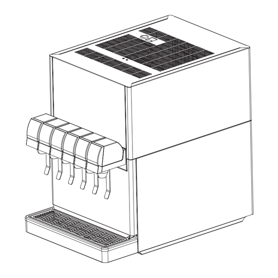
- Page 1 Impulse XL Post-mix Beverage Dispenser Operator’s Manual 890519401...
-
Page 3: Table Of Contents
Electronic Control Board Function ..............16 Ice Bank Control ...................16 Carbonator Control ..................17 LED Diagnostics ...................17 OPERATIONS ......................19 Operations ......................19 Starting And Stopping The Unit ................19 Dispensing Product ...................19 Replenishing Syrup Supply ................19 Adjustments ......................20 Water-to-syrup Ratio Adjustment ..............20 © 2010, IMI Cornelius Inc. - Page 4 Pump Motor Replacement .................35 Agitator Motor Replacement Controller Board Replacement ................36 ..............37 Condenser Fan Motor Replacement ..................38 Power Cord Replacement ................39 Illustrated Parts List (Intellicarb) ......................44 Reference Material ....................44 Wiring Diagram ..............45 Plumbing Diagram - Internal Carbonator © 2010, IMI Cornelius Inc.
-
Page 7: General Information
The 2/3 H.P. refrigeration deck is easily removed for service and maintenance. Adjustable water "ow regulators and syrup "ow regulators, located on dispensing valves, are easily accessible. ON/OFF Key Lock Switches Switch Removable Refrigeration Deck Removable Drip Tray © 2010, IMI Cornelius Inc. - 3 -... -
Page 8: Speci!Cations
– a 90°F (32 °C) ambient temperature – two 12-oz. (340g) drinks per minute – drinks dispensed at 40° F (5 °C) or below Capacities by unit are: Raja unit, 230 volt, 50 Hz, 250 drinks continuously © 2010, IMI Cornelius Inc. - 4 -... -
Page 9: Theory Of Operation
A still (non-carbonated) drink is dispensed in the same manner as the carbon- ated drink except plain water is substituted for carbonated water. - 5 - © 2010, IMI Cornelius Inc. - Page 10 NOTE © 2010, IMI Cornelius Inc. - 6 -...
-
Page 11: Installation
Remove shipping tape and other packing material. Unpack the loose parts and make sure all items are present. LOOSE PARTS Name Quantity Cup rest Drip tray Drain hose Hose clamp Service Manual © 2010, IMI Cornelius Inc. - 7 -... -
Page 12: Electrical Requirements
CAUTION of clearance on all sides and 18 - inch (0.45 m) on the top of the unit. — This unit is designed for indoor installation only (in non harsh environments). CAUTION - 8 - © 2010, IMI Cornelius Inc. -
Page 13: Installation Procedure
2. Remove two mounted screws from the top and Lift Top-cover off. Remove Two Screws Before Remove Top-cover CAUTION — Make sure that the power to the unit is disconnected (unplugged) before removing the covers. © 2010, IMI Cornelius Inc. - 9 -... - Page 14 The ice bank control ice. Once this happens, the ice bank control module senses this by measuring the differ- module starts the refrigeration compressor ence in electrical resistance between the and the condenser fan motor. - 10 - © 2010, IMI Cornelius Inc.
- Page 15 Check to see that the agitator motor has started. After about three minutes the compressor should start. If the agitator or compressor do not start call Technical Services. Power Switch © 2010, IMI Cornelius Inc. - 11 -...
-
Page 16: Connect Syrup, Water, And Carbonated Water Lines
50 psi, a water pressure regulator must be installed in the supply line. NOTE A water shutof f valve and water !lter in the water supply line are recommended. - 12 - © 2010, IMI Cornelius Inc. - Page 17 Bleed the air out of the carbonator (hold with wrench) Bleed Valve by pulling up on the metal ring on the bleed valve. Bleed each valve into a bucket until water comes out for 2-3 seconds. © 2010, IMI Cornelius Inc. - 13 -...
-
Page 18: Check For Leaks
4. Check the system for water and syrup leaks. Reinstall Panels 1. Reinstall top and front vented panels as well as the front stainless steel panel. - 14 - © 2010, IMI Cornelius Inc. -
Page 19: Adjust Water-To-Syrup Ratio
!ow rate is 2.5 oz./sec. (70 g / sec.) and the syrup !ow rate is 0.5 oz./sec. (14 g / sec.) (The water at 2.5 oz./sec. (70 g / sec.) is "ve times the 0.5 oz./sec. (14 g / sec.) syrup !ow rate.) - 15 - © 2010, IMI Cornelius Inc. -
Page 20: Electronic Control Board Function
The control board will not restart the compressor until after the compressor has been off for at least 3 minutes to allow the refrigeration system pressures to equalize. © 2010, IMI Cornelius Inc. - 16 -... -
Page 21: Carbonator Control
3-minute continuous run period has been exceeded (red LED ON). To reset the control board toggle the main power switch OFF, wait 15 seconds, then toggle to ON. - 17 - © 2010, IMI Cornelius Inc. - Page 22 NOTE © 2010, IMI Cornelius Inc. - 18 -...
-
Page 23: Operations
1. Disconnect the syrup tube from the empty bag-in-box and remove the empty box. 2. Rinse the disconnects in warm water to remove any syrup residue. 3. Install a full bag-in-box and connect the syrup tube. - 19 - © 2010, IMI Cornelius Inc. -
Page 24: Adjustments
DJUSTMENTS Water-to-Syrup R atio Adjustment The ratio adjustment should only be done by a quali!ed service person. © 2010, IMI Cornelius Inc. - 20 -... - Page 25 © 2010, IMI Cornelius Inc. - 21 -...
- Page 26 © 2010, IMI Cornelius Inc. - 22 -...
-
Page 27: Double Liquid Check Valve Inspection & Cleaning
Failure to comply could result in serious injury,death or damage to the equipment. 3. V use low pressure compressed air. 4. Clean around top of refrigeration assembly. 5. Reinstall merchandiser - 22a - © 2010, IMI Cornelius Inc. -
Page 28: Service
Refer to Section (page 15) Should be done whenever "avors are changed or any service is preformed. LEAN ONDENSER OPERATION (page 22) Refer to Section LEAN ONNECTORS OPERATION (page 21) Refer to Section - 23 - © 2010, IMI Cornelius Inc. -
Page 29: Adjustments
NOTE -- The Colt dispenser with integral cold carbonator requires CO supply pressure of 75 psi (5.2 bar). 3. Bleed air from the lines with the relief valves. 4. Check the system for gas leaks. - 24 - © 2010, IMI Cornelius Inc. -
Page 30: Trouble Shooting
4. Repair dispensing valve syrup !!!!valve!syrup! ow!control. !!!! ow!control. 5. Tapered washer inside 5. Replace tapered gasket. tube swivel nut connec- Make sure it seatsproperly. tion distorted from being over tightened restricting !!!!syrup! o - 25 - © 2010, IMI Cornelius Inc. - Page 31 Allow ice to become “wet” before using. (refer to following NOTE). NOTE : Crushed ice also causes dispensing problems. When "nished drink hits sharp edges of ice, carbonation is released from dispensed drink. - 26 - © 2010, IMI Cornelius Inc.
- Page 32 5. Tapered gasket inside 5. Replace tapered gasket. carbonated water line swivel nut Make sure it is properly connector distorted restricting seated. carbonated water !o 6. Dirty water supply. 6. Check water "lte Replace cartridge. - 27 - © 2010, IMI Cornelius Inc.
- Page 33 3. water, oil or dirt in CO 3. Have service person supply. remove contaminated supply, then clean system (lines, regulator, etc.) using a mild detergent. install a clean CO supply. - 28 - © 2010, IMI Cornelius Inc.
- Page 34 4. Inoperative carbonated water 4. Replace probe (see note). tank water level probe. 5. Inoperative carbonator pump 5. Replace pump or motor. or motor. 6. Inoperative control board. 6. Replace control board. - 29 - © 2010, IMI Cornelius Inc.
- Page 35 Motor Not Operating “ in this section. 10. Inoperative overload protector 10. Replace inoperative part. or start relay. 11. Inoperative ice bank probe. 11. Replace ice bank probe. 12. Inoperative control board. 12. Replace control board. - 30 - © 2010, IMI Cornelius Inc.
- Page 36 4. Loose, disconnected, or broken 4. Tighten connections or wiring. replace broken wiring. 5. Inoperative agitator moto 5. Replace agitator moto - 31 - © 2010, IMI Cornelius Inc.
- Page 37 NOTE © 2010, IMI Cornelius Inc. - 32 -...
-
Page 38: Component Service
4. Depressurize carbonator by removing the solenoid dust cover from any dispensing Press Valve valve and push down Solenoid to on the solenoid. Depressurize Pump Water 5. Disconnect water in and out lines. Connections © 2010, IMI Cornelius Inc. - 33 -... -
Page 39: Pump Motor Replacement
• key switch wires • hood by removing screws on the top and lifting up and forward. 3. Unplug motor harness. 4. Loosen the V - band clamp and remove pump. Pump V - Band - 34 - © 2010, IMI Cornelius Inc. -
Page 40: Agitator Motor Replacement
• hood by removing screws on the top and lifting up and forward. 3. Unplug motor harness. 4. Remove mounting screw. Mounting Screw 5. Slide motor out of retainer slots and lift up. - 35 - © 2010, IMI Cornelius Inc. -
Page 41: Controller Board Replacement
3. Push the cover off as arrow direction. 4. Unplug all connectors. 5. Squeeze all four standoffs remove the board. Connector in each Corner 6. Install new controller board by reversing this procedure. © 2010, IMI Cornelius Inc. - 36 -... -
Page 42: Condenser Fan Motor Replacement
4. Lift mounting bracket front tab out of slot, then pull motor out from the back. 5. Remove three screws holding motor to bracket and remove motor. 3 Screws 6. Install new motor by reversing this procedure. - 37 - © 2010, IMI Cornelius Inc. -
Page 43: Power Cord Replacement
Use the already attached wire tie/fastener on the deck to secure the cord. Cord Fastener 4 C. Connect cord to the receptacle on the refrigeration deck. Plug Cord into Receptacle © 2010, IMI Cornelius Inc. - 38 -... - Page 44 - 39 - © 2010, IMI Cornelius Inc.
-
Page 45: Illustrated Parts List (Intellicarb)
ILLUSTRATED PARTS LIST " FIGURE 2. HOOD AND PANEL COMPONENTS " ! & '& " " " * ( '' - 40 - © 2010, IMI Cornelius Inc. - Page 46 ILLUSTRATED PARTS LIST FIGURE 3. COIL AND CARBONATOR COMPONENTS © 2010, IMI Cornelius Inc. - 41 -...
- Page 47 ILLUSTRATED PARTS LIST FIGURE 4. PUMP AND MOTOR ASSEMBLY © 2010, IMI Cornelius Inc. - 42 -...
- Page 48 ILLUSTRATED PARTS LIST FIGURE 5. REFRIGERATION ASSEMBLY ( /%$& 1& / $ %& ! "# $ %& - 43 - © 2010, IMI Cornelius Inc.
-
Page 49: Reference Material
REFERENCE MATERIAL IRING IAGRAM © 2010, IMI Cornelius Inc. - 44 -... - Page 51 NOTE © 2010, IMI Cornelius Inc. - 46 -...
Need help?
Do you have a question about the Impulse XL and is the answer not in the manual?
Questions and answers