Table of Contents
Advertisement
Service/Maintenance
Manual
IMPORTANT:
TO THE INSTALLER.
It is the responsibility of the
Installer to ensure that the water
supply to the dispensing
equipment is provided with
protection against backflow by an
air gap as defined in ANSI/ASME
A112. 1.2-1979; or an approved
vacuum breaker or other such
method as proved effective by
test.
Water pipe connections and
fixtures directly connected to a
potable water supply shall be
sized, installed, and maintained
according to Federal, State, and
Local laws.
Part No. 312031004
January 26, 1996
Revised: March 3, 1998
Control Code C
THIS DOCUMENT CONTAINS IMPORTANT INFORMATION
This Manual must
IMI CORNELIUS INC; 1998
Ó
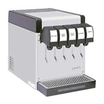
VANTAGE POST-MIX DISPENSER
PRINTED IN U.S.A
Advertisement
Table of Contents
Troubleshooting

Related Manuals for Cornelius Cornelius VANTAGE POST-MIX DISPENSER


Summary of Contents for Cornelius Cornelius VANTAGE POST-MIX DISPENSER
- Page 1 Federal, State, and Local laws. Part No. 312031004 January 26, 1996 Revised: March 3, 1998 Control Code C THIS DOCUMENT CONTAINS IMPORTANT INFORMATION This Manual must IMI CORNELIUS INC; 1998 Ó VANTAGE POST-MIX DISPENSER PRINTED IN U.S.A...
-
Page 2: Table Of Contents
SAFETY INFORMATION ........... . RECOGNIZE SAFETY INFORMATION UNDERSTAND SIGNAL WORDS FOLLOW SAFETY INSTRUCTIONS... - Page 3 TABLE OF CONTENTS (cont’ d) DISPENSED PRODUCT COMES OUT OF DISPENSING VALVE CLEAR BUT FOAMS IN CUP OR GLASS. DISPENSED PRODUCT PRODUCES FOAM AS IT LEAVES DISPENSING VALVE..........NO PRODUCT DISPENSED FROM ALL DISPENSING VALVES ONLY CARBONATED WATER DISPENSED.
-
Page 4: Safety Information
SAFETY INFORMATION Recognize Safety Information This is the safety-alert symbol. When you see this symbol on our machine or in this manual, be alert to the potentially of personal injury. Follow recommended precautions and safe operating practices. Understand Signal Words A signal word - DANGER, WARNING, OR CAUTION is used with the safety-alert symbol. - Page 6 THIS PAGE LEFT BLANK INTENTIONALLY 312031004...
-
Page 7: General Information
CLAIMS INSTRUCTIONS Claims: In the event of shortage, notify the carrier as well as IMI Cornelius immediately. In the event of dam- age, notify the carrier. IMI Cornelius is not responsible for damage occurring in transit, but will gladly render assistance necessary to pursue your claim. -
Page 8: Theory Of Operation
312031004... -
Page 9: Figure 3. Plumbing Diagram (Five-Flavor Unit W/Integral Carb And One Non-Carb Drink Shown)
312031004... -
Page 10: Figure 4. Plumbing Diagram
CARB WATER INLET CARB WATER COOLING COIL SYRUP INLET CARB WATER INLET CARB WATER COOLING COIL FIGURE 4. PLUMBING DIAGRAM (FOUR-FLAVOR UNIT REQUIRING REMOTE CARBONATOR) 312031004 SYRUP COOLING COIL (4) CARB WATER MANIFOLD DISPENSING VALVE (4) -
Page 11: Service And Maintenance
SERVICE AND MAINTENANCE This section describes the service and maintenance procedures to be performed on the Unit. IMPORTANT: Only qualified Service Personnel should service the internal components or electrical wiring. DANGER: To avoid possible fatal electrical shock or serious injury to the operator, it is required that a GFCI (ground fault circuit interrupt) be installed in the electrical circuit for the domestic Units. -
Page 12: Figure 6. Parts Identification
FRONT ACCESS PANEL FRONT ACCESS PANEL RETAINING SCREW (2) INSULATION PAD WATER TANK OVERFLOW TUBE CUP REST DRIP TRAY FIGURE 6. PARTS IDENTIFICATION (FIVE-FLAVOR UNIT WITH INTEGRAL CARBONATOR SHOWN) 312031004 HOOD RETAINING SCREW HOOD 115/24 VAC TRANSFORMER DROP-IN REFRIGERATION ASS’ Y DOUBLE LIQUID CHECK VALVE SYRUP INLET... -
Page 13: Figure 7. Parts Identification (Five-Flavor Unit Requiring Remote Carbonator Shown)
HOOD RETAINING SCREW HOOD CONDENSER FRONT ACCESS COIL PANEL AGITATOR MOTOR 115/24 VAC CONTROL TRANSFORMER DROP-IN REFRIGERATION ASS’ Y FRONT ACCESS PANEL RETAINING SCREW (2) WATER TANK OVERFLOW TUBE CUP REST DISPENSING VALVE (5) SYRUP INLET TUBE (5) CARB WATER INLET TUBE WATER TANK DRIP TRAY DRAIN HOSE... -
Page 14: Adjustments
2. Check the dispensing valves for dripping that indicates leakage and repair as necessary. ADJUSTMENTS REGULATORS ADJUSTMENTS WARNING: CO displaces oxygen. Strict attention must be observed in the prevention of (carbon dioxide) gas leaks in the entire CO suspected, particularly in a small area, immediately ventilate the contaminated area before attempting to repair the leak. -
Page 15: Adjusting Water-To-Syrup " Ratio"(Brix) Of Dispensed Product
Counterclockwise to Decrease Clockwise to Increase ADJUSTING WATER-TO-SYRUP “RATIO” (BRIX) OF DISPENSED PRODUCT (see Figure 8) NOTE: Make sure the dispensing valve water flow rate is as desired before adjusting the valve for Water-to-Syrup ‘ ‘ Ratio’ ’(Brix) of the dispensed product. Adjust Water--to--Syrup “... -
Page 16: Cleaning And Sanitizing
For less syrup, turn the adjusting screw counterclockwise no more than 1/4 turn at a time. For more syrup, turn the adjusting screw clockwise no more than 1/4 turn at a time. 6. Repeat water-to-syrup ratio test and adjust syrup flow regulator as many times as necessary until proper ratio of dispensed drink is achieved. - Page 17 Bag-in Box Syrup Systems. Install bag valves, cut from empty bag-in-box syrup containers, on ends of syrup containers syrup outlet tubes connectors. Place all syrup outlet tubes, with bag valves on their ends, in container containing detergent solution. 5. Flush the syrup system and dispensing valve as follows: Place waste container under applicable dispensing valve.
- Page 18 Activate the dispensing valve for one minute to purge all water from and install sanitizing solution in the syrup system and dispensing valve. Continue to activate the dispensing valve in cycle 312031004...
-
Page 19: Cleaning Drop-In Refrigeration Assembly Condenser Coil
25. Dispose of waste sanitizing solution in a sanitary sewer, not in a storm drain, then thoroughly rinse the inside and the outside of the container that was used for sanitizing solution to remove all sanitizing solution residue. CLEANING DROP-IN REFRIGERATION ASSEMBLY CONDENSER COIL (see applicable Figure 6 or 7) CAUTION: The refrigeration assembly condenser coil must be cleaned every 30-days. -
Page 20: Cleaning Water Tank
CLEANING WATER TANK (see Figure 6) 1. Unplug the Unit power cord from electrical outlet. 2. Close shutoff valve in plain water source line connected to the Unit. 3. Remove two screws securing the Unit front access panel, then remove the panel. 4. -
Page 21: Carbonator Water Pump Yearly Maintenance Or After Water System Disruptions
17. Dispense from one of the dispensing valves to make the carbonator cycle on and off. 18. Check for water leaks and repair if leaks are found. 19. Install Unit hood and secure with screw. 20. Install Unit front access panel and secure with two screws. CARBONATOR WATER PUMP YEARLY MAINTENANCE OR AFTER WATER SYSTEM DISRUPTIONS REMOTE CARBONATOR... -
Page 22: Figure 9. Wiring Diagram
FIGURE 9. WIRING DIAGRAM 312031004... -
Page 23: Troubleshooting
IMPORTANT: Only a qualified Service Person should service internal components or electrical wiring. DANGER: Disconnect electrical power to the Unit to prevent personal injury before attempting any electrical repairs to the internal components. If repairs are to be made to one of the syrup systems, disconnect syrup supply from the system, then bleed system pressure before proceeding. -
Page 24: Adjustment Of Dispensing Valve Syrup Regulator Does Not Decrease To Desired Water-To-Syrup ' ' Ratio
Trouble ADJUSTMENT OF DISPENSING VALVE SYRUP REGULATOR DOES NOT DECREASE TO DESIRED WATER-TO-SYRUP ‘ ‘ RATIO’ ’ . DISPENSED PRODUCT CARBONATION TOO LOW. DISPENSED PRODUCT COMES OUT OF DISPENSING VALVE CLEAR BUT FOAMS IN CUP OR GLASS. 312031004 Probable Cause Dirty or inoperative dispensing valve syrup flow control. -
Page 25: Dispensed Product Produces Foam As It Leaves
Trouble DISPENSED PRODUCT PRODUCES FOAM AS IT LEAVES DISPENSING VALVE. (cont’ d) NO PRODUCT DISPENSED FROM ALL DISPENSING VALVES ONLY CARBONATED WATER DISPENSED. ONLY SYRUP DISPENSED. TROUBLESHOOTING REFRIGERATION SYSTEM COMPRESSOR DOES NOT OPERATE. Probable Cause Dirty water supply. NOTE: If water supply is dirty, be sure to flush lines and carbonator carbonated water tank completely. -
Page 26: Compressor Will Not Stop After Sufficient Ice Bank Is Produced
Trouble COMPRESSOR DOES NOT OPERATE.(CONT’ D) COMPRESSOR WILL NOT STOP AFTER SUFFICIENT ICE BANK IS PRODUCED. COMPRESSOR OPERATES CONTINUOUSLY BUT DOES NOT FORM SUFFICIENT ICE BANK. CONDENSER FAN MOTOR NOT OPERATING. AGITATOR MOTOR NOT OPERATING. 312031004 Probable Cause Inoperative overload protector or start relay. -
Page 27: Warranty
IMI Cornelius Inc. warrants that all equipment and parts are free from defects in material and workmanship under normal use and service. For a copy of the warranty applicable to your Cornelius, Remcor or Wilshire product, in your country, please write, fax or telephone the IMI Cornelius office nearest you. Please provide the equipment model number, serial number and the date of purchase. - Page 29 IMI CORNELIUS INC. CORPORATE HEADQUARTERS: One Cornelius Place Anoka, Minnesota 55303-6234 (612) 421-6120 (800) 238-3600...
Need help?
Do you have a question about the Cornelius VANTAGE POST-MIX DISPENSER and is the answer not in the manual?
Questions and answers