
Related Manuals for ICP DAS USA MDC-714i


Summary of Contents for ICP DAS USA MDC-714i
- Page 1 MDC-700 Series User Manual Aug. 2021, Version 1.0.4 SUPPORT MDC-711 Written by Liam Lin Edited by Sunny Chiu MDC-714/MDC-714i MDC-741 MDC-771...
- Page 2 Warranty All products manufactured by ICP DAS are warranted against defective materials for a period of one year from the date of delivery to the original purchaser. Warning ICP DAS assumes no liability for damages consequent to the use of this product. ICP DAS reserves the right to change this manual at any time without notice.
-
Page 3: Table Of Contents
Contents 1. Introduction ............................4 2. Hardware Information ........................7 2.1. Specifications ........................... 7 2.2. Appearance ..........................8 2.3. Pin Assignments ........................11 2.4. Wiring Connections ....................... 14 2.5. Dimensions ..........................15 2.6. Mounting the Hardware ......................16 3. Getting Started..........................18 4. -
Page 4: Introduction
1. Introduction The MDC-700 series module is a Modbus Data Concentrator which can concentrate data from several Modbus RTU slave devices with RS232/RS-485 interface and allows Modbus TCP masters to read/write data via Ethernet/LAN. The Modbus master can use one Modbus command to get all data on those Modbus RTU slave devices via the MDC-700 concentrator. - Page 5 Features HTML5 Web-based User Interface HTML5 is the latest version of the HTML markup language. It is supported by most current browsers including Mozilla Firefox, Apple Safari, Google Chrome and so on. For the reason, the Web-based user interface of the MDC-700 is accessible from a wide variety of devices anywhere.
- Page 6 Config.csv to Ease Hard Work of Editing a Lot of Definition Editing and checking a lot of polling definitions is a hard work and it may make mistakes. Users can easy to manage so many definitions in a CSV format file with Excel and import or export the config.csv via a simple mouse-click action.
-
Page 7: Hardware Information
2. Hardware Information 2.1. Specifications MDC-711 MDC-714 MDC-714 i MDC-741 MDC-771 Ethernet Port x 1, 10/100 Base-TX Protocol Modbus/TCP Slave Max. Connection COM Port x 1 (5-wire) x 1 (5-wire) (5-wire) x 4 (5-wire) x 1 (5-wire) + RS-232 x 6 (3-wire) x 1 (2-wire) x 4 (2-wire) (2-wire) -
Page 8: Appearance
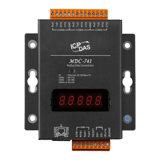
2.2. Appearance Connectors: COM3 ~ COM8 LED Indicator Configuration Display 組態設定顯示器 Connectors: Power COM2 Reset Ethernet Port COM1 LED Indicator The LED is used as a heartbeat indicator and slows to approximately one flash per second. Ethernet Port The MDC-700 is equipped with a RJ45 port for Ethernet LAN connection. - Page 9 Power Connector Configuration Display MDC-700 includes a 5-digit 7-Segment LED display to indicate configuration in a module as below: The IP address for the MDC-700 11111. (192.168.255.1) 1. 192 2. 168 3. 255 Modbus TCP communication settings 22222.
- Page 10 Reset Shorting the RESET pin to GND pin over 3 seconds can reset the IP/Subnet Mask/Gateway addresses to the factory default settings. Over 3 seconds to restore factory default settings Copyright © 2014 ICP DAS Co., Ltd. All Rights Reserved. ∗ E-mail: service@icpdas.com - 10 -...
-
Page 11: Pin Assignments
2.3. Pin Assignments MDC-711 Terminal Assignment CTS1 RTS1 COM1 RxD1 TxD1 RESET COM2 (R)+Vs (B)GND Copyright © 2014 ICP DAS Co., Ltd. All Rights Reserved. ∗ E-mail: service@icpdas.com - 11 -... - Page 12 MDC-714/MDC-714i COM3, COM4 and COM5 of MDC-714i are provided with 2500 VDC high voltage isolation protection. Terminal Terminal Assignment Assignment DATA+ COM5 DATA- CTS1 DATA+ RTS1 COM4 COM1 DATA- RxD1 TxD1 RESET COM2 DATA+ (R)+Vs COM3 DATA- (B)GND MDC-741...
- Page 13 MDC-771 Terminal Terminal Assignment Assignment COM8 COM7 CTS1 COM6 RTS1 COM1 RxD1 COM5 TxD1 RESET COM4 COM2 (R)+Vs COM3 (B)GND Copyright © 2014 ICP DAS Co., Ltd. All Rights Reserved. ∗ E-mail: service@icpdas.com - 13 -...
-
Page 14: Wiring Connections
2.4. Wiring Connections RS-232 Wiring 3-wire Connection Wiring 5-wire Connection Wiring RS-485 Wiring Copyright © 2014 ICP DAS Co., Ltd. All Rights Reserved. ∗ E-mail: service@icpdas.com - 14 -... -
Page 15: Dimensions
2.5. Dimensions Unit: mm Front View Left Side View Top View Rear View Bottom View Copyright © 2014 ICP DAS Co., Ltd. All Rights Reserved. ∗ E-mail: service@icpdas.com - 15 -... -
Page 16: Mounting The Hardware
2.6. Mounting the Hardware Wall/Panel mounting Step 1: Install the four mounting screws into the 4 keyhole mounting holes. Step 2: Fasten the screws securely. DIN Rail mounting Step 1: Align the screw holes of the DIN-rail clip with the holes on the back side of the module, and then fasten the screws securely. - Page 17 Step 2: Hook upper tab over upper flange of DIN rail. Step 3: Tilt the module toward DIN rail until it snaps securely to DIN rail Copyright © 2014 ICP DAS Co., Ltd. All Rights Reserved. ∗ E-mail: service@icpdas.com - 17 -...
-
Page 18: Getting Started
3. Getting Started A new MDC-700 comes with a default IP address of 192.168.255.1; therefore, a valid IP address should be assigned for the module to join your network. Then you can configure the MDC module from its web user interface. The factory default settings IP Address Subnet Mask... - Page 19 STEP 2: Set the IP configuration on your computer. If the MDC module is new with default IP address of 192.168.255.1, your pc should pick up an IP address in the range of 192.168.255.2 to 192.168.255.253 that is not in use. NOTE Details on how to change the IP address on your computer depend upon the type architecture and operating system you are using.
- Page 20 STEP 5: Enter your username and password to log in to the MDC module. 1. Enter your username 2. Enter your password 3. Click LOGIN STEP 6: Choose a valid IP address of the network for your MDC-700 module Scroll down to Ethernet Configuration section, input the IP/Subnet mask and Gateway addresses, and then click “Apply”.
- Page 21 STEP 7: After the success message is displayed, restore the IP address of your computer, log in the MDC again via its new IP address. NOTE The IP/Subnet mask/Gateway modified in a MDC-700 can be reset to factory defaults by shorting the RESET pin to GND pin over 3 seconds.
-
Page 22: Configuration
4. Configuration The necessary configuration for Modbus TCP/Modbus RTU communication and polling definition is handled by a single file named “config.csv”. Just follow the easy-to-use format defined in the config.csv file to edit the configuration parameters and import the new file via a simple mouse-click, the data on connected Modbus RTU slave devices can be accessed via Ethernet. -
Page 23: Exporting And Importing Config.csv File
4.1. Exporting and importing config.csv file Open the web browser and enter the IP address of the MDC-700. Any standard browser such as Mozilla Firefox, Internet Explorer or Google Chrome can be used to access the web interface. Exporting the config.csv file STEP 1: Scroll down the web page to the “Import/Export Config.csv”... - Page 24 Importing the config.csv file STEP 1: Scroll down the web page to the “Import/Export Config.csv” section. STEP 2: Click CHOOSE FILE, then select your config.csv file. STEP 3: Click IMPORT to import the config.csv file to the MDC-700.. After the success message is displayed, waiting 10 seconds for reloading the web page or click RELOAD NOW to refresh the page immediately RELOAD NOW Copyright ©...
-
Page 25: Editing The Config.csv File
4.2. Editing the config.csv file The MDC module is configured by a config.csv file to work with your master and RTU slave devices. The Comma Separated Values (CSV) files can be viewed and edited in spreadsheet applications like Microsoft Excel, or in any text editor, in which the comma character (,) typically separates each field of text. - Page 26 Modbus Connection In Modbus Connection section, you can configure the Modbus ID of the MDC-700 and the TCP port number for Modbus TCP communication. TCPPort ModbusID TCPPort: Defines the TCP/IP Port number, in the example set to 502. (Default value) ModbusID: Defines the Modbus ID of the MDC-700, in the example set to 1.
- Page 27 COM Port Configuration The COM Port Configuration is used to configure the parameters for Modbus communication connection between the MDC-700 and Modbus RTU slave devices. NOTE Only one set of configuration settings is allowed for each COM port. # ComPortNo BaudRate DataBit Parity StopBit Timeout PollDelay OperatingMode 115200 Master 115200...
- Page 28 Polling Definition The Polling Definition is used to define Modbus commands to read data from the slave devices. Before attempting to configure the parameters for the Polling Definition, be sure to check the COM port number that the target device is connected to, the Modbus ID setting for the target device, and the function code, starting address, and the quantity for reading data.
- Page 29 NOTE The maximum number of all the polling definitions is 250. The MDC-700 provides 9600 internal Modbus registers each table (DI/DO/AI/AO) to hold data collected from the RTU slave devices. The Modbus ID for the MDC-700 is defined in Modbus Connection section. ...
- Page 30 Displaying Comments for Polling Definition After firmware 2.00.001 released in 2021, users can annotate polling definitions by adding comments in the field after each definition. In spreadsheet software In text editor Copyright © 2014 ICP DAS Co., Ltd. All Rights Reserved. ∗ E-mail: service@icpdas.com - 30 -...
- Page 31 Displaying Comments for Polling Definitions on MDC-700 web page Enter the note text in the field after its related definition. Text starts with a semicolon will be displayed on the MDC-700 web page (up to 48 characters with spaces), while text after the second semicolon will not be displayed.
-
Page 32: Mdc-700 Web Interface
5. MDC-700 Web Interface Go to the web interface at http://xxx.xxx.xxx.xxx, where xxx.xxx.xxx.xxx is the IP address in your MDC-700. Any standard browser such as Mozilla Firefox, Internet Explorer or Google Chrome can be used to access the MDC-700. The MDC-700 web interface includes the following sections: 1. - Page 33 Modbus Connection In the Modbus Conncetion section, it provides the scan time information for each COM port (available in firmware 1.08 and later). The Master device can refer to the scan time to extend or shorten the time interval for each requesting data command. Current Scan Time MAX.
- Page 34 Connection Configuration The Connection Configuration section provides the configuration information including Modbus ID, Modbus TCP port on the MDC-700, and Baud Rate. Data Format, Response Timeout, Delay Between Polls, Operation Mode settings for each COM port. Modbus ID Modbus TCP Port COM Port Settings ...
- Page 35 Authentication / User Management In the Authentication / User Management section, you can change the username and password of the administrator account, create a read only user account, and set security questions and answers for password recovery. Changing the username and password of the administrator Enter new username and/or password and click SAVE Click SAVE Username...
- Page 36 Creating a read only user account In order to avoid unexpected changes to the settings of a running MDC-700 module, you can create a user account with only read permission, and specify which information can be accessed. Click SAVE Enable the checkbox Enter Username Enter Password You will see a success message displayed.
- Page 37 Specifying the information for the read-only user account If the user account is created without specifying which information can be accessed, the content that can be accessed is shown as the picture below. Copyright © 2014 ICP DAS Co., Ltd. All Rights Reserved. ∗ E-mail: service@icpdas.com - 37 -...
- Page 38 The section for specifying information for the read only user to access is enabled only when the checkbox for user account has been activated. Check the checkbox for allowing the information to be accessed by the user account, the example of information checked will be shown in the next line of "What information should be allowed for the user to see".
- Page 39 The success message will be displayed. Log in with the user account, now the information checked is displayed on the page. Copyright © 2014 ICP DAS Co., Ltd. All Rights Reserved. ∗ E-mail: service@icpdas.com - 39 -...
- Page 40 Setting security questions and answers The MDC-700 allows you to set security questions and answers that you can use should you forget your password. Two sets of security questions and answers are provided. You can enter a maximum of 38 characters in the Question field and a maximum of 14 characters in the Answer field. Note that the answer is case sensitive when it is used to log in to the MDC module.
- Page 41 How to log in to the module when you forgot your password? If you are an administrator and you have forgotten your password, click Forgot Password? Enter your username and click CONTINUE Copyright © 2014 ICP DAS Co., Ltd. All Rights Reserved. ∗ E-mail: service@icpdas.com - 41 -...
- Page 42 Select your question from the drop down menu Enter the answer (case sensitive) and click CONTINUE. Now you have logged into your account on the module. Copyright © 2014 ICP DAS Co., Ltd. All Rights Reserved. ∗ E-mail: service@icpdas.com - 42 -...
- Page 43 Import/Export Config.csv and file validation You can import/export the config.csv file in this section. Refer to section 4.1 for the detailed steps. File validation success message After firmware 2.00.001, MDC-700 provides the function of validating the polling definitions in its config.csv file.
- Page 44 Fimware Version/OS Version and MAC Address Information about Firmware version, OS version and MAC address is located in the footer. Logging out The current username is displayed at the right of the connection status. Click LOGOUT to log out from the MDC-700.
-
Page 45: Troubleshooting
6. Troubleshooting In this chapter, we will explain how to troubleshoot the communication problems. Possible causes of TIMEOUT Situation #1: The slave device is not active or the transfer function of the slave site may fail. Solution: Check the slave device is powered up and the communication function is enabled. ... - Page 46 Situation #5: An incorrect ID of the Modbus slave device is being specified. Solution: Check and fix the difference of ID number between the polling definition and the slave device. Situation #6: The Timeout or PollDelay setting is not long enough. Solution: Lengthen the Timeout or PollDelay setting until it is suitable for communication with the slave device.
-
Page 47: Faq
7. FAQ Q1: What are the maximum numbers of polling definition and local register? A1: The maximum number of polling definition in a MDC-700 is 250, each definition can access up to 125 registers. Each of the four tables (DI/DO/AI/DO) can store up to 9600 registers for polled data. Q2: What is the maximum number of registers can be accessed in one Modbus command? A2: By following the Modbus protocol, the maximum amount of registers that one command can... -
Page 48: Q3: How Are The Local Registers Mapped To The Polled Data In A Mdc-700
Q3: How are the local registers mapped to the polled data in a MDC-700? A3: Only the function code 01/02/03/04 can be used in the polling definition section 01: Read Coil Status (Read DO) 02: Read Input Status (Read DI) 03: Read Holding Registers (Read AO) 04: Read Input Registers (Read AI) Refer to the example below,... - Page 49 The local registers mapping is listed on the main page of the MDC-700 module. Slave device ID followed by register The mapped addresses on MDC-700 addresses for each polling definition The MDC-700 allows users to enable/disable a polling definition by changing the first field of the polling definition section in the config.csv file.
-
Page 50: Q4: How To Write Data To Output Channels On A Modbus Rtu Slave Device
Q4: How to write data to output channels on a Modbus RTU slave device? Step 1: Edit the polling definition for the output channels with read function code in the config.csv file. (For example, use 01 to read DO channels, 03 to read AO channels) # UseComPort SlaveModbusID FunctionCode RegStart RegCount Timeout Preset... -
Page 51: Q5: How To Read The Status Of Each Connection
Q5: How to read the status of each connection? A5: The status for each connection is saved in the sequence of polling definition from local register address 39600. The maximum number of polling definition in the config.csv file is 250, so the available address for the connection status is from 39600 to 39849. -
Page 52: Q6: How To Update Firmware
Q6: How to update firmware? A6: The upgrade procedure of the firmware consists of the following main steps: Install the MiniOS7 Utility on your computer Upload the latest firmware to MDC-700 through the MiniOS7 Utility Check the firmware version and the configuration settings via web interface Here we will introduce how to update firmware of the MDC-700 step-by-step. - Page 53 2. Upgrade Firmware using the MiniOS7 The firmware update requires a TCP/IP connection. Connect the MDC-700 to a network whenever possible. Step 1: Use an Ethernet cable to connect the MDC-700 to the computer After plugging the Ethernet cable, the Link/Act and 10/100 indicator LEDs come on or start flashing to indicate a connection was made.
- Page 54 Step 3: Look for the connector symbol at the upper right-hand corner of the MiniOS7 Utility to ensure the connection is made Connection successful If the connection fails, make sure that: An Ethernet cable is connected securely to both the MDC-700 and your computer ...
- Page 55 Step 5: Upload the firmware file to MDC-700 Right-click on the MDC7XXV109.HEX file and select Upload from the menu. Step 6: Wait until the firmware update is finished, and then power cycle the MDC-700. 3. Check the Firmware Version Step 1: Open a web browser and enter the IP address of the MDC-700 in the URL. Step 2: Check the version information at the bottom of the page.
-
Page 56: Q7: Why Does The Page Not Display Correctly In My Browser
Q7: Why does the page not display correctly in my browser? A7: After the firmware version 1.08 was released, the MDC module adopts HTML5 in place of Flash. HTML5 is supported in all modern browsers, but not the older browsers like IE8 and below. If your browser does not support the HTML5, it cannot render the page correctly. -
Page 57: Appendix
Appendix The differences between Firmware V. 1.08 and V. 2.00 Firmware V. 1.08 Firmware V. 2.00 Authentication / User Management Security authentication Account and password login Security question and answer login Access permission management - One Full Access Administrator and one view-only user Polling Definition Definition validation... -
Page 58: Revision History
- Modified the description for web page for firmware V1.08 1.0.3 2018/02 - Added Section 2.5. Mounting the Hardware. - Added specifications of MDC-714, MDC-714i and MDC-771i 1.0.4 2021/08 - Added the description for new functions in firmware v. 2.00 Copyright ©...
Need help?
Do you have a question about the MDC-714i and is the answer not in the manual?
Questions and answers