ICP DAS USA MDC-700 Series User Manual
Hide thumbs
Also See for MDC-700 Series:
- User manual (34 pages) ,
- Quick start (4 pages) ,
- Quick start (4 pages)

Related Manuals for ICP DAS USA MDC-700 Series


Summary of Contents for ICP DAS USA MDC-700 Series
- Page 1 MDC‐700 Series User Manual Feb. 2018, Version 1.0.3 Written by Liam Lin ...
- Page 2 Warranty All products manufactured by ICP DAS are warranted against defective materials for a period of one year from the date of delivery to the original purchaser. Warning ICP DAS assumes no liability for damages consequent to the use of this product. ICP DAS reserves the right to change this manual at any time without notice. The information furnished by ICP DAS is believed to be accurate and reliable. However, no responsibility is assumed by ICP DAS for its use, nor for any infringements of patents or other rights of third parties resulting from its use. Copyright Copyright © 2014 by ICP DAS. All rights are reserved. Contact Us If you have any questions, please feel free to contact us via email at: Service@icpdas.com Copyright © 2014 ICP DAS Co., Ltd. All Rights Reserved. ∗ E‐mail: service@icpdas.com ‐ 2 ‐ ...
-
Page 3: Table Of Contents
Contents 1. Introduction ............................4 2. Hardware Information ........................7 2.1. Appearance..........................7 2.2. Specifications ......................... 10 2.3. Wiring Connections ....................... 11 2.4. Dimensions ..........................12 2.5. Mounting the Hardware ......................13 3. Configuration ............................ 15 3.1. Assigning an IP address to MDC‐700 ..................16 3.2. Editing the config.csv file ....................... 18 3.3. Importing/exporting the config.csv file................. 23 4. HMI Web Interface ........................... 25 5. Troubleshooting ..........................29 6. FAQ..............................31 Q1: What are the maximum numbers of polling definition and local register?...... -
Page 4: Introduction
1. Introduction The MDC‐700 series module is a Modbus Data Concentrator which can concentrate data from several Modbus RTU slave devices with RS232/RS‐485 interface and allows Modbus TCP masters to read/write data via Ethernet/LAN. The Modbus master can use one Modbus command to get all data on those Modbus RTU slave devices via the MDC‐700 concentrator. In other words, through the help of a MDC‐700 module, the Modbus RTU slave devices can be accessed over Ethernet with better read and write performance. The MDC‐700 series module has the ability to perform up to 250 Modbus RTU commands to read/write data from/to Modbus RTU slave devices and allows up to 8 Modbus TCP masters to get the polled data. The support for Modbus TCP protocol makes the MDC‐700 well integrated into PC‐based applications such as SCADA (Supervisor Control and Data Acquisition) and HMI (Human Machine Interface) programs. Copyright © 2014 ICP DAS Co., Ltd. All Rights Reserved. ∗ E‐mail: service@icpdas.com ‐ 4 ‐ ... - Page 5 Features HTML5 Web‐based User Interface HTML5 is the latest version of the HTML markup language. It is supported by most current browsers including Mozilla Firefox, Apple Safari, Google Chrome and so on. For the reason, the Web‐Based user interface for the MDC‐700 is accessible from a wide variety of devices anywhere. Users can configure the module and monitor connection status of each polling definition through their smart phones, tablets or desktops without a line of code. Great Capability of Shared Memory The MDC‐700 series module can perform up to 250 polling definitions. And the internal shared memory has four tables to store the polled AI, AO, DI and DO data. Each table can store up to 9600 registers. Copyright © 2014 ICP DAS Co., Ltd. All Rights Reserved. ∗ E‐mail: service@icpdas.com ‐ 5 ‐ ...
- Page 6 Config.CSV to Ease Hard Work of Editing a lot of Definition The Modbus polling definition is defined in a Config.CSV file. Editing/checking a lot of polling definitions is a hard work and it may be making mistakes. A CSV format file can ease the work by using Excel. Furthermore, the built‐in web server allows users to import/export the Config.CSV via a simple mouse‐click action. Support for Modbus TCP Master and Modus RTU Master The MDC‐700 can be accessed by Modbus TCP Master and Modus RTU Master. Changing the mode for a COM port from Master to Slave allows a connected Modus RTU Master to read/write data from/to the Modbus RTU slave devices on the other COM ports. Copyright © 2014 ICP DAS Co., Ltd. All Rights Reserved. ∗ E‐mail: service@icpdas.com ‐ 6 ‐ ...
-
Page 7: Hardware Information
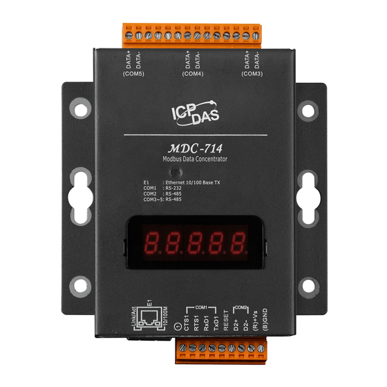
2. Hardware Information 2.1. Appearance Connectors: (For MDC ‐714/MDC714) COM3 COM4 COM5 LED Indicator Configuration Display Connectors: Power COM2 Reset Ethernet Port COM1 LED Indicator The LED is used as a heartbeat indicator and slows to approximately one flash per second. Ethernet Port The MDC‐700 is equipped with a RJ45 port for Ethernet LAN connection. When 100BASE‐TX is operating, the 10/100M LED is lit orange. When 10BASE‐T is operating or the machine is ... - Page 8 Power Connector Configuration Display MDC‐700 includes a 5‐digit 7‐Segment LED display to indicate configuration in a module as below: The IP address for the MDC‐700 11111. (192.168.255.1) 1. 192 2. 168 ...
- Page 9 Reset Shorting the RESET pin to GND pin over 3 seconds ca n reset the IP/Subnet Mask/Gateway addresses to the factory default settings. Copyright © 2014 ICP DAS Co., Ltd. All Rights Reserved. ∗ E‐mail: service@icpdas.com ‐ 9 ‐ ...
-
Page 10: Specifications
2.2. Specifications MDC‐711 MDC‐714 MDC‐741 Ethernet Port x1, 10/100 Base‐TX Protocol Modbus/TCP Slave Max. Connection 8 COM Port RS‐232 x1, (TXD, RXD, RTS, CTS, GND) x4, (TXD, RXD, RTS, CTS, GND) RS‐485 x1, (Data+, Data‐) x4, (Data+, Data‐) x1, (Data+, Data‐) Baud Rate 1200, 2400, 4800, 9600, 19200, 38400, 57600, 115200 (bps) Data Format N81, E81, O81 Protocol Modbus RTU Master Max. Node 32 nodes for each RS‐485 port Polling Definition 250 definitions for all RS‐232/485 ports Shared Memory 9600 registers for each of AI, AO, DI and DO Data System System 5‐Digit 7 Segment LED Yes, to display IP address Display System LED Indicator Yes, to display heartbeat Mechanical ... -
Page 11: Wiring Connections
2.3. Wiring Connections RS‐232 Wiring 3‐wire Connection Wiring 5‐wire Connection Wiring RS‐485 Wiring Copyright © 2014 ICP DAS Co., Ltd. All Rights Reserved. ∗ E‐mail: service@icpdas.com ‐ 11 ‐ ... -
Page 12: Dimensions
2.4. Dimensions Unit: mm Front View Left Side View Top View Rear View Bottom View Copyright © 2014 ICP DAS Co., Ltd. All Rights Reserved. ∗ E‐mail: service@icpdas.com ‐ 12 ‐ ... -
Page 13: Mounting The Hardware
2.5. Mounting the Hardware Wall/Panel mounting Step 1: Install the four mounting screws into the 4 keyhole mounting holes. Step 2: Fasten the screws securely. DIN Rail mounting Step 1: Align the screw holes of the DIN‐rail clip with the holes on the back side of the module, and then fasten the screws securely. 1 ... - Page 14 Step 2: Hook upper tab over upper flange of DIN rail. Step 3: Tilt the module toward DIN rail until it snaps securely to DIN rail 2 Copyright © 2014 ICP DAS Co., Ltd. All Rights Reserved. ∗ E‐mail: service@icpdas.com ‐ 14 ‐ ...
-
Page 15: Configuration
3. Configuration The necessary configuration for Modbus TCP communication, Modbus RTU communication and polling definition is handled by a single file named “config.csv”. Just follow the easy‐to‐use format defined in the config.csv file and import the new config.csv file via a simple mouse‐click on the main page of the MDC‐700, the data on those Modbus RTU slave devices can be accessed over an Ethernet. Only the Function code 01/02/03/04 can be used in the config.csv file: 01: Read Coil Status (Read DO) 02: Read Input Status (Read DI) 03: Read Holding Registers (Read AO) 04: Read Input Registers (Read AI) If you would like to write data to a digital or analog output channel on a Modbus RTU slave device, the output channel needs be mapped with a local register address in the MDC‐700 by editing the polling definition with using corresponding read function code (01 or 03). Refer to Section 6. FAQ‐Q4 for more detailed steps. The following section will help you to set up your MDC‐700 module. After completing the following steps, you can obtain configuration and other information related to the MDC module and associated slave devices in your browser. Basic operating procedure Step 1: Assign a valid IP address to the MDC‐700. Step 2: Edit the config.csv file. Note that before editing this file, you should confirm the parameter value for any associated Slave devices. Step 3: Upload the config.csv file to the MDC‐700. Copyright © 2014 ICP DAS Co., Ltd. All Rights Reserved. ∗ E‐mail: service@icpdas.com ‐ 15 ‐ ... -
Page 16: Assigning An Ip Address To Mdc-700
3.1. Assigning an IP address to MDC‐700 The MDC‐700 is an Ethernet device, which comes with a default IP address of 192.168.255.1; therefore, you must first assign a valid IP address of your network to the module. To access the MDC‐700 by using web‐based interface, you have to know the IP address setting in the module. STEP 1: Connect the PC and MDC‐700 module to an Ethernet Hub/Switch, and power on all the devices. You can also connect a MDC‐700 to PC directly with an Ethernet cable. STEP 2: Set the IP configuration on your computer. If the MDC module is new with using the default IP address of 192.168.255.1, you must chose an IP address for the computer in the range of 192.168.255.2 – 192.168.255.253 that is not already in use. NOTE: Details on how to change the IP address on your computer depend upon the type architecture and operating system you are using. Use the Help and Support functionality on your computer and search for "IP Addressing". STEP 3: Open a web browser and go to the website at http://192.168.255.1, where 192.168.255.1 is the IP address in your MDC module. Copyright © 2014 ICP DAS Co., Ltd. All Rights Reserved. ∗ E‐mail: service@icpdas.com ‐ 16 ‐ ... - Page 17 STEP 4: Confirm the connection status icon is open on the page. Denotes the connection between the computer and the MDC‐module is open. Denotes the connection between the computer and the MDC‐module is failed. STEP 4: Choose a valid IP address of the network for your MDC‐700 module Scroll down to ‘Ethernet Configuration’ section, input the IP/Subnet mask and Gateway addresses and click on the “Apply” button. Make sure that the IP address you pick is not currently in use by another device on the network. ...
-
Page 18: Editing The Config.csv File
3.2. Editing the config.csv file The MDC module is configured by a config.csv file to work with your master and RTU slave devices. The Comma Separated Values (CSV) files can be viewed and edited in spreadsheet applications like Microsoft Excel, or in any text editor, in which the comma character (,) typically separates each field of text. In a text editor, it looks like this: The file name “config.csv” can not be changed; it contains four main sections that need to be edited: (1) Modbus Connection, (2) Module information, (3) COM Port Configuration and (4) Polling Definition. Each section starts with a “#” character; follows are names for parameters in this section. A row starting with a “*” character is a set of settings in a section. NOTE: The name for each parameter can not be changed. You can make a copy of the config.csv file in three ways and modify it to meet your requirements: 1. Export the config.csv file in your MDC‐700. (See 3.3. Importing/exporting the config.csv file) 2. Download the file from http://ftp.icpdas.com/pub/cd/8000cd/napdos/modbus/mdc700/firmware/. Copyright © 2014 ICP DAS Co., Ltd. All Rights Reserved. ∗ E‐mail: service@icpdas.com ‐ 18 ‐ ... - Page 19 Modbus Connection The Modbus Connection section is used to configure the Modbus ID of the MDC‐700 and the TCP port number for Modbus TCP communication. # TCPPort ModbusID * 502 TCPPort: Defines the TCP/IP Port number, in the example set to 502. (Default value) ModbusID: Defines the Modbus ID of the MDC‐700, in the example set to 1. (Default value) Module Information The Module Information section is used to record auxiliary description for the MDC‐700. It will be displayed on the main page of the MDC‐700, and can be used to identify one MDC‐700 from the others. # ModuleInfo * this is my data concentrator ModuleInfo: Defines the auxiliary description for the MDC module. The string constant has a maximum length of 32 characters. ...
- Page 20 COM Port Configuration The COM Port Configuration is used to configure the parameters for the RS‐485 Modbus communication connection between the MDC‐700 and the RTU slave devices. NOTE: Only one set of configuration settings is allowed for each COM port. # ComPortNo BaudRate DataBit Parity StopBit Timeout PollDelay OperatingMode * 1 115200 8 20 Master * 2 115200 8 20 Master * 3 115200 8 20 Master * 4 115200 8 20 Master * ...
- Page 21 Polling Definition The Polling Definition is used to define Modbus commands to read data from the slave devices. Before attempting to configure the parameters for the Polling Definition, be sure to check the COM port number that the target device is connected to, the Modbus ID setting for the target device, and the function code, start address, and the quantity for reading data. # UseComPort SlaveModbusID FunctionCode RegStart Timeout Preset RegCount Addr EventProcess Value * 1 1 2 * 2 2 2 * 3 3 2 * 4 4 2 * 5 5 2 Each Polling Definition consists of 8 parameters listed as below: ...
- Page 22 NOTE: NOTE: The maximum number of all the polling definitions is 250. The maximum number of all the polling definitions is 250. The MDC‐700 provides 9600 internal Modbus registers each table (DI/DO/AI/AO) to hold data The MDC‐700 provides 9600 internal Modbus registers each table (DI/DO/AI/AO) to hold data collected from the RTU slave devices. collected from the RTU slave devices. The Modbus ID for the MDC‐700 is defined in Modbus Connection section. The Modbus ID for the MDC‐700 is defined in Modbus Connection section. By setting different types for a polling definition to retain register space mapped for specific By setting different types for a polling definition to retain register space mapped for specific devices, or to release those space mapped but reserve the definition, the main program on the devices, or to release those space mapped but reserve the definition, the main program on the Modbus master device can be applied in different applications where users would like to change Modbus master device can be applied in different applications where users would like to change or stop some devices without modification or with minimum level of modification. or stop some devices without modification or with minimum level of modification. The TimeoutEventProcess and the PresetValue parameters are only available to firmware The TimeoutEventProcess and the PresetValue parameters are only available to firmware version 1.08 and later. If a config.csv file for firmware version 1.06 or prior is imported to a version 1.08 and later. If a config.csv file for firmware version 1.06 or prior is imported to a MDC‐700 with firmware version 1.08 or later, the TimeoutEventProcess parameter is auto set to MDC‐700 with firmware version 1.08 or later, the TimeoutEventProcess parameter is auto set to 2, and the PresetValue parameter is set to 0. 2, and the PresetValue parameter is set to 0. ...
-
Page 23: Importing/Exporting The Config.csv File
3.3. Importing/exporting the config.csv file Go to the web interface at http://xxx.xxx.xxx.xxx, where xxx.xxx.xxx.xxx is the IP address set in your MDC module. Any standard browser such as Mozilla Firefox, Internet Explorer or Google Chrome can be used to interface the module. NOTE: If you haven’t changed the default IP address in the MDC‐700, refer to “3.1. Assigning an IP address to MDC‐700” to configure it. After the import process is finished, the MDC‐700 will reboot in 5 seconds. Importing a CSV file to MDC‐700 STEP 1: Scroll down to the Import/Export Config.csv section of the page, click the CHOOSE FILE button, and then select your config.csv file. STEP 2: Click on the Import button to import the config.csv file to the MDC‐700. ... - Page 24 Exporting a CSV file from MDC‐700 STEP 1: Click on the Export button to export the config.csv file from the MDC‐700. The config.csv file will be exported to the download directory configured in the web browser. Copyright © 2014 ICP DAS Co., Ltd. All Rights Reserved. ∗ E‐mail: service@icpdas.com ‐ 24 ‐ ...
-
Page 25: Hmi Web Interface
4. MDC‐700 Web Interface Go to the web interface at http://xxx.xxx.xxx.xxx, where xxx.xxx.xxx.xxx is the IP address in your MDC‐700. Any standard browser such as Mozilla Firefox, Internet Explorer or Google Chrome can be used to interface the MDC‐700. The MDC‐700 web page includes the following sections: 1. The connection status between the user device and the MDC‐700 2. The connection information for each polling definition 3. The communication configuration information on the MDC‐700 4. Ethernet configuration 5. Importing/exporting the config.csv file 6. OS version, firmware version and MAC address information Connection status between your device and the MDC‐700 Module Name Auxiliary Description Connection Status Denotes the connection is successfully established Denotes the connection is failed ... - Page 26 Modbus Connection In the Modbus Conncetion section (on the MDC‐700 with firmware version 1.08 and later), it provides the scan time information for each COM port. The Master device can refer to the scan time to extend or shorten the time interval for each requesting data command. Current Scan Time MAX. Scan Time Min. Scan Time Reset Record Expand the polling definitions by clicking on the [+COMn], information including the polling definition number, SlaveModbusID, Starting Address of Register and Count of Register on both slave client and MDC‐700, and the connection status are provided. Connection Status: Good Connection Failed ...
- Page 27 Connection Configuration The Connection Configuration section provides the configuration information including Modbus ID, Modbus TCP port on the MDC‐700, and Baud Rate. Data Format, Response Timeout, Delay Between Polls, Operation Mode settings for each COM port. Modbus ID Modbus TCP Port COM Port Settings Ethernet Configuration In this section you can obtain or set the Ethernet Configuration. To change the Ethernet parameters, you just need to input the valid IP, Subnet mask and Gateway addresses and then click APPLY. Copyright © 2014 ICP DAS Co., Ltd. All Rights Reserved. ∗ E‐mail: service@icpdas.com ‐ 27 ‐ ...
- Page 28 Import/Export Config.csv You can import/export the config.csv file in this section. Refer to Section 3.3 for the detailed steps. Fimware Version/OS Version and MAC Address The Firmware version, OS version and MAC address for the MDC‐700 are commented at the bottom of the page. Copyright © 2014 ICP DAS Co., Ltd. All Rights Reserved. ∗ E‐mail: service@icpdas.com ‐ 28 ‐ ...
-
Page 29: Troubleshooting
5. Troubleshooting In this chapter, we will explain how to troubleshoot the communication problems. Possible causes of TIMEOUT Situation #1: The slave device is not active or the transfer function of the slave site may fail. Solution: Check the slave device is powered up and the communication function is enabled. Situation #2: The COM port number to which the slave device is connected is not the same with the UseComPort setting in the polling definition. Solution: Connect the slave device to the COM port number that is defined in the polling definition, or fix the UseComPort parameter to the virtual COM port number that the slave device is connected to. Situation #3: The wiring for communication is wrong. Solution: Exchange the D+ and D‐ wiring of RS‐485 connection, or exchange the Rx and Tx wiring of RS‐232 connection, and check the GND pin on the slave device is properly connected to the MDC‐700. Situation #4: An incorrect Baud Rate or/and Data Format setting is being specified. Solution: Check and fix the difference of the Baud Rate and Data Format settings between the polling definition and the slave device. ComPortNo BaudRate DataBit Parity StopBit Timeout PollDelay Operating Mode 1 9600 8 100 Master 2 9600 8 3000 1000 ... - Page 30 Situation #5: An incorrect ID of the Modbus slave device is being specified. Solution: Check and fix the difference of ID number between the polling definition and the slave device. Situation #6: The Timeout or PollDelay setting is not long enough. Solution: Lengthen the Timeout or PollDelay setting until it is suitable for communication with the slave device. ComPortNo BaudRate DataBit Parity StopBit Timeout PollDelay Operating Mode 1 9600 8 100 Master 2 9600 8 3000 1000 Master 3 9600 8 3000 1000 Master 4 9600 8 100 Master 5 9600 8 ...
-
Page 31: Faq
6. FAQ Q1: What are the maximum numbers of polling definition and local register? A1: The maximum number of polling definition in a MDC‐700 is 250, each definition can access up to 125 registers. Each of the four tables (DI/DO/AI/DO) can store up to 9600 registers for polled data. Q2: What is the maximum number of registers can be accessed in one Modbus command from a Modbus master device? A2: By following the Modbus protocol, the maximum amount of registers that one command can access is 255 of function code 01 and 02, and 126 of function code 03 and 04. Copyright © 2014 ICP DAS Co., Ltd. All Rights Reserved. ∗ E‐mail: service@icpdas.com ‐ 31 ‐ ... -
Page 32: Q3: How Are The Local Registers Mapped To The Polled Data In A Mdc-700
Q3: How are the local registers mapped to the polled data in a MDC‐700? A3: Only the function code 01/02/03/04 can be used in the polling definition section in config.csv file. 01: Read Coil Status (Read DO) 02: Read Input Status (Read DI) 03: Read Holding Registers (Read AO) 04: Read Input Registers (Read AI) Refer to the example below, # UseComPort SlaveModbusID FunctionCode RegStart Timeout Preset RegCount Addr EventProcess Value * 1 1 2 * 1 1 2 * 2 1 2 * 2 2 2 * 2 ... - Page 33 The local registers mapping is listed on the main page of the MDC‐700 module. Slave device ID followed by register addresses for each polling definition The mapped addresses on the MDC‐700 The MDC‐700 allows users to enable/disable a polling definition by changing the first field of the polling definition section in the config.csv file. There are three types that users can use: “*”: Asterisk symbol means that this is a valid polling definition. The MDC‐700 will assign local register for data defined in the definition and save the polled data to the mapping local register. “‐”: Minus sign means that this is a disabled polling definition. The MDC‐700 will assign local register for data defined in the definition but will not poll the data. “”: Empty means that this is a null polling definition. The MDC‐700 will neither assign local register for data defined in the definition nor poll data. # UseComPort SlaveModbusID FunctionCode RegStartAddr RegCount * 1 ...
-
Page 34: Q4: How To Write Data To Output Channels On A Modbus Rtu Slave Device
Q4: How to write data to output channels on a Modbus RTU slave device? A4: Step 1: Edit the polling definition for the output channels with read function code in the config.csv file. (For example, use 01 to read DO channels, 03 to read AO channels) # UseComPort SlaveModbusID FunctionCode RegStart Timeout Preset RegCount Addr EventProcess Value * 1 1 2 * 2 2 2 * 3 3 2 * 4 4 2 * 5 5 2 Step 2: Import the config.csv file into the MDC‐700, wait the MDC‐700 reboot in 5 seconds, and ... -
Page 35: Q5: How To Read The Status Of Each Connection
Q5: How to read the status of each connection? A5: The status for each connection is saved in the sequence of polling definition from local register address 39600. The maximum number of polling definition in the config.csv file is 250, so the available address for the connection status is from 39600 to 39849. A Modbus master use function code 04 to read the status, up to 126 register of status can be read in one command. For example, the status of the graph shown above is presented as the third column in the following table. Def. number Address Status Status display on web page Def.#001 39600 0 GOOD Def.#002 39601 0 GOOD Def.#003 39602 0xFFFF TIMEOUT Def.#004 39603 0x8201 ERROR: ILLEGAL FUNCTION Def.#005 39604 0 GOOD Def.#006 ... -
Page 36: Q6: How To Update Firmware
Q6: How to update firmware? A6: The upgrade procedure of the firmware consists of the following main steps: Install the MiniOS7 Utility on your computer Upload the latest firmware to MDC‐700 through the MiniOS7 Utility Check the firmware version and the configuration settings via web interface Here we will introduce how to update firmware of the MDC‐700 step‐by‐step. 1. Install MiniOS7 Utility STEP 1: Download the installation file of the MiniOS7 Utility to your computer The installation file can be obtained from: http://ftp.icpdas.com/pub/cd/8000cd/napdos/minios7/utility/minios7_utility/old/ Step 2: Run the downloaded file to start the installation process. It will lead you through the installation step by step Step 3: After the installation is finished, the icon named “MiniOS7 Utility Ver 3.27” will appear on the desktop and the Program sub‐menu “ICPDAS” of the start menu Copyright © 2014 ICP DAS Co., Ltd. All Rights Reserved. ∗ E‐mail: service@icpdas.com ‐ 36 ‐ ... - Page 37 2. Upgrade Firmware using the MiniOS7 The firmware update requires a TCP/IP connection. Connect the MDC‐700 to a network whenever possible. Step 1: Use an Ethernet cable to connect the MDC‐700 to the computer After plugging the Ethernet cable, the Link/Act and 10/100 indicator LEDs come on or start flashing to indicate a connection was made. Step 2: Establishing a connection between the MiniOS7 Utility and the MDC‐700 Launch the MiniOS7 Utility and then select New Connection on the Connection menu. 1 On the “Connection” tab of the “Connection” dialog, select “TCP” from the dropdown list, type the IP address of MDC‐700, and then click OK button. 2 4 Copyright © 2014 ICP DAS Co., Ltd. All Rights Reserved. ∗ E‐mail: service@icpdas.com ‐ 37 ‐ ...
- Page 38 Step 3: Look for the connector symbol at the upper right‐hand corner of the MiniOS7 Utility to ensure the connection is made Connection successful If the connection fails, make sure that: An Ethernet cable is connected securely to both the MDC‐700 and your computer The MDC‐700 is active (powered on) The IP address of MDC‐700 is correct No firewall is blocking the connection Step 4: Delete the original files from the MDC‐700 After establishing a connection, select “Erase Disk” from Command menu (or right‐click on the right of window) to delete all files existed on the MDC‐700. Step 5: Upload the firmware file to MDC‐700 Right‐click on the MDC7XXV109.HEX file and select Upload from the menu. Step 6: Wait until the firmware update is finished, and then power cycle the MDC‐700. Copyright © 2014 ICP DAS Co., Ltd. All Rights Reserved. ...
- Page 39 3. Check the Firmware Version Step 1: Open a web browser and enter the IP address of the MDC‐700 in the URL. Step 2: Check the version information at the bottom of the page. Copyright © 2014 ICP DAS Co., Ltd. All Rights Reserved. ∗ E‐mail: service@icpdas.com ‐ 39 ‐ ...
-
Page 40: Q7: Why Does The Page Not Display Correctly In My Browser
Q7: Why does the page not display correctly in my browser? A7: After the firmware version 1.08 was released, the MDC module adopts HTML5 in place of Flash. HTML5 is supported in all modern browsers, but not the older browsers like IE8 and below. If your browser does not support the HTML5, it cannot render the page correctly. It is recommended to use a newer browser. The browsers support HTML5: Windows Edge 14 or later Windows IE9/IE10/IE11 or later Google Chrome 55 or later Mozilla Firefox 50 or later Apple Safari 9.1 or later Opera 42 or later If the MDC‐700 module is running with firmware version 1.06 or earlier, the page requires the Adobe Flash Player to be installed. The latest version of the Adobe Flash Player can be downloaded by accessing the Adobe Systems Incorporated website. The following instructions will help you to install the Adobe Flash Player in your web browser. STEP 1: Go to the Adobe Flash Player Download Center The address for Adobe Flash Player Download Center is http://get.adobe.com/flashplayer/ NOTE: The Adobe Flash Player is subject to change without notice; refer to http://www.adobe.com/support/flashplayer/debug_downloads.html for the latest version of this software. STEP 2: Follow the instructions to download the installation file and install it on your PC. Copyright © 2014 ICP DAS Co., Ltd. All Rights Reserved. ∗ E‐mail: service@icpdas.com ‐ 40 ‐ ... -
Page 41: Appendix
Appendix A: The differences between Firmware V. 1.06 and V. 1.08 Firmware V. 1.06 Firmware V. 1.08 Modbus RTU Polling Definition 240 Max. 250 Max. Max. Register Count in one 64 Max. 125 Max. Polling Definition The data that Master will obtain Exception Code Exception Code, the last while timeout error is occurred correct data or the preset value selectable Web Interface Web technique Flash HTML5 Scan Time for each COM port ‐ Yes Copyright © 2014 ICP DAS Co., Ltd. All Rights Reserved. ∗ E‐mail: service@icpdas.com ‐ 41 ‐ ... -
Page 42: Revision History
Revision History Revision Date Description 1.0.0 2014/11 First released 1.0.1 2015/07 Added description for MDC‐741. Added dimensions, appearance information and Troubleshooting, FAQ 1.0.1 2015/11 sections. ‐ Modified the description for web page for firmware V1.08 1.03 2018/02 ‐ Added Section 2.5. Mounting the Hardware. Copyright © 2014 ICP DAS Co., Ltd. All Rights Reserved. ∗ E‐mail: service@icpdas.com ‐ 42 ‐ ...
Need help?
Do you have a question about the MDC-700 Series and is the answer not in the manual?
Questions and answers