
Related Manuals for Rockwell Automation ControlNet 1756-CN2


Summary of Contents for Rockwell Automation ControlNet 1756-CN2
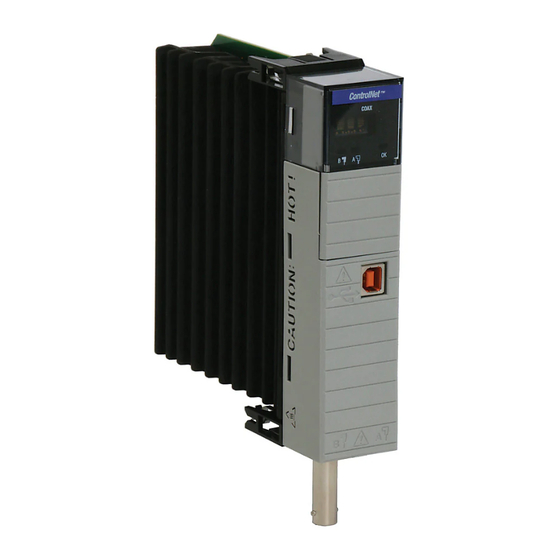
- Page 1 Installation Instructions ControlNet Modules Catalog Numbers 1756-CN2, 1756-CN2R, 1756-CN2RK, 1756-CN2RXT, 1756-CNB, 1756-CNBR, 1768-CNB, 1768-CNBR...
-
Page 2: Important User Information
If this equipment is used in a manner not specified by the manufacturer, the protection provided by the equipment may be impaired. In no event will Rockwell Automation, Inc. be responsible or liable for indirect or consequential damages resulting from the use or application of this equipment. -
Page 3: New And Updated Information
This table contains the changes made to this revision. Information Topic Page Updated artwork to illustrate module redesign Throughout document Updated EDS file and firmware download procedures Chapters 1, 2, and 3 Updated 1756 status indicators Appendix A Rockwell Automation Publication CNET-IN005C-EN-P - July 2014... - Page 4 Summary of Changes Notes: Rockwell Automation Publication CNET-IN005C-EN-P - July 2014...
-
Page 5: Table Of Contents
Additional Resources ......... 35 Rockwell Automation Publication CNET-IN005C-EN-P - July 2014... - Page 6 Network Channel Status Indicators ......53 Index Rockwell Automation Publication CNET-IN005C-EN-P - July 2014...
-
Page 7: Studio 5000 Environment
The Studio 5000 environment is the foundation for the future of Rockwell Automation engineering design tools and capabilities. This environment is the one place for design engineers to develop all of the elements of their control system. Rockwell Automation Publication CNET-IN005C-EN-P - July 2014... -
Page 8: Additional Resources
Provides declarations of conformity, certificates, and other certification details. You can view or download publications at http:/www.rockwellautomation.com/literature/. To order paper copies of technical documentation, contact your local Allen-Bradley distributor or Rockwell Automation sales representative. Rockwell Automation Publication CNET-IN005C-EN-P - July 2014... - Page 9 In addition to this publication, see the following: • Industrial Automation Wiring and Grounding Guidelines, publication 1770-4.1, for additional installation requirements. • NEMA Standard 250 and IEC 60529, as applicable, for explanations of the degrees of protection provided by enclosures. Rockwell Automation Publication CNET-IN005C-EN-P - July 2014...
- Page 10 • This equipment must be installed in an enclosure providing at least IP54 protection when applied in Zone 2 environments. • This equipment shall be used within its specified ratings defined by Rockwell Automation. • Provision shall be made to prevent the rated voltage from being exceeded by transient disturbances of more than 40% when applied in Zone 2 environments.
-
Page 11: Controllogix-Xt Systems
ControlLogix products. When a ControlLogix-XT component is used as a replacement for a traditional ControlLogix component, the functional and environmental requirements of the traditional ControlLogix component apply. Rockwell Automation Publication CNET-IN005C-EN-P - July 2014... -
Page 12: Redundant Media
4-slot chassis. Slot 0 is the first slot and is always the leftmost slot in the rack. Item Description Power supply Chassis Slot 0 Slot 1 Slot 2 Slot 3 20806 Rockwell Automation Publication CNET-IN005C-EN-P - July 2014... -
Page 13: Set The Node Address
Use a small screwdriver to set the module’s node address switches. You must specify a unique ControlNet node address. You can select an address of 01…99. Address 00 is an invalid ControlNet node address. Side of Module This module’s node address is 23 32462-M Rockwell Automation Publication CNET-IN005C-EN-P - July 2014... -
Page 14: Install The Module
ATTENTION: Do not force the module into the backplane connector. If you cannot seat the module with firm pressure, check the alignment. Forcing the module into the chassis can damage the backplane connector or the module. Rockwell Automation Publication CNET-IN005C-EN-P - July 2014... -
Page 15: Connect The Module To A Controlnet Network
Redundant Media (Optional) ControlNet Node For network connections, we recommend taps with a straight connector (catalog number 1786-TPS or 1786-TPYS) because of the location of the BNC connectors on the bottom of the module. Rockwell Automation Publication CNET-IN005C-EN-P - July 2014... - Page 16 3. Apply power to the module and check the status indicators to determine whether the power supply and module are operating properly. For more information about status indicators, see 1756 ControlNet Status Indicators on page Rockwell Automation Publication CNET-IN005C-EN-P - July 2014...
-
Page 17: Remove The Module
To remove or replace the module, use this procedure. 1. Push on the upper and lower module tabs to disengage them. 2. Slide the module out of chassis. The figure shows the removal of a 1756-CN2RXT module. Rockwell Automation Publication CNET-IN005C-EN-P - July 2014... -
Page 18: Reset The Module To The Original Factory Settings
No user intervention is needed. However, if an active keeper does not exist or does not have a valid network configuration, you must use RSNetWorx for ControlNet software to download the network configuration information. Rockwell Automation Publication CNET-IN005C-EN-P - July 2014... -
Page 19: Install The Eds File And Get Firmware Updates
3. Complete the EDS wizard to register the EDS file. Download the Firmware Complete these steps to download and install the firmware. 1. Go to the Rockwell Automation Web site at http://www.rockwellautomation.com/. 2. From the Support tab, product Product Compatibility & Download Center. -
Page 20: Connect A Programming Terminal To The Network With A 1786-Cp Cable
7. From the bulleted list, choose the firmware name. The End User License Agreement opens. 8. Review the agreement and click I Agree. The Rockwell Automation Download Manager opens and the download begins. The location of the downloaded file is shown under the progress bar. -
Page 21: Connect To The Module Via The Usb Port
ATTENTION: The USB port is intended only for temporary local programming purposes and is not intended for permanent connection. The USB cable is not to exceed 3.0 m (9.84 ft) and must not contain hubs. Rockwell Automation Publication CNET-IN005C-EN-P - July 2014... - Page 22 USB port. If you do, one or more of the updates may fail in the middle of the upgrade. For more information about setting up a USB port, see USB Communication on page Rockwell Automation Publication CNET-IN005C-EN-P - July 2014...
- Page 23 In addition to this publication, see the following: • Industrial Automation Wiring and Grounding Guidelines, publication 1770-4.1, for additional installation requirements • NEMA Standard 250 and IEC 60529, as applicable, for explanations of the degrees of protection provided by enclosures Rockwell Automation Publication CNET-IN005C-EN-P - July 2014...
- Page 24 • Do not touch connectors or pins on component boards. • Do not touch circuit components inside the equipment. • Use a static-safe workstation, if available. • Store the equipment in appropriate static-safe packaging when not in use. Rockwell Automation Publication CNET-IN005C-EN-P - July 2014...
-
Page 25: Redundant Media
ControlNet node address. You can select an address of 01…99. Address 00 is an invalid ControlNet node address. Top of Module NETWORK ADDRESS NETWORK ADDRESS This module’s node address is 21. 31651- M Rockwell Automation Publication CNET-IN005C-EN-P - July 2014... -
Page 26: Install The Module
Use 1.16 N•m (10 lb•in) of torque. 4. Ground the module on a ground bus with a dedicated earth ground stake. 5. Connect the ground bus to a functional earth ground on the DIN rail or panel. Rockwell Automation Publication CNET-IN005C-EN-P - July 2014... -
Page 27: Mount On A Din Rail
Secure DIN rail to mounting surface approximately every 200 mm (7.8 in.) and use end-anchors appropriately. 2. Mount the module on the DIN rail, as shown. 1768-CNB Module 1768-CNBR Module (rear) (front) 31646AB-M 31646A-M Rockwell Automation Publication CNET-IN005C-EN-P - July 2014... -
Page 28: Connect The Module To A Controlnet Network
Trunkline A Trunkline B 1768-CNB Trunkline A 1768-CNBR Trunklines A and B Dust Cap Dust Cap Rockwell Automation Publication CNET-IN005C-EN-P - July 2014... -
Page 29: Remove The Module
• When you turn off the power, the controller writes its project to memory. • If you don’t wait for the lights to turn off, you will lose your project. Rockwell Automation Publication CNET-IN005C-EN-P - July 2014... - Page 30 Chapter 2 Install a 1768 ControlNet Communication Module Remove a module as shown below. Rockwell Automation Publication CNET-IN005C-EN-P - July 2014...
-
Page 31: Install The Eds File And Get Firmware Updates
3. Complete the EDS wizard to register the EDS file. Download the Firmware Complete these steps to download and install the firmware. 1. Go to the Rockwell Automation Web site at http://www.rockwellautomation.com/. 2. From the Support tab, product Product Compatibility & Download Center. - Page 32 Chapter 2 Install a 1768 ControlNet Communication Module The Rockwell Automation Download Manager opens and the download begins. The location of the downloaded file is shown under the progress bar. 9. When the downloaded is complete, click Close. 10. Locate the downloaded .zip file and extract it to a temporary directory.
-
Page 33: Use Redundant Media
In this example, the redundant trunk cable is trunk cable B. ControlNet redundant media can tolerate only one fault. If there is a fault on IMPORTANT both channel A and B, network integrity is not guaranteed. Rockwell Automation Publication CNET-IN005C-EN-P - July 2014... - Page 34 • Install the cable system so that the trunk cables at any physical device location can be easily identified and labeled with the appropriate icon or letter. Each redundant ControlNet device is labeled so you can connect it to the corresponding trunk cable. Rockwell Automation Publication CNET-IN005C-EN-P - July 2014...
-
Page 35: Additional Resources
3 on trunk A and node 4 on trunk B, the system will not operate correctly because a double failure has occurred. Additional Resources For more information, see the ControlNet Standard and High-flex Coax Cable Installation Instructions, publication 1786-IN009. Rockwell Automation Publication CNET-IN005C-EN-P - July 2014... - Page 36 Chapter 3 Redundant Media Figure 2 - Redundant Media System Trunk Cable A Trunk Cable B Terminators Terminators Node Node Repeater B Repeater A Terminators Terminators Power OU T Node Node Rockwell Automation Publication CNET-IN005C-EN-P - July 2014...
-
Page 37: Status Indicators
Network Channel Status Indicators OK Status Indicator 32468-M Status Indicator Description Indicates the Network Channel Status, Channel B. Indicates the Network Channel Status, Channel A. OK, indicates the current state of the module. Rockwell Automation Publication CNET-IN005C-EN-P - July 2014... -
Page 38: 1756-Cn2Rxt, And 1756-Cn2Rk Controlnet Communication Modules
• For information about viewing the network channel status indicators together, refer to Table 2 on page • For information about viewing the network channel status indicators individually, refer to Table 3 on page Rockwell Automation Publication CNET-IN005C-EN-P - July 2014... -
Page 39: Ok Status Indicator And Display
Remove power from the module to recover, and then perform the update again. TEST The module is executing a power-up test. If the display persists for more than 45 seconds, replace the module because it has failed. Rockwell Automation Publication CNET-IN005C-EN-P - July 2014... - Page 40 When you start the module, its major and minor revisions are disclosed causing this message to briefly appear. The display shows these revisions where the major revision appears to the left of the decimal point, and the minor revision appears to the right. Rockwell Automation Publication CNET-IN005C-EN-P - July 2014...
- Page 41 Use RSNetWorx software to download or update the keeper object in the module. Important: The Install the Module on page 14 procedure does not work. There is no valid active keeper from which to crossload data. (1) ControlLogix enhanced redundancy systems only. Rockwell Automation Publication CNET-IN005C-EN-P - July 2014...
-
Page 42: Network Channel Status Indicators
Description There is no power. Steady red Unit has faulted. Cycle power or reset unit. If the fault persists, contact a Rockwell Automation representative or distributor. Alternating red/green A self-test is being conducted. Alternating red/off Node has been configured incorrectly. -
Page 43: 1756-Cnb/E And 1756-Cnbr/E Controlnet Communication Modules
SNGL KPR! The module has detected that it has been connected to a ControlNet single-keeper network, version 1.0 or 1.25. Update the firmware of module at node address 01 and reschedule the network. Rockwell Automation Publication CNET-IN005C-EN-P - July 2014... - Page 44 A network cabling error exists, or no other active nodes exist on the network. Recheck your network cabling and make sure another node on the network is active (online). Normal operation is occurring. No connections have been made to or through the module. Rockwell Automation Publication CNET-IN005C-EN-P - July 2014...
- Page 45 (1) If switches are set to 00, the display scrolls ‘FAULT: ADDRESS SWITCHES = 00, ILLEGAL’ . If switches are set to 99 in a redundant chassis pair, the display scrolls ‘FAULT: ADDRESS SWITCHES = 99, ILLEGAL IN REDUNDANT SYSTEM’ . (2) ControlLogix redundancy systems only. Rockwell Automation Publication CNET-IN005C-EN-P - July 2014...
-
Page 46: Network Channel Status Indicators
Description There is no power. Steady red The module has faulted. Cycle power to the module. If the fault persists, contact your Rockwell Automation representative or distributor. Alternating red/green The module is undergoing a self-test. Alternating red/off A node was configured incorrectly, or a duplicate ControlNet node address exists. -
Page 47: Set Up A Usb Driver
ATTENTION: The USB port is intended only for temporary local programming purposes and is not intended for permanent connection. The USB cable is not to exceed 3.0 m (9.84 ft) and must not contain hubs. Rockwell Automation Publication CNET-IN005C-EN-P - July 2014... - Page 48 The RSLinx Found New Hardware Wizard dialog box appears. 2. Click Install the software automatically (Recommended), and then click Next. The following dialog boxes appear consecutively. 3. Click Finish to set up your USB driver. Rockwell Automation Publication CNET-IN005C-EN-P - July 2014...
- Page 49 The RSLinx Workstation organizer appears. Virtual Chassis Driver USB Port Driver Your ControlNet modules appear under two different drivers, a virtual chassis and the USB port. You can use either driver to browse through your ControlNet modules. Rockwell Automation Publication CNET-IN005C-EN-P - July 2014...
- Page 50 Appendix B USB Communication Notes: Rockwell Automation Publication CNET-IN005C-EN-P - July 2014...
-
Page 51: 1768-Cnb And 1768-Cnbr Controlnet Modules
This section provides the following information about status indicators: ControlNet Modules • To understand the OK status indicator and display messages, Table 7 on page • For information about viewing the network channel status indicators individually, see Table 8 on page Rockwell Automation Publication CNET-IN005C-EN-P - July 2014... -
Page 52: Ok Status Indicator And Display
NET ERR There is a network cabling error or there are no other active nodes on the network. Recheck your network cabling and make sure another node on the network is active (online). Rockwell Automation Publication CNET-IN005C-EN-P - July 2014... -
Page 53: Network Channel Status Indicators
Flashing red/green The ControlNet network was configured incorrectly. Cycle power or reset the module. If the fault persists, contact your Rockwell Automation representative or distributor. (1) UMAX is the highest node address on a ControlNet network that can transmit data. - Page 54 Appendix C 1768 ControlNet Module Status Indicators Notes: Rockwell Automation Publication CNET-IN005C-EN-P - July 2014...
- Page 55 1756 module 19 EDS files, installing 19 factory settings, reset module to 18 firmware download 1756 module 19 firmware updates 19 install 1768 ControlNet module 23 install a 1756 ControlNet communication module 9 Rockwell Automation Publication CNET-IN005C-EN-P - July 2014...
- Page 56 Index Notes: Rockwell Automation Publication CNET-IN005C-EN-P - July 2014...
-
Page 58: Rockwell Automation Support
New Product Satisfaction Return Rockwell Automation tests all of its products to help ensure that they are fully operational when shipped from the manufacturing facility. However, if your product is not functioning and needs to be returned, follow these procedures.
Need help?
Do you have a question about the ControlNet 1756-CN2 and is the answer not in the manual?
Questions and answers