Table of Contents
Advertisement
Quick Links
Advertisement
Table of Contents

Related Manuals for Keysight Technologies 1000A Series


Summary of Contents for Keysight Technologies 1000A Series
- Page 1 Keysight 1000A Series Oscilloscopes User’s Guide...
- Page 2 FAR and starting on page 147. the DFARS and are set forth specifically in writing elsewhere in the EULA. Keysight shall be under no obligation to update, revise or Keysight 1000A Series Oscilloscopes User’s Guide...
-
Page 3: Keysight 1000A Series Oscilloscopes-At A Glance
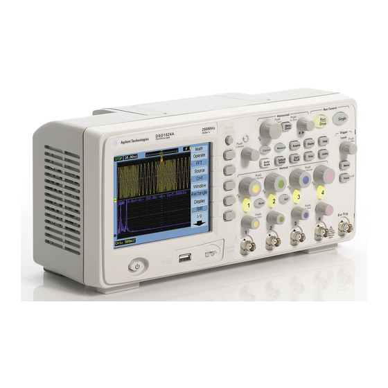
Keysight 1000A Series Oscilloscopes—At a Glance The Keysight 1000A Series oscilloscopes are low-cost portable digital storage oscilloscopes (DSOs) that deliver these powerful features: • Two and four-channel, 60 MHz, 100 MHz, and 200 MHz bandwidth models. • Bright 5.7 inch QVGA (320 x 240) TFT color LCD display and small footprint (to save bench space). -
Page 4: In This Book
In This Book This guide shows how to use the Keysight 1000A Series oscilloscopes. Getting Started Describes the basic steps to take when first using the oscilloscope. Displaying Data Describes how to use the horizontal and vertical controls, channel settings, math waveforms, reference waveforms, and display settings. -
Page 5: Table Of Contents
Contents Keysight 1000A Series Oscilloscopes—At a Glance / 3 In This Book / 4 Figures / 13 Tables / 15 Getting Started Step 1. Inspect the package contents / 18 Step 2. Turn on the oscilloscope / 19 Step 3. Load the default oscilloscope setup / 20 Step 4. - Page 6 To display waveforms as vectors or dots / 56 To clear the display / 56 To set waveform persistence / 57 To adjust waveform intensity / 57 To display graded waveform intensity / 58 Keysight 1000A Series Oscilloscopes User’s Guide...
- Page 7 To force a trigger / 78 Choosing the Trigger Mode / 80 To set up edge triggers / 80 To set up pulse width triggers / 81 To set up video triggers / 82 Keysight 1000A Series Oscilloscopes User’s Guide...
- Page 8 Vamp (Amplitude Voltage = Vtop - Vbase) / 97 Vavg (Average Voltage) / 97 Vrms (Root-Mean-Square Voltage) / 97 Overshoot / 98 Preshoot / 98 Time Measurements / 99 Period / 99 Frequency / 100 Rise Time / 100 Keysight 1000A Series Oscilloscopes User’s Guide...
- Page 9 To edit folder/file names / 116 To delete folders / 117 To rename folders / 117 To delete files / 117 To recall files / 117 To rename files / 118 To display disk information / 118 Keysight 1000A Series Oscilloscopes User’s Guide...
- Page 10 To select the vertical scale reference level / 131 To select the USB device port function / 131 Running Self-Calibration / 132 Specifications and Characteristics Environmental Conditions / 136 Overvoltage Category / 136 Pollution Degree / 136 Pollution Degree Definitions / 136 Keysight 1000A Series Oscilloscopes User’s Guide...
- Page 11 Measurement Category / 137 Measurement Category Definitions / 137 Maximum Input Voltages / 137 / 137 / 137 Specifications / 138 Characteristics / 139 Safety Notices Warnings / 147 Safety Symbols / 148 Index Keysight 1000A Series Oscilloscopes User’s Guide...
- Page 12 Keysight 1000A Series Oscilloscopes User’s Guide...
-
Page 13: Figures
Figure 23. FFT Waveform / 53 Figure 24. [Display] Key / 56 Figure 25. Alaising / 63 Figure 26. Theoretical Brick-Wall Frequency Response / 64 Figure 27. Sample Rate and Oscilloscope Bandwidth / 65 Keysight 1000A Series Oscilloscopes User’s Guide... - Page 14 Figure 51. [Print] Key Location / 120 Figure 52. [Utility] Key / 123 Figure 53. Mask Test Display / 127 Figure 54. Mask Test Mask Setting / 129 Figure 55. Calibration Screen / 133 Keysight 1000A Series Oscilloscopes User’s Guide...
-
Page 15: Tables
Tables Table 1. Keysight 1000A Series Oscilloscope Models / 3 Table 2. Auto-Scale Default Settings / 23 Table 3. Front Panel Controls / 26 Table 4. FFT Window Characteristics / 52 Table 5. Specifications / 138 Table 6. Acquisition System Characteristics / 139 Table 7. - Page 16 Tables Keysight 1000A Series Oscilloscopes User’s Guide...
-
Page 17: Getting Started
Keysight 1000A Series Oscilloscopes User’s Guide 1 Getting Started Step 1. Inspect the package contents / 18 Step 2. Turn on the oscilloscope / 19 Step 3. Load the default oscilloscope setup / 20 Step 4. Input a waveform / 21 Step 5. -
Page 18: Step 1. Inspect The Package Contents
Keysight Technologies sales office. • If the shipping container is damaged, or the cushioning materials show signs of stress, notify the carrier; then, contact your nearest Keysight Technologies sales office. Keep the shipping materials for the carrier’s inspection. -
Page 19: Step 2. Turn On The Oscilloscope
Use a power source that delivers the required power (see Table 16 page 145). To avoid electric shock, be sure the oscilloscope is properly grounded. WARNING 2 Turn on the oscilloscope. Figure 1 Power Switch Keysight 1000A Series Oscilloscopes User’s Guide... -
Page 20: Step 3. Load The Default Oscilloscope Setup
2 When the Default menu appears, press [Menu On/Off] to turn off the menu. (The Undo softkey in the Default menu lets you cancel the default setup and go back to the previous setup.) Keysight 1000A Series Oscilloscopes User’s Guide... -
Page 21: Step 4. Input A Waveform
Use one of the supplied passive probes to input the Probe Comp signal from the front panel of the oscilloscope. To avoid damage to the oscilloscope, make sure that the input voltage at the BNC CAUTION connector does not exceed the maximum voltage (300 Vrms maximum). Keysight 1000A Series Oscilloscopes User’s Guide... -
Page 22: Step 5. Use Auto-Scale
The trigger source selected is the highest-numbered channel that has a waveform applied. (The Undo softkey in the AUTO menu lets you cancel the auto-scale and go back to the previous setup.) Keysight 1000A Series Oscilloscopes User’s Guide... -
Page 23: Table 2. Auto-Scale Default Settings
Adjusted Volts/Div Coarse Bandwidth limit Waveform invert Horizontal position Center Horizontal "S/div" Adjusted Trigger type Edge Trigger source Measure the channel with input waveform automatically. Trigger coupling Trigger voltage Midpoint setting Trigger sweep Auto Keysight 1000A Series Oscilloscopes User’s Guide... -
Page 24: Step 6. Compensate Probes
4 If waveform does not appear like the Correctly Compensated waveform shown Figure 4, then use a nonmetallic tool to adjust the low frequency compensation adjustment on the probe for the flattest square wave possible. Keysight 1000A Series Oscilloscopes User’s Guide... -
Page 25: Step 7. Become Familiar With The Front Panel Controls
Push Softkeys for Vernier for Vernier Menu Local Local Force Math Push Push to Zero to Zero All Inputs 1MW_15pF 400Vrms CATI Setup controls Menu controls Vertical controls Trigger controls Figure 5 Front Panel Keysight 1000A Series Oscilloscopes User’s Guide... -
Page 26: Front Panel Overlays For Different Languages
3 When the overlay is against the front panel, insert the tabs on the right side of the overlay into the slots on the front panel. 4 Let the overlay flatten out. It should remain secure on the front panel. Keysight 1000A Series Oscilloscopes User’s Guide... -
Page 27: Using The Oscilloscope Softkey Menus
When one of the oscilloscope front panel keys turns on a menu, you can use the five softkeys to choose items from the menu. Some common menu item choices are: Accesses the next page of items in the menu. Accesses the previous page of items in the menu. Keysight 1000A Series Oscilloscopes User’s Guide... - Page 28 The [Menu On/Off] front panel key turns off the menu or turns on the last accessed menu on again. The Menu Display item in the Display menu lets you select the amount of time menus are displayed (see “To change the menu display time" page 58). Keysight 1000A Series Oscilloscopes User’s Guide...
-
Page 29: Step 8. Become Familiar With The Oscilloscope Display
Acquisition Status Trigger, rising edge, channel 1, Timebase 154 mV Status, 500 us per division Waveform Channel 1 Reference Channel 1 Status, DC coupling, 50 mV per division Figure 7 Oscilloscope Display Keysight 1000A Series Oscilloscopes User’s Guide... -
Page 30: Step 9. Use The Run Control Keys
• When the [Run/Stop] key is red, data acquisition is stopped. To start acquiring data, press [Run/Stop]. • To capture and display a single acquisition (whether the oscilloscope is running or stopped), press [Single]. After capturing and displaying a single acquisition, the [Run/Stop] key is red. Keysight 1000A Series Oscilloscopes User’s Guide... -
Page 31: Step 10. Access The Built-In Help
2 Press the front panel key, softkey, or pushable knob on which you would like quick help information. The built-in help is available in 11 different languages (see “Setting the Language (Menu and Help)" on page 125). Keysight 1000A Series Oscilloscopes User’s Guide... -
Page 32: Securing The Oscilloscope
Getting Started Securing the Oscilloscope To secure a 1000A Series oscilloscope to its location, you can use a Kensington lock or the security loop. Security loop Hole for Kensington lock Figure 10 Securing the Instrument Keysight 1000A Series Oscilloscopes User’s Guide... -
Page 33: Displaying Data
Keysight 1000A Series Oscilloscopes User’s Guide 2 Displaying Data Using the Horizontal Controls / 34 Using the Vertical Controls / 41 Using Math Function Waveforms / 50 Using Reference Waveforms / 54 Changing the Display Settings / 56 This chapter describes how to use the horizontal and vertical controls, channel... -
Page 34: Using The Horizontal Controls
(delayed) time base, change the time base mode, and display the sample rate. Menu Zoom Scale knob Position knob Figure 11 Horizontal Controls Figure 12 shows the screen icon descriptions and control indicators. Keysight 1000A Series Oscilloscopes User’s Guide... -
Page 35: To Adjust The Horizontal Scale
(time/div) setting (and the oscilloscope’s sample rate — see “Memory Depth and Sample Rate" on page 68). The time/div setting changes in a 1-2-5 step sequence. The time/div setting is also known as the sweep speed. Keysight 1000A Series Oscilloscopes User’s Guide... -
Page 36: To Adjust The Horizontal Position
The position knob adjusts the horizontal position of all channels, math functions, and reference waveforms. • Push the horizontal position knob to “zero” the trigger point (in other words, move it to the center of the screen). Keysight 1000A Series Oscilloscopes User’s Guide... -
Page 37: To Display The Zoomed Time Base
The horizontal position knob moves the area of magnification forward and backward on the original waveform. • The bottom half of the display shows the magnified data in the zoomed time base. Zoomed window Zoomed window view Figure 13 Zoomed Time Base Window Keysight 1000A Series Oscilloscopes User’s Guide... -
Page 38: To Change The Horizontal Time Base (Y-T, X-Y, Or Roll)
The oscilloscope uses the untriggered sample acquisition mode and waveform data is displayed as dots. The sampling rate can vary from 4 kSa/s to 100 MSa/s, and the default sampling rate is 1 MSa/s. Keysight 1000A Series Oscilloscopes User’s Guide... -
Page 39: Figure 14 X-Y Display Format Showing Out-Of-Phase Waveforms
Displaying Data Figure 14 X-Y Display Format Showing Out-of-Phase Waveforms Keysight 1000A Series Oscilloscopes User’s Guide... -
Page 40: To View The Sample Rate
1 Press [Menu/Zoom]. 2 In the Horizontal menu, the Sa Rate menu item displays the sample rate used for the current horizontal scale setting. See Also “Memory Depth and Sample Rate" on page 68. Keysight 1000A Series Oscilloscopes User’s Guide... -
Page 41: Using The Vertical Controls
• If the waveform is on and its menu is not displayed, its menu will be displayed. • If the waveform is on and its menu is displayed, the waveform is turned off and its menu goes away. To adjust the vertical scale When an input channel waveform is on: Keysight 1000A Series Oscilloscopes User’s Guide... -
Page 42: To Adjust The Vertical Position
Notice that, as you adjust the vertical position, a message showing the position of the ground reference relative to the center of the screen is temporarily displayed in the lower left-hand corner of the screen. Keysight 1000A Series Oscilloscopes User’s Guide... -
Page 43: To Specify Channel Coupling
This lets you use greater sensitivity (amplitude/div settings) to display the AC component of the waveform. The waveform is disconnected from the oscilloscope input. DC Coupling DC Coupling Status Figure 16 DC Coupling Control Keysight 1000A Series Oscilloscopes User’s Guide... -
Page 44: To Specify A Bandwidth Limit
1 If the channel’s menu is not currently displayed, press the channel key ([1], [2], [3], or [4]). 2 In the Channel menu, press BW Limit to toggle the bandwidth limit setting “ON” and “OFF”. Keysight 1000A Series Oscilloscopes User’s Guide... -
Page 45: Figure 18 Bw Limit Control Off
Displaying Data Bandwidth limit OFF Figure 18 BW Limit Control OFF 20 MHz Bandwidth Bandwidth ON Status Figure 19 BW Limit Control ON Keysight 1000A Series Oscilloscopes User’s Guide... -
Page 46: To Specify The Probe Attenuation
2 In the Channel menu, press Digital Fil ter. 3 In the Filter menu, press Fil ter Type, and continue pressing the Fil ter Type softkey or turn the entry knob to select between: LPF (Low Pass Filter). HPF (High Pass Filter). Keysight 1000A Series Oscilloscopes User’s Guide... -
Page 47: To Change The Volts/Div Control Sensitivity
You can also toggle between coarse and fine settings by pushing the vertical scale knob (see “To adjust the vertical scale" on page 41). To invert a waveform You can invert a waveform with respect to the ground level. Keysight 1000A Series Oscilloscopes User’s Guide... -
Page 48: Figure 20 Waveform Before Inversion
1 If the channel’s menu is not currently displayed, press the channel key ([1], [2], [3], or [4]). 2 In the Channel menu, press Invert to toggle between “ON” and “OFF”. Figure 20 Figure 21 show the changes before and after inversion. Figure 20 Waveform Before Inversion Keysight 1000A Series Oscilloscopes User’s Guide... -
Page 49: To Specify The Channel Units
[3], or [4]). 2 In the Channel menu, press Unit. 3 Continue pressing the Unit softkey or turn the entry knob to select between: Volts, used with voltage probes. Amperes, used with current probes. Watts. Unknown. Keysight 1000A Series Oscilloscopes User’s Guide... -
Page 50: Using Math Function Waveforms
The math scale setting is shown at the bottom of the display. Math Scale Figure 22 Math Scale Setting Value To add, subtract, or multiply waveforms 1 Press [Math]. 2 In the Math menu, press Operate. Keysight 1000A Series Oscilloscopes User’s Guide... -
Page 51: To Display The Frequency Domain Using Fft
There are four FFT windows. Each window has trade-offs between frequency resolution and amplitude accuracy. What you want to measure and your source waveform characteristics help determine which window to use. Use the guidelines in Table 4 to select the best window. Keysight 1000A Series Oscilloscopes User’s Guide... -
Page 52: Table 4. Fft Window Characteristics
10 Use the horizontal position knob to adjust the frequency per division. The frequency scale is displayed on the screen. Use this to display the frequencies associated with the peaks in the FFT waveform. Keysight 1000A Series Oscilloscopes User’s Guide... -
Page 53: Figure 23 Fft Waveform
This frequency is half of the sample rate. Frequencies above the Nyquist frequency will be under sampled, which causes aliasing. The Nyquist frequency is also called the folding frequency because aliased frequency components fold back from that frequency when viewing the frequency domain. Keysight 1000A Series Oscilloscopes User’s Guide... -
Page 54: Using Reference Waveforms
2 If exporting a waveform, in the REF menu, press Source, and continue pressing the softkey or turn the entry knob to select the waveform you want to export. 3 Presh Location to choose “External”. 4 Press Save or Import. Keysight 1000A Series Oscilloscopes User’s Guide... -
Page 55: To Return The Reference Waveform To Its Default Scale
To load the selected waveform (.wfm file), press Import. To return the reference waveform to its default scale 1 Press [REF]. 2 In the REF menu, press Reset. The scale and position of the waveform as originally saved are restored. Keysight 1000A Series Oscilloscopes User’s Guide... -
Page 56: Changing The Display Settings
The digital interpolation is suitable for real time sampling and is most effective at 20 ns or faster horizontal scale settings. Dots The sample points are displayed. To clear the display 1 Press [Display]. 2 In the Display menu, press Clear. Keysight 1000A Series Oscilloscopes User’s Guide... -
Page 57: To Set Waveform Persistence
Sample points remain displayed until the display is cleared or persistence is set to “OFF”. To adjust waveform intensity 1 Press [Display]. 2 In the Display menu, press Intensity and turn the entry knob to adjust the waveform intensity. Keysight 1000A Series Oscilloscopes User’s Guide... -
Page 58: To Display Graded Waveform Intensity
2 In the Display menu, press Menu Display, and continue pressing the softkey or turn the entry knob to select “1 S”, “2 S”, “5 S”, “10 S”, “20 S”, or “Infinite” menu display time. Keysight 1000A Series Oscilloscopes User’s Guide... -
Page 59: To Adjust The Grid Brightness
To invert screen colors 1 Press [Display]. 2 In the Display menu, press Screen to toggle the screen between “Normal” or “Inverted” colors. Inverted screen colors are sometimes useful when printing or saving screens. Keysight 1000A Series Oscilloscopes User’s Guide... -
Page 60: To Select Screen Persistence
1 Press [Display]. 2 In the Display menu, press Screen Persist to toggle between: When acquisitions are stopped, the screen may show data from many acquistions. When acquisitions are stopped, the last acquisition is displayed. Keysight 1000A Series Oscilloscopes User’s Guide... -
Page 61: Capturing Data
Keysight 1000A Series Oscilloscopes User’s Guide 3 Capturing Data Overview of Sampling / 62 Choosing the Acquisition Mode / 69 Recording/Playing-back Waveforms / 74 Adjusting the Trigger Level / 78 Choosing the Trigger Mode / 80 Setting Other Trigger Parameters / 87... -
Page 62: Overview Of Sampling
/2 = Nyquist frequency (f ) = folding frequency Aliasing Aliasing occurs when signals are under-sampled (f < 2f ). Aliasing is the signal distortion caused by low frequencies falsely reconstructed from an insufficient number of sample points. Keysight 1000A Series Oscilloscopes User’s Guide... -
Page 63: Oscilloscope Bandwidth And Sample Rate
At the oscilloscope bandwidth, sampling theory says the required sample rate is = 2f . However, the theory assumes there are no frequency components above in this case) and it requires a system with an ideal brick-wall frequency response. Keysight 1000A Series Oscilloscopes User’s Guide... -
Page 64: Figure 26 Theoretical Brick-Wall Frequency Response
(square waves are made up of sine waves at the fundamental frequency and an infinite number of odd harmonics), and typically, for 1 Ghz bandwidths and below, oscilloscopes have a Gaussian frequency response. Keysight 1000A Series Oscilloscopes User’s Guide... -
Page 65: Oscilloscope Rise Time
10% to 90% criterion. An oscilloscope’s rise time is not the fastest edge speed that the oscilloscope can accurately measure. It is the fastest edge speed the oscilloscope can possibly produce. Keysight 1000A Series Oscilloscopes User’s Guide... -
Page 66: Oscilloscope Bandwidth Required
= 1.0 x f knee = 1.3 x f knee = 1.9 x f knee See Also Choosing an Oscilloscope with the Right Bandwidth for your Application, Keysight Application Note 1588 (http://literature.cdn.Keysight.com/litweb/pdf/5989-5733EN.pdf) Keysight 1000A Series Oscilloscopes User’s Guide... -
Page 67: Real-Time Sampling
See Figure N = Waveform Sample is From Trigger Time Figure 28 Real-Time Sampling Mode The 1000A Series oscilloscopes provide real-time sampling rates up to 2 GSa/s. Keysight 1000A Series Oscilloscopes User’s Guide... -
Page 68: Memory Depth And Sample Rate
10 kSa/s. The actual sample rate, is displayed in the horizontal Horizontal menu (see “To view the sample rate" on page 40). The oscilloscope achieves the actual sample rate by throwing away (decimating) unneeded samples. Keysight 1000A Series Oscilloscopes User’s Guide... -
Page 69: Choosing The Acquisition Mode
3 Continue pressing the Acquisition softkey or turn the entry knob to select “Normal”. To select the Average acquisition mode In the Average acquisition mode, acquisitions are made, and the running average over the specified number of acquisitions is displayed. Keysight 1000A Series Oscilloscopes User’s Guide... -
Page 70: Figure 30 Noisy Waveform Without Averaging
Capturing Data Use the Average acquisition mode to remove random noise from the waveform and to improve measurement accuracy. Figure 30 Noisy Waveform Without Averaging Figure 31 Noisy Waveform With Averaging Keysight 1000A Series Oscilloscopes User’s Guide... -
Page 71: To Select The Peak Detect Acquisition Mode
This way, you can capture narrow excursions on a signal at longer horizontal time/div settings. Keysight 1000A Series Oscilloscopes User’s Guide... -
Page 72: Figure 32 Peak Detect Waveform
Peak Detect acquisition mode to avoid waveform aliasing. To select the Peak Detect acquisition mode: 1 Press [Acquire]. 2 In the Acquire menu, press Acquisition. 3 Continue pressing the Acquisition softkey or turn the entry knob to select “Peak Detect”. Keysight 1000A Series Oscilloscopes User’s Guide... -
Page 73: To Turn Off/On Sine(X)/X Interpolation
The effects of sine(x)/x interpolation are only noticeable when the horizontal scale is set to 20 ns or faster. 1 Press [Acquire]. 2 In the Acquire menu, press Sinx/x to turn sine(x)/x interpolation “OFF” or “ON”. Keysight 1000A Series Oscilloscopes User’s Guide... -
Page 74: Recording/Playing-Back Waveforms
1 to 800. To start/stop recording 1 In the Sequence menu ([Acquire] > Sequence > Mode=Record), press Operate to start or stop recording. Appears on the menu when not recording; press Operate to start recording. Keysight 1000A Series Oscilloscopes User’s Guide... -
Page 75: To Play-Back Waveforms
Appears on the menu when playing-back; press Operate to stop playing-back. To select continuous or one-time play-back 1 In the Sequence menu ([Acquire] > Sequence > Mode=Play back), press Play Mode to toggle between: Continuous play-back. One-time play-back. Keysight 1000A Series Oscilloscopes User’s Guide... -
Page 76: To Store Recorded Waveforms
1 In the Sequence menu ([Acquire] > Sequence > Mode=Storage), press Start Frame. 2 Turn the entry knob to select a number from l to 800. To select the end frame 1 In the Sequence menu ([Acquire] > Sequence > Mode=Storage), press End Frame. Keysight 1000A Series Oscilloscopes User’s Guide... - Page 77 2 In the Sequence menu ([Acquire] > Sequence > Mode=Storage), press Imp./Exp.. 3 Use the Disk Manager to select the file and import or export the waveform recording. See “Using the Disk Manager" on page 114. Keysight 1000A Series Oscilloscopes User’s Guide...
-
Page 78: Adjusting The Trigger Level
1 Press [Force]. Forcing a trigger is useful, for example, when you want to display the DC voltage of a level signal. The [Force] key has no effect if the acquisition is already stopped. Keysight 1000A Series Oscilloscopes User’s Guide... - Page 79 When the oscilloscope’s front panel is locked by a remote program (shown by a red “Rmt” on the upper-right part of the display), pressing the [Force] key returns the front panel to Local control. Keysight 1000A Series Oscilloscopes User’s Guide...
-
Page 80: Choosing The Trigger Mode
Mode again. 5 Press Source and continue pressing the softkey or turn the entry knob to select the waveform to trigger on: CH1 - CH4 The oscilloscope input channel. The external trigger input. Keysight 1000A Series Oscilloscopes User’s Guide... -
Page 81: To Set Up Pulse Width Triggers
The oscilloscope input channel. The external trigger input. EXT/5 The (5:1) attenuated external trigger input. 6 Press When and continue pressing the softkey or turn the entry knob to select the type of pulse to trigger on: Keysight 1000A Series Oscilloscopes User’s Guide... -
Page 82: To Set Up Video Triggers
Normal Polarity Sync triggers always occur on negative-going horizontal sync pulses. If the NOTE video waveform has positive-going horizontal sync pulses, use the Inverted Polarity selection. 6 Press Sync and continue pressing the softkey or turn the entry knob to select what to trigger on: Keysight 1000A Series Oscilloscopes User’s Guide... -
Page 83: Figure 34 Line Synchronization
Even Field Trigger on an even field. 7 Press Standard to toggle between: NTSC Trigger on an NTSC video waveform. PAL/ SECAM Trigger on a PAL or SECAM video waveform. Figure 34 Line Synchronization Keysight 1000A Series Oscilloscopes User’s Guide... -
Page 84: To Set Up Pattern Triggers
The oscilloscope input channel. The external trigger input. EXT/5 The (5:1) attenuated external trigger input. 6 Press Code and continue pressing the softkey or turn the entry knob to select the value for the selected channel: Keysight 1000A Series Oscilloscopes User’s Guide... -
Page 85: To Set Up Alternate Triggers
At this point, the remaining items in the Trigger menu let you set up independent triggers for the selected channel. For each source, you can set up edge, pulse width, or video triggering. You can also specify other trigger setup options, except trigger sweep. Keysight 1000A Series Oscilloscopes User’s Guide... -
Page 86: Figure 36 Alternate Triggers
Capturing Data Figure 36 Alternate Triggers Keysight 1000A Series Oscilloscopes User’s Guide... -
Page 87: Setting Other Trigger Parameters
To set the trigger coupling: 1 Press [Menu]. 2 In the Trigger menu, press Set Up. 3 In the Set Up menu, press Coupling. Keysight 1000A Series Oscilloscopes User’s Guide... -
Page 88: To Set The Trigger High-Frequency Reject Coupling
To set the trigger high-frequency reject coupling: 1 Press [Menu]. 2 In the Trigger menu, press Set Up. 3 In the Set Up menu, press HF Reject to toggle between “ON” and “OFF”. Keysight 1000A Series Oscilloscopes User’s Guide... -
Page 89: To Change The Trigger Sensitivity
To change the trigger sensitivity Trigger sensitivity specifies the vertical change that must occur in order for a trigger to be recognized. In the 1000A Series oscilloscopes, you can adjust the trigger sensitivity. For example, to reduce the influence of noise, you can lower the trigger sensitivity (by increasing the vertical change required to trigger). -
Page 90: To Specify A Trigger Holdoff
To reset the trigger holdoff 1 In the Set Up menu, select the Holdoff Reset menu item to return the trigger holdoff setting to the 100 ns minimum value. Keysight 1000A Series Oscilloscopes User’s Guide... -
Page 91: Using The External Trigger Input
Capturing Data Using the External Trigger Input You can trigger on external inputs by selecting “EXT” or “EXT/5” (5:1 attenuated) as the trigger source in all trigger modes except Alternate. Keysight 1000A Series Oscilloscopes User’s Guide... - Page 92 Capturing Data Keysight 1000A Series Oscilloscopes User’s Guide...
-
Page 93: Making Measurements
Keysight 1000A Series Oscilloscopes User’s Guide 4 Making Measurements Displaying Automatic Measurements / 94 Voltage Measurements / 96 Time Measurements / 99 Counter (Frequency) / 104 Making Cursor Measurements / 105 This chapter shows how to make automatic voltage measurements, automatic... -
Page 94: Displaying Automatic Measurements
Vol tage or Time again to add the measurement to the bottom of the display. If the measurement result is displayed as "*****", the measurement cannot be performed with the current oscilloscope settings. Keysight 1000A Series Oscilloscopes User’s Guide... -
Page 95: To Clear Automatic Measurements From The Display
To select channels for delay/phase measurements 1 Press [Measure]. 2 In the Measure menu, press Delay/Phase. 3 In the Delay/Phase menu, press DelayA, DelayB, PhaseA, or PhaseB to select the input channel for the respective measurement. Keysight 1000A Series Oscilloscopes User’s Guide... -
Page 96: Voltage Measurements
• Overshoot. • Preshoot. Overshoot Overshoot base Preshoot Figure 39 Voltage Measurement Points Vmax (Maximum Voltage) The maximum amplitude. The most positive peak voltage measured over the entire waveform. See Figure 39 on page 96. Keysight 1000A Series Oscilloscopes User’s Guide... -
Page 97: Vmin (Minimum Voltage)
Vavg (Average Voltage) The arithmetic mean over the entire waveform. Vrms (Root-Mean-Square Voltage) The true root-mean-square voltage over the entire waveform. --------------- - Where: = value at i point. n = number of points. Keysight 1000A Series Oscilloscopes User’s Guide... -
Page 98: Overshoot
Making Measurements Overshoot Defined as (Vmax-Vtop)/Vamp, useful for square and pulse waveforms. See Figure 39 on page 96. Preshoot Defined as (Vmin-Vbase)/Vamp, useful for square and pulse waveforms. See Figure 39 on page 96. Keysight 1000A Series Oscilloscopes User’s Guide... -
Page 99: Time Measurements
• Delay A-B, rising edges. • Delay A-B, falling edges. • Phase A-B, rising edges. • Phase A-B, falling edges. Period Measures the period of a waveform. Time origin line Base Period Figure 40 Period and Frequency Measurements Keysight 1000A Series Oscilloscopes User’s Guide... -
Page 100: Frequency
90% (upper) 50% (middle) 10% (lower) Vbase Rising Falling edge edge Figure 41 Rise Time and Fall Time Measurements Fall Time Measures the fall time of a waveform. See Figure 41 on page 100. Keysight 1000A Series Oscilloscopes User’s Guide... -
Page 101: Positive Pulse Width
Measures the negative pulse width of a waveform. See Figure 42 on page 101. Positive Duty Cycle Measures the positive duty cycle of a waveform. Negative Duty Cycle Measures the negative duty cycle of a waveform. Keysight 1000A Series Oscilloscopes User’s Guide... -
Page 102: Delay Between Rising Edges
Channel 2 Delay from channel 1 to channel 2 falling edge Figure 43 Delay Measurements Delay Between Falling Edges Measures the delay between two waveforms using the falling edges. See Figure 43 on page 102. Keysight 1000A Series Oscilloscopes User’s Guide... -
Page 103: Phase Between Rising Edges
Channel 2 Phase from channel 1 to channel 2 rising edge Figure 44 Phase Measurements Phase Between Falling Edges Measures the phase between two waveforms using the falling edges. See Figure 44 on page 103. Keysight 1000A Series Oscilloscopes User’s Guide... -
Page 104: Counter (Frequency)
Making Measurements Counter (Frequency) The 1000A Series oscilloscopes have an integrated 6-digit hardware frequency counter. The counter operates on the currently selected trigger source and can measure frequencies from 5 Hz to the bandwidth of the oscilloscope. The counter uses the trigger comparator to count the number of cycles within a period of time (known as the gate time), so the trigger level must be set correctly. -
Page 105: Making Cursor Measurements
To use manually adjustable cursors You can set up two parallel, manually adjustable cursors to make amplitude (vertical) or time (horizontal) measurements on a selected waveform. 1 Press [Cursors]. 2 In the Cursors menu, press Mode. Keysight 1000A Series Oscilloscopes User’s Guide... -
Page 106: To Use Tracking Cross-Hair Cursors
“Track”. 4 Press Cursor A, and continue pressing the softkey or turn the entry knob to select the channel on which to make the measurement (or “None” to turn off the cursor). Keysight 1000A Series Oscilloscopes User’s Guide... -
Page 107: To Display Cursors For Automatic Measurements
In the “Auto” cursors mode: • Cursors appear for the most recently displayed automatic measurement (see “To display an automatic measurement" on page 94). • No cursors are displayed if there are no automatic measurements. Keysight 1000A Series Oscilloscopes User’s Guide... - Page 108 Making Measurements Keysight 1000A Series Oscilloscopes User’s Guide...
-
Page 109: Saving, Recalling, And Printing Data
Keysight 1000A Series Oscilloscopes User’s Guide 5 Saving, Recalling, and Printing Data Saving and Recalling Data / 110 Using the Disk Manager / 114 Printing Screens / 119 This chapter describes how to save, recall, and print data. The oscilloscope has internal, nonvolatile memory locations for saving and recalling waveforms and setups. -
Page 110: Saving And Recalling Data
You can also save/recall waveforms and setups to an external USB drive when it is connected to a rectangular USB host port. 1 Press [Save/Recall]. 2 In the Storage menu, press Storage. 3 Continue pressing the Storage softkey or turn the entry knob to select “Waveform”. Keysight 1000A Series Oscilloscopes User’s Guide... -
Page 111: To Save And Recall Oscilloscope Setups
You can also save/recall setups to an external USB drive when it is connected to the front panel USB host port. 1 Press [Save/Recall]. 2 In the Storage menu, press Storage. 3 Continue pressing the Storage softkey or turn the entry knob to select “Setups”. Keysight 1000A Series Oscilloscopes User’s Guide... -
Page 112: To Save Screens To Bmp Or Png Format Files
8-Bitmap 8-bit BMP format. 24-Bitmap 24-bit BMP format. Portable Network Graphics format. 4 To specify whether oscilloscope parameters be saved along with the screen, press Para Save to toggle between on and off. Keysight 1000A Series Oscilloscopes User’s Guide... -
Page 113: To Save Data To Csv Format Files
7 Use the disk manager dialog to navigate to the folder where you want to save the file (see “To navigate the directory hierarchy" on page 115). 8 In the External menu, press New File, enter the filename (see “To edit folder/file names" on page 116), and press Save. Keysight 1000A Series Oscilloscopes User’s Guide... -
Page 114: Using The Disk Manager
Disk Manager to select and name files and folders. To access the Disk Mana. menu: 1 Press [Save/Recall]. 2 In the Storage menu, press Disk Mana.. The Disk Manager screen appears. It looks similar to: Figure 48 Disk Manager Keysight 1000A Series Oscilloscopes User’s Guide... -
Page 115: To Switch Between Files, Path, And Directory Panes
1 In the Disk Mana. menu ([Save/Recall] > Disk Mana.), press New Folder. 2 Use the folder/file naming dialog to enter the folder name. See “To edit folder/file names" on page 116. 3 In the New Folder menu, press Save. Keysight 1000A Series Oscilloscopes User’s Guide... -
Page 116: To Edit Folder/File Names
On “Aa”, change from upper to lower case characters on the keypad. • On “En”, change from single-byte to multi-byte character entry fields. • Select the menu item to delete a character from the name. Keysight 1000A Series Oscilloscopes User’s Guide... -
Page 117: To Delete Folders
To recall files In the files pane (see “To switch between files, path, and directory panes" page 115): 1 Turn the entry knob to select the file. 2 Press Recall to load the selected file. Keysight 1000A Series Oscilloscopes User’s Guide... -
Page 118: To Rename Files
3 Use the folder/file naming dialog to edit the file name. See “To edit folder/file names" on page 116. 4 In the Rename menu, press Ok. To display disk information 1 In the Disk Mana. menu ([Save/Recall] > Disk Mana.), press Disk info. Keysight 1000A Series Oscilloscopes User’s Guide... -
Page 119: Printing Screens
You can print oscilloscope display screens to: • A PictBridge compliant printer connected to the (square) USB device port on the oscilloscope’s back panel. USB Device Port USB Host Port Figure 50 USB Ports on Back Panel Keysight 1000A Series Oscilloscopes User’s Guide... -
Page 120: To Choose A Pictbridge Printer
PictBridge compliant printing and remote programming features cannot be used at the same time. For more information on remote programming, see the Keysight 1000A Series Oscilloscopes Programmer’s Guide. If there are problems when connecting the USB device port to a PictBridge compliant printer or remote computer, see “To select the USB device port function"... -
Page 121: To Print With Inverted Screen Colors
Color When this option is selected, the traces are printed in color. To copy a screen to the printer 1 Press [Print]. 2 In the Print menu, press the Print softkey. Keysight 1000A Series Oscilloscopes User’s Guide... - Page 122 Saving, Recalling, and Printing Data Keysight 1000A Series Oscilloscopes User’s Guide...
-
Page 123: Figure 52 [Utility] Key
Keysight 1000A Series Oscilloscopes User’s Guide 6 Oscilloscope Utility Settings Displaying System Information / 124 Turning Sound ON or OFF / 124 Setting and Displaying the Date and Time / 124 Setting the Language (Menu and Help) / 125 Performing Mask Tests / 126... -
Page 124: Oscilloscope Utility Settings
Appears on the menu when sound is on; press Sound to stop the test Setting and Displaying the Date and Time To set and display the oscilloscope’s date and time: 1 Press [Utility]. 2 In the Utilities menu, press Date/Time. 3 In the Date/time menu, press: Keysight 1000A Series Oscilloscopes User’s Guide... -
Page 125: Setting The Language (Menu And Help)
• Simplified Chinese. • Traditional Chinese. • Korean. • Japanese. • English. • German. • French. • Portuguese. • Spanish. • Italian. • Russian. If quick help is unavailable in a particular language, English is displayed. Keysight 1000A Series Oscilloscopes User’s Guide... -
Page 126: Performing Mask Tests
To select the source channel for mask tests 1 In the Mask Test menu ([Utility] > Mask Test), press Source. 2 Continue pressing the Source softkey or turn the entry knob to select the desired input channel. Keysight 1000A Series Oscilloscopes User’s Guide... -
Page 127: To Run/Stop A Mask Test
The message display shows the failed, passed, and total number of waveforms. Figure 53 Mask Test Display To set the mask test output condition 1 In the Mask Test menu ([Utility] > Mask Test), press Output. Keysight 1000A Series Oscilloscopes User’s Guide... -
Page 128: To Stop A Mask Test On The Output Condition
USB drive. To access the Mask menu: 1 Press [Utility]. 2 In the Utilities menu, press Mask Test. 3 In the Mask Test menu, press MaskSetting. Keysight 1000A Series Oscilloscopes User’s Guide... -
Page 129: Figure 54 Mask Test Mask Setting
The margin can be set from 0.04 div to 4.00 div. To create a mask using the failure margin settings 1 In the Mask menu ([Utility] > Mask Test > MaskSetting), press Create Mask. Keysight 1000A Series Oscilloscopes User’s Guide... - Page 130 When importing a mask while the Location is Internal or when importing or recalling a mask NOTE while the Location is External, the mask is imported or recalled to internal memory. To activate the mask, you must set the Location to Internal, then Recall from internal memory. Keysight 1000A Series Oscilloscopes User’s Guide...
-
Page 131: Setting Preferences
Vertical scale changes take place about the center of the display. See Also “To adjust the vertical scale" on page 41. To select the USB device port function The (square) USB device port on the oscilloscope’s back panel can be used for: Keysight 1000A Series Oscilloscopes User’s Guide... -
Page 132: Running Self-Calibration
Before performing the automatic calibration, let the oscilloscope warm-up at least 30 NOTE minutes. To run the oscilloscope’s self-calibration: 1 Press [Utility]. 2 In the Utilities menu, press Sel f-Cal. 3 Follow the instructions on the Calibration screen. Keysight 1000A Series Oscilloscopes User’s Guide... -
Page 133: Figure 55 Calibration Screen
Oscilloscope Utility Settings Figure 55 Calibration Screen Keysight 1000A Series Oscilloscopes User’s Guide... - Page 134 Oscilloscope Utility Settings Keysight 1000A Series Oscilloscopes User’s Guide...
- Page 135 Keysight 1000A Series Oscilloscopes User’s Guide 7 Specifications and Characteristics Environmental Conditions / 136 Measurement Category / 137 Specifications / 138 Characteristics / 139 This chapter describes the 1000A Series oscilloscopes’ specifications and characteristics.
-
Page 136: Specifications And Characteristics
This product is intended to be powered by MAINS that comply to Overvoltage Category II, which is typical of cord-and-plug connected equipment. Pollution Degree The 1000A Series oscilloscope may be operated in environments of Pollution Degree 2 (or Pollution Degree 1). Pollution Degree Definitions Pollution Degree 1: No pollution or only dry, non-conductive pollution occurs. -
Page 137: Measurement Category
Specifications and Characteristics Measurement Category The 1000A Series oscilloscope are not intended to be used for measurements in Measurement Category II, III, or IV. Measurement Category Definitions The "Not rated for CAT II, III, IV" measurement category is for measurements performed on circuits not directly connected to MAINS. -
Page 138: Specifications
(DC coupling): bandwidth < 5 mV/div: 1 div from DC to 10 MHz, 1.5 div from 10 MHz to 20 MHz 20 MHz when vertical scale is set to < 5 mV (1X probe attenuation). Keysight 1000A Series Oscilloscopes User’s Guide... -
Page 139: Characteristics
20 MHz when vertical scale is set to < 5 mV (1X probe attenuation). Denotes warranted specifications, all others are typical. Specifications are valid after a 30-minute warm-up period and ±10° C from firmware calibration temperature. Keysight 1000A Series Oscilloscopes User’s Guide... - Page 140 20 MHz when vertical scale is set to < 5 mV (1X probe attenuation). Denotes warranted specifications, all others are typical. Specifications are valid after a 30-minute warm-up period and ±10° C from firmware calibration temperature. Keysight 1000A Series Oscilloscopes User’s Guide...
-
Page 141: Table 8. Horizontal System Characteristics
1-2-5 increments when off, 1% minor increments between major settings when on. Modes: Main, Zoom, Roll, XY Bandwidth: Max bandwidth Denotes warranted specifications, all others are typical. Specifications are valid after a 30-minute warm-up period and ±10° C from firmware calibration temperature Keysight 1000A Series Oscilloscopes User’s Guide... -
Page 142: Table 9. Trigger System Characteristics
5.7-inch (145 mm) diagonal color TFT LCD Display update rate: Up to 400 waveforms/s Resolution: QVGA 320 x 240 dots Backlight intensity 300 cd/m Persistence: Off, infinite Display types: Dots, vectors Real-time clock: Time and date (user adjustable) Keysight 1000A Series Oscilloscopes User’s Guide... -
Page 143: Table 11 Measurement Features
Name Typical Value Points: Fixed at 1024 points Source of FFT: Oscilloscope channels 1 or 2 (or 3 or 4 on DSO1xx4A only) Window: Rectangular, blackman, hanning, hamming Amplitude: Display in dBVrms and Vrms Keysight 1000A Series Oscilloscopes User’s Guide... -
Page 144: Table 13 Storage
Most FAT formatted <2 GB or FAT32 formatted <32 GB flash drives. Table 14 I/O Name Typical Value Standard ports: 1 USB device, two USB host ports Max transfer rate: USB 2.0 full-speed up to 12 Mb/sec Printer compatibility: PictBridge compatible printer Keysight 1000A Series Oscilloscopes User’s Guide... -
Page 145: Table 15 General Characteristics
Thread a security cable through the built-in security loop on the rear panel. Table 16 Power Requirements Name Typical Value Line rating: ~Line 60 W max 100-120 V/50/60/400 Hz, ±10% 100-240 V/50/60 Hz, ±10% Keysight 1000A Series Oscilloscopes User’s Guide... -
Page 146: Table 17 Environmental Characteristics
WARNING (not rated for CAT II, III, IV). No transient overvol tages allowed. The N2739A rack mount kit is available for placing a 1000A Series oscilloscope into Electronic Industries Association (EIA) standard 19-inch (487-mm) rack cabinets. Installation instructions are included in the kit. -
Page 147: Warnings
Keysight 1000A Series Oscilloscopes User’s Guide A Safety Notices Warnings / 147 Safety Symbols / 148 This apparatus has been designed and tested in accordance with IEC Publication 1010, Safety Requirements for Measuring Apparatus, and has been supplied in a safe condition. -
Page 148: Safety Symbols
Hazardous voltage symbol. Earth terminal symbol: Used to indicate a circuit common connected to grounded chassis. Keysight 1000A Series Oscilloscopes User’s Guide... - Page 149 FFT (Fast Fourier Transform) math function, 50, backlight, LCD, FFT resolution, band pass filter, dBVrms scale, FFT windows, band reject filter, DC channel coupling, field synchronization, 84, bandwidth limit, DC trigger coupling, file names, editing, Keysight 1000A Series Oscilloscopes User’s Guide...
- Page 150 40, loading, holdoff, trigger, mask, creating, overshoot measurement, horizontal controls, mask, loading, overvoltage category, horizontal failure margin (mask), mask, saving, Keysight 1000A Series Oscilloscopes User’s Guide...
- Page 151 SECAM standard, 82, self-calibration, under-sampled signals, random noise, sensitivity, trigger, units, channel, real-time sampling mode, sensitivity, Volts/Div control, unknown units, recalling data, serial number, untriggered sample acquisition record waveforms, setups, saving and loading, mode, Keysight 1000A Series Oscilloscopes User’s Guide...
- Page 152 Vpp (peak-to-peak voltage) measurement, Vrms (root-mean-square voltage) measurement, Vtop (top voltage) measurement, warnings, watt units, waveform intensity, waveform intensity, graded, waveform math, waveform persistence, waveforms, recording/playing-back, 3, waveforms, turning on or off, window, FFT, Keysight 1000A Series Oscilloscopes User’s Guide...
- Page 154 This information is subject to change without notice. © Keysight Technologies, Inc. 2008-2009, 2017 Printed in Malaysia Third Edition, August 2017 *54130-97016* 54130-97016 www.keysight.com...
Need help?
Do you have a question about the 1000A Series and is the answer not in the manual?
Questions and answers