Table of Contents
Advertisement
Advertisement
Table of Contents

Related Manuals for Keysight Technologies InfiniiVision 1000 X Series


Summary of Contents for Keysight Technologies InfiniiVision 1000 X Series
- Page 1 Keysight InfiniiVision 1000 X-Series Oscilloscopes User's Guide...
- Page 2 Technology License otherwise modify the Software. With respect Keysight Technologies, Inc. as governed by to any technical data as defined by FAR United States and international copyright The hardware and/or software described in 2.101, pursuant to FAR 12.211 and 27.404.2...
- Page 3 WARNING A WARNING notice denotes a hazard. It calls attention to an operating procedure, practice, or the like that, if not correctly performed or adhered to, could result in personal injury or death. Do not proceed beyond a WARNING notice until the indicated conditions are fully understood and met.
-
Page 4: Infiniivision 1000 X-Series Oscilloscopes-At A Glance
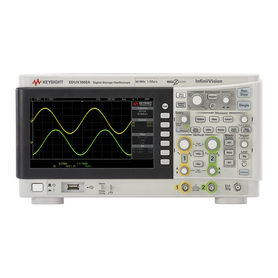
InfiniiVision 1000 X-Series Oscilloscopes—At a Glance DSOX1102AG Digital Storage Oscilloscope 70 M Hz 2 GSa/ s Table 1 1000 X-Series Model Numbers, Bandwidths Model: EDUX1002A EDUX1002G DSOX1102A DSOX1102G Channels: Bandwidth: 50 MHz 70 MHz, 100 MHz with DSOX1B7T102 upgrade Sampling rate: 1 GSa/s 2 GSa/s Memory:... - Page 5 • 50,000 waveforms/second update rate. • All knobs are pushable for making quick selections. • Trigger types: edge, pulse width, and video on EDUX1000-Series models. DSOX1000-Series models add: pattern, rise/fall time, and setup and hold. • Serial decode/trigger options for: I C and UART/RS232 on EDUX1000-Series models.
-
Page 6: In This Guide
In This Guide This guide shows how to use the InfiniiVision 1000 X-Series oscilloscopes. When unpacking and using the • Chapter 1, “Getting Started,” starting on page 13 oscilloscope for the first time, see: When displaying waveforms and • "Running, Stopping, and Making Single acquired data, see: Acquisitions (Run Control)"... - Page 7 When using the oscilloscope's utility • "Utility Settings" on page 88 functions, see: For reference information, see: • "Specifications and Characteristics" on page 91 • "Environmental Conditions" on page 92 • "Probes and Accessories" on page 93 • "Software and Firmware Updates" on page 94 •...
- Page 8 Keysight InfiniiVision 1000 X-Series Oscilloscopes User's Guide...
-
Page 9: Table Of Contents
Contents InfiniiVision 1000 X-Series Oscilloscopes—At a Glance / 4 In This Guide / 6 Getting Started Inspect the Package Contents / 14 Power-On the Oscilloscope / 15 Connect Probes to the Oscilloscope / 16 Maximum input voltage at analog inputs / 16 Do not float the oscilloscope chassis / 16 Input a Waveform / 17 Recall the Default Oscilloscope Setup / 18... - Page 10 Horizontal Controls / 35 Horizontal Knobs and Keys / 35 Horizontal Softkey Controls / 35 Zoom / 36 Vertical Controls / 38 Vertical Knobs and Keys / 38 Vertical Softkey Controls / 38 Setting Analog Channel Probe Options / 40 Analog Bus Display / 41 FFT Spectral Analysis / 42 FFT Measurement Hints / 42...
- Page 11 Cursor Softkey Controls / 63 Measurements / 65 Mask Testing / 67 Creating/Editing Mask Files / 67 Digital Voltmeter / 74 Frequency Response Analysis / 75 Waveform Generator / 77 Serial Bus Decode/Trigger / 78 CAN Decode/Trigger / 79 I2C Decode/Trigger / 80 LIN Decode/Trigger / 80 SPI Decode/Trigger / 81 UART/RS232 Decode/Trigger / 82...
- Page 12 Keysight InfiniiVision 1000 X-Series Oscilloscopes User's Guide...
-
Page 13: Getting Started
Keysight InfiniiVision 1000 X-Series Oscilloscopes User's Guide 1 Getting Started Inspect the Package Contents / 14 Power-On the Oscilloscope / 15 Connect Probes to the Oscilloscope / 16 Input a Waveform / 17 Recall the Default Oscilloscope Setup / 18 Use Autoscale / 19 Compensate Passive Probes / 20 Learn the Front Panel Controls and Connectors / 22... -
Page 14: Inspect The Package Contents
Getting Started Inspect the Package Contents • Inspect the shipping container for damage. If your shipping container appears to be damaged, keep the shipping container or cushioning material until you have inspected the contents of the shipment for completeness and have checked the oscilloscope mechanically and electrically. -
Page 15: Power-On The Oscilloscope
Getting Started Power-On the Oscilloscope Power Line voltage, frequency, and power: Requirements • ~Line 100-120 Vac, 50/60/400 Hz • 100-240 Vac, 50/60 Hz • 50 W max Ventilation The air intake and exhaust areas must be free from obstructions. Unrestricted air Requirements flow is required for proper cooling. -
Page 16: Connect Probes To The Oscilloscope
Getting Started Connect Probes to the Oscilloscope 1 Connect the oscilloscope probe to an oscilloscope channel BNC connector. 2 Connect the probe's retractable hook tip to the point of interest on the circuit or device under test. Be sure to connect the probe ground lead to a ground point on the circuit. -
Page 17: Input A Waveform
Getting Started Input a Waveform The Probe Comp signal is used for compensating probes. 1 Connect an oscilloscope probe from channel 1 to the Demo, Probe Comp terminal on the front panel. 2 Connect the probe's ground lead to the ground terminal (next to the Demo terminal). -
Page 18: Recall The Default Oscilloscope Setup
Getting Started Recall the Default Oscilloscope Setup To recall the default oscilloscope setup: 1 Press [Default Setup]. The default setup restores the oscilloscope's default settings. This places the oscilloscope in a known operating condition. In the Save/Recall menu, there are also options for restoring the complete factory settings or performing a secure erase (see "Save/Recall (Setups, Screens, Data)"... -
Page 19: Use Autoscale
Getting Started Use Autoscale Use [Auto Scale] to automatically configure the oscilloscope to best display the input signals. 1 Press [Auto Scale]. You should see a waveform on the oscilloscope's display similar to this: 2 If you want to return to the oscilloscope settings that existed before, press Undo Autoscale. -
Page 20: Compensate Passive Probes
Getting Started Compensate Passive Probes Each oscilloscope passive probe must be compensated to match the input characteristics of the oscilloscope channel to which it is connected. A poorly compensated probe can introduce significant measurement errors. If your probe has a configurable attenuation setting (like the N2140/42A probes do), the 10:1 NOTE setting must be used for probe compensation. - Page 21 Getting Started 8 Repeat the procedure for each channel. Keysight InfiniiVision 1000 X-Series Oscilloscopes User's Guide...
-
Page 22: Learn The Front Panel Controls And Connectors
Getting Started Learn the Front Panel Controls and Connectors On the front panel, key refers to any key (button) you can press. Softkey specifically refers to the six keys next to the display. Menus and softkey labels appear on the display when other front panel keys are pressed. Softkey functions change as you navigate through the oscilloscope's menus. - Page 23 Getting Started Entry knob The Entry knob is used to select items from menus and to change values. The function of the Entry knob changes based upon the current menu and softkey selections. Note that when the Entry knob symbol appears on a softkey, you can use the Entry knob, to select values.
- Page 24 Getting Started Run Control When the [Run/Stop] key is green, the oscilloscope is running, that is, acquiring data when trigger keys conditions are met. To stop acquiring data, press [Run/Stop]. When the [Run/Stop] key is red, data acquisition is stopped. To start acquiring data, press [Run/Stop].
- Page 25 Getting Started Trigger controls The Trigger controls determine how the oscilloscope triggers to capture data. These controls consist • Level knob — Turn the Level knob to adjust the trigger level for a selected analog channel. Push the knob to set the level to the waveform's 50% value. If AC coupling is used, pushing the Level knob sets the trigger level to about 0 V.
- Page 26 Getting Started Vertical The Vertical controls consist of: controls • Analog channel on/off keys — Use these keys to switch a channel on or off, or to access a channel's menu in the softkeys. There is one channel on/off key for each analog channel. •...
-
Page 27: Front Panel Overlays For Different Languages
Getting Started USB Host port This port is for connecting USB mass storage devices or printers to the oscilloscope. Connect a USB compliant mass storage device (flash drive, disk drive, etc.) to save or recall oscilloscope setup files and reference waveforms or to save data and screen images. See "Save/Recall (Setups, Screens, Data)"... -
Page 28: Learn The Rear Panel Connectors
Getting Started Learn the Rear Panel Connectors For the following figure, refer to the numbered descriptions in the table that follows. 3. USB Device port 2. Kensington lock hole 1. Power cord connector Power cord Attach the power cord here. connector Kensington lock This is where you can attach a Kensington lock for securing the instrument. -
Page 29: Learn The Oscilloscope Display
Getting Started Learn the Oscilloscope Display The oscilloscope display contains acquired waveforms, setup information, measurement results, and the softkey definitions. Analog channel Trigger point, Delay Time/ Run/Stop Trigger Trigger sensitivity time reference time status type source Trigger level Status line Trigger level Softkey labels Analog... - Page 30 Getting Started Softkey labels and When most front panel keys are pressed, short menu names and softkey labels appear in this area. information area The labels describe the softkey functions. Typically, softkeys let you set up additional parameters for the selected mode or menu. Pressing the Back key returns through the menu hierarchy until softkey labels are off and the Back...
-
Page 31: Access The Built-In Quick Help
Getting Started Access the Built-In Quick Help To view Quick Help 1 Press and hold the key, softkey, or knob for which you would like to view help. Quick Help remains on the screen until another key is pressed or a knob is turned. To select the user To select the user interface and Quick Help language: interface and... - Page 32 Getting Started Keysight InfiniiVision 1000 X-Series Oscilloscopes User's Guide...
-
Page 33: Quick Reference
Keysight InfiniiVision 1000 X-Series Oscilloscopes User's Guide 2 Quick Reference Running, Stopping, and Making Single Acquisitions (Run Control) / 34 Horizontal Controls / 35 Vertical Controls / 38 Analog Bus Display / 41 FFT Spectral Analysis / 42 Math Waveforms / 46 Reference Waveforms / 48 Display Settings / 49 Triggers / 52... -
Page 34: Running, Stopping, And Making Single Acquisitions (Run Control)
Quick Reference Running, Stopping, and Making Single Acquisitions (Run Control) To display the results of multiple acquisitions, use persistence. See "Display Settings" on page 49. Single vs. Running The maximum data record length is greater for a single acquisition than when the and Record Length oscilloscope is running (or when the oscilloscope is stopped after running): •... -
Page 35: Horizontal Controls
Quick Reference Horizontal Controls Horizontal Knobs and Keys Horizontal Softkey Controls The following figure shows the Acquire menu which appears after pressing the [Acquire] key. Trigger Time Delay Time/ Trigger Trigger level point reference time source or threshold Normal time mode XY or Roll mode Zoomed... -
Page 36: Zoom
Quick Reference The time reference is indicated at the top of the display grid by a small hollow triangle (∇). Turning the Horizontal scale knob expands or contracts the waveform about the time reference point (∇). The trigger point, which is always time = 0, is indicated at the top of the display grid by a small solid triangle ( ). - Page 37 Quick Reference These markers show the Time/div Time/div Delay time beginning and end of the for zoomed for normal momentarily displays Zoom window window window when the Horizontal position knob is turned Normal window Signal anomaly expanded in zoom window Zoom window Select...
-
Page 38: Vertical Controls
Quick Reference Vertical Controls Vertical Knobs and Keys Keysight recommends always scaling the signal so that the entire waveform is contained NOTE between the top and bottom of the display. For proper operation of the 1000 X-Series oscilloscope, the channel inputs must not be overdriven more than ±8 divisions. - Page 39 Quick Reference Channel, Trigger Trigger level Volts/div source or threshold Channel 1 ground level Channel 2 ground level The ground level of the signal for each displayed analog channel is identified by the position of the icon at the far-left side of the display. Table 4 Vertical Features Feature Front Panel Key/Softkey Location (see built-in help for more information)
-
Page 40: Setting Analog Channel Probe Options
Quick Reference Setting Analog Channel Probe Options In the Channel menu, the Probe softkey opens the Channel Probe menu. This menu lets you select additional probe parameters such as attenuation factor and units of measurement for the connected probe. For correct measurements, you must match the oscilloscope's probe attenuation factor CAUTION settings with the attenuation factors of the probes being used. -
Page 41: Analog Bus Display
Quick Reference Analog Bus Display You can display a bus made up of the analog channel inputs and the external trigger input. Any of the input channels can be assigned to the bus. The bus values display appears at the bottom of the graticule. Channel 1 is the least significant bit and the external trigger input is the most significant bit. -
Page 42: Fft Spectral Analysis
Quick Reference FFT Spectral Analysis FFT is used to compute the fast Fourier transform using analog input channels. FFT takes the digitized time record of the specified source and transforms it to the frequency domain. When the FFT function is selected, the FFT spectrum is plotted on the oscilloscope display as magnitude in dBV versus frequency. - Page 43 Quick Reference While the FFT spectrum is displayed, use the [FFT] and [Cursors] keys to switch between measurement functions and frequency domain controls in FFT Menu. FFT Resolution NOTE The FFT resolution is the quotient of the sampling rate and the number of FFT points (f /N).
-
Page 44: Fft Dc Value
Quick Reference FFT DC Value The FFT computation produces a DC value that is incorrect. It does not take the offset at center screen into account. The DC value is not corrected in order to accurately represent frequency components near DC. FFT Aliasing When using FFTs, it is important to be aware of frequency aliasing. -
Page 45: Fft Spectral Leakage
Quick Reference Figure 2 Aliasing Because the frequency span goes from ≈ 0 to the Nyquist frequency, the best way to prevent aliasing is to make sure that the frequency span is greater than the frequencies of significant energy present in the input signal. FFT Spectral Leakage The FFT operation assumes that the time record repeats. -
Page 46: Math Waveforms
Quick Reference Math Waveforms Math functions can be performed on analog channels and lower math functions. The resulting math waveform is displayed in light purple. Table 8 Math Features Feature Front Panel Key/Softkey Location (see built-in help for more information) Math operator [Math] >... -
Page 47: Units For Math Waveforms
Quick Reference Table 9 FFT (Magnitude), FFT (Phase) Operator Features (continued) Feature Front Panel Key/Softkey Location (see built-in help for more information) Vertical units [Math] > More > Vertical Units (For FFT (Magnitude): Decibels or V RMS. For FFT (Phase): Radians or Degrees.) FFT (Phase) zero [Math] >... -
Page 48: Reference Waveforms
Quick Reference Reference Waveforms Analog channel or math waveforms can be saved to one of two reference waveform locations in the oscilloscope. Then, a reference waveform can be displayed and compared against other waveforms. One reference waveform can be displayed at a time. Table 11 Reference Waveform Features Feature Front Panel Key/Softkey Location (see built-in help for more information) -
Page 49: Display Settings
Quick Reference Display Settings You can adjust the intensity of displayed analog input channel waveforms to account for various signal characteristics, such as fast time/div settings and low trigger rates. You can turn on waveform persistence, where the oscilloscope updates the display with new acquisitions, but does not immediately erase the results of previous acquisitions. -
Page 50: To Load A List Of Labels From A Text File You Create
Quick Reference Table 12 Display Features (continued) Feature Front Panel Key/Softkey Location (see built-in help for more information) Freeze display You must configure the [Quick Action] key to freeze the display. See "Configuring the [Quick Action] Key" on page 90. Many activities, such as adjusting the trigger level, adjusting vertical or horizontal settings, or saving data will un-freeze the display. - Page 51 Quick Reference Label List Management NOTE When you press the Library softkey, you will see a list of the last 75 labels used. The list does not save duplicate labels. Labels can end in any number of trailing digits. As long as the base string is the same as an existing label in the library, the new label will not be put in the library.
-
Page 52: Triggers
Quick Reference Triggers A trigger setup tells the oscilloscope when to acquire and display data. For example, you can set up to trigger on the rising edge of the analog channel 1 input signal. You can use any input channel or the Ext Trig input BNC as the source for most trigger types (see "External Trigger Input"... -
Page 53: Trigger Mode, Coupling, Reject, Holdoff
Quick Reference Table 13 Trigger Type Features Feature Front Panel Key/Softkey Location (see built-in help for more information) Trigger level Turn the trigger Level knob. Also: [Analyze] > Features, Trigger Levels. The edge trigger level for the Line source is not adjustable. This trigger is synchronized with the power line supplied to the oscilloscope. - Page 54 Quick Reference 2 Remove the noise from the trigger path by turning on high-frequency rejection, low-frequency rejection, or noise reject. 3 Use "Selecting the Acquisition Mode" on page 56 to reduce noise on the displayed waveform. Table 14 Trigger Mode, Coupling, Reject, Holdoff Features Feature Front Panel Key/Softkey Location (see built-in help for more information) Trigger mode...
-
Page 55: External Trigger Input
Quick Reference Table 14 Trigger Mode, Coupling, Reject, Holdoff Features (continued) Feature Front Panel Key/Softkey Location (see built-in help for more information) Trigger holdoff [Trigger] > Holdoff The correct holdoff setting is typically slightly less than one repetition of the waveform. External Trigger Input The external trigger input can be used as a source in several of the trigger types. -
Page 56: Acquisition Control
Quick Reference Acquisition Control This section shows how to use the oscilloscope's acquisition controls. Selecting the Acquisition Mode When selecting the oscilloscope acquisition mode, keep in mind that samples are normally decimated (thrown away) at slower time/div settings. At slower time/div settings, the effective sample rate drops (and the effective sample period increases) because the acquisition time increases and the oscilloscope's digitizer is sampling faster than is required to fill memory. -
Page 57: Overview Of Sampling
Quick Reference Table 17 Segmented Memory Acquisition Features, Available on DSOX1000-Series Models Only Feature Front Panel Key/Softkey Location (see built-in help for more information) Segmented memory [Acquire] > Segmented > Segmented, # of Segs, [Run] or [Single] acquisitions After each segment fills, the oscilloscope re-arms and is ready to trigger in about 8 µs. Remember though, for example: if the horizontal time per division control is set to 5 µs/div, and the Time Reference is set to Center, it will take at least 50 µs to fill all ten divisions and re-arm. - Page 58 Quick Reference Figure 3 Aliasing Oscilloscope Bandwidth and Sample Rate An oscilloscope's bandwidth is typically described as the lowest frequency at which input signal sine waves are attenuated by 3 dB (-30% amplitude error). At the oscilloscope bandwidth, sampling theory says the required sample rate is f = 2f .
- Page 59 Quick Reference Figure 4 Theoretical Brick-Wall Frequency Response However, digital signals have frequency components above the fundamental frequency (square waves are made up of sine waves at the fundamental frequency and an infinite number of odd harmonics), and typically, for 500 MHz bandwidths and below, oscilloscopes have a Gaussian frequency response.
- Page 60 Quick Reference Limiting oscilloscope bandwidth (f ) to 1/4 the sample rate (f reduces frequency components above the Nyquist frequency (f Figure 5 Sample Rate and Oscilloscope Bandwidth So, in practice, an oscilloscope's sample rate should be four or more times its bandwidth: f = 4f .
- Page 61 Quick Reference Oscilloscope Bandwidth Required The oscilloscope bandwidth required to accurately measure a signal is primarily determined by the signal's rise time, not the signal's frequency. You can use these steps to calculate the oscilloscope bandwidth required: 1 Determine the fastest edge speeds. You can usually obtain rise time information from published specifications for devices used in your designs.
- Page 62 Quick Reference sample rate = number of samples / time of acquisition For example, when storing 50 µs of data in 50,000 points of memory, the actual sample rate is 1 GSa/s. Likewise, when storing 50 ms of data in 50,000 points of memory, the actual sample rate is 1 MSa/s.
-
Page 63: Cursors
Quick Reference Cursors Cursors are horizontal and vertical markers that indicate X-axis values and Y-axis values on a selected waveform source. You can use cursors to make custom voltage, time, phase, or ratio measurements on oscilloscope signals. Cursor information is displayed at the bottom of the screen. X Cursors X cursors are vertical dashed lines that adjust horizontally and can be used to measure time (s), frequency (1/s), phase (°), and ratio (%). - Page 64 Quick Reference Table 18 Cursor Features Feature Front Panel Key/Softkey Location (see built-in help for more information) Cursors mode [Cursors] > Mode Manual cursors mode [Cursors] > Mode, Manual (and use Cursors knob to select and adjust) Track Waveform [Cursors] > Mode, Track Waveform cursors mode Measure cursors [Meas] (cursors show locations used for most recently added measurement)
-
Page 65: Measurements
Quick Reference Measurements The [Meas] key lets you make automatic measurements on waveforms. Some measurements can be made only on analog input channels. If a portion of the waveform required for a measurement is not displayed or does not display NOTE enough resolution to make the measurement (approximately 4% of full scale), the result will be displayed as greater than a value, less than a value, not enough edges, not enough... - Page 66 Quick Reference Table 19 Measurement Features Feature Front Panel Key/Softkey Location (see built-in help for more information) Measurement type [Meas] > Type: Snapshot all [Meas] > Type: Snapshot All, Add Measurement measurements You can also configure the [Quick Action] key to display the Snapshot All popup. See "Configuring the [Quick Action] Key"...
-
Page 67: Mask Testing
Quick Reference Mask Testing Mask testing is available on the DSOX1000-Series oscilloscope models. One way to verify a waveform's compliance to a particular set of parameters is to use mask testing. A mask defines a region of the oscilloscope's display in which the waveform must remain in order to comply with chosen parameters. - Page 68 Quick Reference Mask Title The Mask Title is a string of ASCII characters. Example: autoMask CH1 OCT 03 09:40:26 2008 When a mask file contains the keyword "autoMask" in the title, the edge of the mask is passing by definition. Otherwise, the edge of the mask is defined as a failure.
- Page 69 Quick Reference The vertices in a mask file are normalized. There are four parameters that define how values are normalized: • X1 • ΔX • Y1 • Y2 These four parameters are defined in the Oscilloscope Setup portion of the mask file.
- Page 70 Quick Reference :MTES:SCAL:Y1 +359.000E-03 :MTES:SCAL:Y2 +2.35900E+00 Building a Mask File The following display shows a mask that uses all eight regions. This mask is created by recalling the following mask file: MASK_FILE_548XX "All Regions" /* Region Number */ 1 /* Number of vertices */ 4 -12.50, MAX -10.00, 1.750 10.00, 1.750...
- Page 71 Quick Reference 02.50, 0.500 05.00, 1.000 02.50, 1.500 -02.50, 1.500 /* Region Number */ 4 /* Number of vertices */ 5 10.00, 1.000 12.50, 0.500 15.00, 0.500 15.00, 1.500 12.50, 1.500 /* Region Number */ 5 /* Number of vertices */ 5 -10.00, -1.000 -12.50, -0.500 -15.00, -0.500...
- Page 72 Quick Reference In a mask file, all region definitions need to be separated by a blank line. Mask regions are defined by a number of (x,y) coordinate vertices (as on an ordinary x,y graph). A "y" value of "MAX" specifies the top of the graticule, and a "y"...
- Page 73 Quick Reference Although a mask can have up to 8 regions, in any given vertical column, it is only possible to NOTE define 4 regions. When there are 4 regions in a vertical column, one region must be tied to the top (using the MAX y value) and one must be tied to the bottom (using the MIN y value).
-
Page 74: Digital Voltmeter
Quick Reference Digital Voltmeter The Digital Voltmeter (DVM) analysis feature provides 3-digit voltage and 5-digit frequency measurements using any analog channel. DVM measurements are asynchronous from the oscilloscope's acquisition system and are always acquiring. Table 21 Digital Voltmeter Features Feature Front Panel Key/Softkey Location (see built-in help for more information) Digital voltmeter [Analyze] >... -
Page 75: Frequency Response Analysis
Quick Reference Frequency Response Analysis On G-suffix oscilloscope models (that have a a built-in waveform generator), the Frequency Response Analysis (FRA) feature controls the built-in waveform generator to sweep a sine wave across a range of frequencies while measuring the input to and output from a device under test (DUT). - Page 76 Quick Reference Table 22 Frequency Response Analysis Features (continued) Feature Front Panel Key/Softkey Location (see built-in help for more information) Adjust scale, offset, [Analyze] > Chart > Select, Entry knob (Gain, Phase, Frequency) and frequency range of gain or phase Bode [Analyze] >...
-
Page 77: Waveform Generator
Quick Reference Waveform Generator On G-suffix oscilloscope models, a waveform generator is built into the oscilloscope. The waveform generator gives you an easy way to provide input signals when testing circuitry with the oscilloscope. Waveform generator settings can be saved and recalled with oscilloscope setups. "Save/Recall (Setups, Screens, Data)"... -
Page 78: Serial Bus Decode/Trigger
Quick Reference Serial Bus Decode/Trigger Depending on the oscilloscope model, the following hardware-accelerated serial decode and trigger options are available: Serial decode and trigger type: Available on: With license: CAN (Controller Area Network) DSOX1000-Series models AUTO I2C (Inter-IC) All 1000 X-Series models EMBD LIN (Local Interconnect Network) DSOX1000-Series models... -
Page 79: Can Decode/Trigger
Quick Reference Table 24 Serial Bus Decode/Trigger Features Feature Front Panel Key/Softkey Location (see built-in help for more information) Serial bus select, [Bus] > Select, Entry knob to select Serial Bus, push Select softkey or Entry knob to enable or enable/disable disable Serial bus mode... -
Page 80: I2C Decode/Trigger
Quick Reference Table 25 CAN Decode/Trigger Features (continued) Feature Front Panel Key/Softkey Location (see built-in help for more information) CAN trigger [Trigger] > Trigger Type, Serial 1 (CAN) [Trigger] > Trigger on: (SOF - Start of Frame, Remote Frame ID (RTR), Data Frame ID (~RTR), Remote or Data Frame ID, Data Frame ID and Data, Error Frame, All Errors, Acknowledge Error, Overload Frame) For triggers where you can specify frame ID or data values, press [Trigger] >... -
Page 81: Spi Decode/Trigger
Quick Reference When interpreting the decode waveforms, see the Mode softkey built-in help. Table 27 LIN Decode/Trigger Features Feature Front Panel Key/Softkey Location (see built-in help for more information) LIN signal setup After selecting the Serial Bus and the LIN serial bus mode, press [Bus] > Signals > to open the LIN Signals menu. -
Page 82: Uart/Rs232 Decode/Trigger
Quick Reference Table 28 SPI Decode/Trigger Features Feature Front Panel Key/Softkey Location (see built-in help for more information) SPI signal setup After selecting the Serial Bus and the SPI serial bus mode, press [Bus] > Signals > to open the SPI Signals menu. - Page 83 Quick Reference Table 29 UART/RS232 Decode/Trigger Features (continued) Feature Front Panel Key/Softkey Location (see built-in help for more information) UART/RS232 parity [Bus] > Bus Config > Parity, Entry knob (Even, Odd, None) UART/RS232 baud [Bus] > Bus Config > Baud Rate > Baud, Entry knob rate UART/RS232 bus...
-
Page 84: Save/Recall (Setups, Screens, Data)
Quick Reference Save/Recall (Setups, Screens, Data) Oscilloscope setups, reference waveforms, and mask files can be saved to internal oscilloscope memory or to a USB storage device and recalled later. You can also recall default or factory default setups. Oscilloscope screen images can be saved to a USB storage device in BMP or PNG formats. -
Page 85: Length Control
Quick Reference Table 30 Save/Recall Features (continued) Feature Front Panel Key/Softkey Location (see built-in help for more information) Save waveform data [Save/Recall] > Save > Format, • CSV data (*.csv) • ASCII XY data (*.csv) • Multi Channel Waveform data (*.h5) •... - Page 86 Quick Reference • Whether reference waveforms are on. Displayed reference waveforms consume acquisition memory. • Whether segmented memory (available on DSOX1000-Series models) is on. Acquisition memory is divided by the number of segments. • The horizontal time/div (sweep speed) setting. At faster settings, fewer data points appear on the display.
-
Page 87: Print (Screens)
Quick Reference Print (Screens) You can print the complete display, including the status line and softkeys, to a USB printer. To set up a USB printer: 1 Connect a USB printer to the USB host port on the front panel. 2 To open the Print Config menu: •... -
Page 88: Utility Settings
Quick Reference Utility Settings This section explains oscilloscope utility functions. Table 32 Utility Features Feature Front Panel Key/Softkey Location (see built-in help for more information) I/O setup [Utility] > I/O > The oscilloscope can be accessed and/or controlled remotely using the USB device port on the rear panel (square shaped USB port). -
Page 89: Usb Storage Devices
Quick Reference Table 32 Utility Features (continued) Feature Front Panel Key/Softkey Location (see built-in help for more information) Acquisition mode [Utility] > Options > Preferences > Autoscale > Acq Mode (Use normal acquisition mode, Preserve during autoscale acquisition mode) Oscilloscope clock [Utility] >... -
Page 90: Configuring The [Quick Action] Key
Quick Reference Most USB mass storage devices are compatible with the oscilloscope. However, certain devices may be incompatible, and may not be able to be read or written to. USB storage devices must be formatted with the FAT or FAT32 file system format. When the USB mass storage device is connected to the oscilloscope's USB host port, a small four-color circle icon may be displayed briefly as the USB device is read. -
Page 91: Specifications And Characteristics
Quick Reference Specifications and Characteristics For up-to-date specifications and characteristics on the 1000 X-Series oscilloscopes, see the data sheet at: www.keysight.com/find/1000X-Series Keysight InfiniiVision 1000 X-Series Oscilloscopes User's Guide... -
Page 92: Environmental Conditions
Quick Reference Environmental Conditions Environment Indoor use only. Ambient Operating: 0 °C to +50 °C temperature Non-operating: -10 °C to +70 °C Humidity Operating: Up to 95% RH, non-condensing to temperatures up to +40 °C decreasing linearly to 50% RH at +50 °C Non-operating: Up to 90% RH up to +65 °C (non condensing) Altitude Operating: to 3,000 m... -
Page 93: Probes And Accessories
Quick Reference Probes and Accessories For a list of the probes and accessories that are compatible with the 1000 X-Series oscilloscopes, see the data sheet at: www.keysight.com/find/1000X-Series Because the 1000 X-Series oscilloscopes do not have a ring around the BNC connector for identifying probes, you must set the probe attenuation factor manually. -
Page 94: Software And Firmware Updates
Quick Reference Software and Firmware Updates From time to time Keysight Technologies releases software and firmware updates for its products. To search for firmware updates for your oscilloscope, direct your web browser to www.keysight.com/find/1000X-Series-sw. To view the currently installed software and firmware press [Help] > About Oscilloscope. -
Page 95: Acknowledgements
Quick Reference Acknowledgements Table 34 Third Party Software Software Description and Copyright License 7-zip Copyright (C) 1999-2016 Igor Pavlov. GNU LGPL + unRAR restriction Boost Libraries Copyright © 2008 Beman Dawes, Rene Rivera Boost Software License (BSL-1.0) HDF5 HDF5 was developed by The HDF Group and by the National Center BSD-style open source... - Page 96 Quick Reference Table 34 Third Party Software (continued) Software Description and Copyright License WCELIBCEX File copyright is held by a file author. MIT License Files created for the first version of the WCELIBCEX project are copyrighted by (c) 2006 Taxus SI Ltd., http://www.taxussi.com.pl See comment in header of source files for more details.
-
Page 97: Product Markings And Regulatory Information
Quick Reference Product Markings and Regulatory Information These symbols are used on the 1000 X-Series oscilloscopes. Symbol Description Caution, risk of electric shock Caution, refer to accompanying documentation This symbol indicates separate collection for electrical and electronic equipment mandated under EU law as of August 13, 2005. All electric and electronic equipment are required to be separated from normal waste for disposal (Reference WEEE Directive 2002/96/EC). - Page 98 Quick Reference Keysight InfiniiVision 1000 X-Series Oscilloscopes User's Guide...
- Page 99 Index Symbols Analyze key, brightness of waveforms, Analyze Segments, built-in help, (-) Width measurement, annotation, adding, bus configuration, UART/RS232, (+) Width measurement, ASCII file format, Bus key, 25, 41, attenuation, probe, buttons (keys), front panel, Numerics attenuation, probe, external trigger, auto mask creation, 10-bit write trigger, I2C, auto range, digital voltmeter,...
- Page 100 Index Conformity, Declaration of, Delay measurement, connectors, rear panel, delay time, factory default settings, control, remote, delete file, Fall time measurement, controls, front panel, Demo terminal, fast debug AutoScale, copyright, digital voltmeter (DVM), FAT file system format, Counter measurement, digital voltmeter mode, FAT32 file system format, counters, CAN, Display key,...
- Page 101 Index frequency response analysis (FRA), humidity (environmental load file, frequency response analysis data, conditions), localized front panel overlay, save, logic presets, waveform generator, frequency, Nyquist, low pass filter, frequency-shift keying modulation low signal, (FSK), waveform generator I/O interface settings, low-frequency noise rejection, output, I2C address size, front panel controls and connectors,...
- Page 102 Index Multiply math function, persistence, infinite, Quick Measure All, mV grid type, Phase measurement, Quick Print, Phase plot in FRA chart, Quick Print quick action, phase X cursor units, Quick Recall, PNG file format, Quick Save, navigate files, points, FRA, quick save to USB storage device, noise rejection, polarity, CAN,...
- Page 103 Index sample rate, oscilloscope, 58, single acquisition, thumb drive, sampling theory, Single key, time, sampling, overview, single-shot acquisitions, time measurements, save, skew, analog channel, time mode, save file, slope trigger, time reference, save segment, Snapshot All measurements, time reference indicator, save setup files, snapshot all, quick action, time, segmented memory re-arm,...
- Page 104 Index Vertical knobs and keys, X at Min Y measurement, vertical position knobs, XY time mode, UART/RS232 base, vertical scale fine adjustment, UART/RS232 baud rate, vertical scale knobs, UART/RS232 bit order, vertical sensitivity, UART/RS232 bus configuration, Vertical softkey controls, Z-axis blanking, UART/RS232 counters, Vertical Units, FFT, zero phase reference, FFT (Phase),...
Need help?
Do you have a question about the InfiniiVision 1000 X Series and is the answer not in the manual?
Questions and answers