
Related Manuals for Transition Networks PointSystem CPSMC1900-100


Summary of Contents for Transition Networks PointSystem CPSMC1900-100
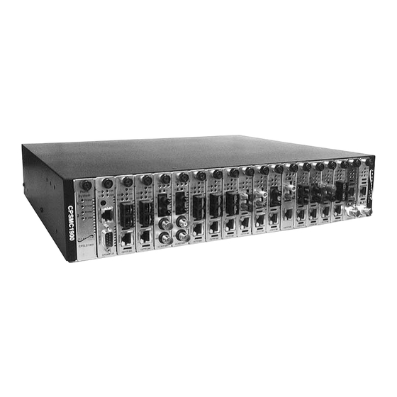
- Page 1 Transition Networks CPSMC19xx-100 19-Slot PointSystem™ Chassis User’s Guide (revision C) CPSMC1900-100 CPSMC1910-100...
-
Page 2: Compliance Information
Compliance Information UL Listed C-UL Listed (Canada) CISPR22/EN55022 Class A + EN55024 CE Mark FCC Regulations This equipment has been tested and found to comply with the limits for a Class A digital device, pursuant to part 15 of the FCC rules. These limits are designed to provide reasonable protection against harmful interference when the equip- ment is operated in a commercial environment. -
Page 3: Table Of Contents
Table of Contents Introduction ........5 Description . - Page 4 CPSMC19xx-100 PointSystem™ Chassis Troubleshooting ........33 Technical Specifications ........34 Cable Specifications .
-
Page 5: Introduction
Introduction Description The Transition Networks CPSMC19xx-100 19-Slot PointSystem™ chassis is a 19- inch, rack-mountable chassis for selected Transition Networks media converter slide-in-modules. The CPSMC19xx-100 allows the network administrator to con- nect various copper and fiber-optic network media over protocols that include Ethernet, Fast Ethernet, DS3/E3, and OC-12 and many others. -
Page 6: Unpacking The Cpsmc19Xx-100 Equipment
(included with the management modules) Expansion Management Module Management Module Cascade Connector Rack Mount Ears Selectable media converter slide-in-module(s) 24-hour Technical Support: 1-800-260-1312 -- International: 00-1-952-941-7600 CPSMC19xx-100 PointSystem™ Chassis Part Number CPSMC1900-100 CPSMC1910-100 CPSFP-200 (varies by country) 33242 Part Number CPSMP-200 (optional) CPSMP-210 (optional) -
Page 7: Slide-In-Modules
Slide-in-Modules Media Converter Slide-in-Modules Transition Networks media converter slide-in-modules, installed in slots at the front of the chassis, allow the network administrator to connect various copper and fiber- optic network media over protocols that include Ethernet, Fast Ethernet, DS3/E3, and OC-12 as well as many others (see www.transition.com for a complete listing.) NOTE: Refer to the user’s guide that comes with each media converter slide-in- module for cable, connector, and LED indicator information specific to that media converter slide-in-module. -
Page 8: Installing The Media Converter Slide-In-Modules
2.1.3 Installing the Media Converter Slide-in-Modules CAUTION: Wear a grounding device and observe electrostatic discharge precau- tions when installing the media converter slide-in-module(s) into the chassis. Failure to observe this caution could result in damage to, and subsequent failure of, the media converter slide-in-module(s). -
Page 9: Replacing The Media Converter Slide-In-Modules
2.1.4 Replacing the Media Converter Slide-in-Modules CAUTION: Wear a grounding device and observe electrostatic discharge precau- tions when replacing media converter slide-in-module(s). caution could result in damage to, and subsequent failure of, the media converter slide-in-module(s). NOTE: The media converter slide-in-modules can be hot-swapped. To replace a media converter slide-in-module in the CPSMC19xx-100 chassis: 1. -
Page 10: Management Modules
Management Modules Optional network management is provided by SNMP software embedded in Transition Networks PointSystem the CPSMC19xx-100 chassis. Transition Networks provides two such modules: • CPSMM-120 Single-Slot Master Management Module. • CPSMM-200 Dual-Slot Master Management Module. Along with an additional expansion module: •... -
Page 11: Installing The Management Modules
2.2.2 Installing the Management Modules CAUTION: Wear a grounding device and observe electrostatic discharge precau- tions when installing the management module into the CPSMC19xx-100 chassis. Failure to observe this caution could result in damage to, and subsequent failure of, the management module. NOTE: Transition Networks recommends installing the management module into the left-most installation slot to keep the management module cables separate from the media converter cables. -
Page 12: Replacing The Management Modules
2.2.3 Replacing the Management Modules CAUTION: Wear a grounding device and observe electrostatic discharge precau- tions when replacing the media converter slide-in-module(s). this caution could result in damage to, and subsequent failure of, the management module(s). NOTE: The management modules can be replaced while the chassis remains pow- ered. -
Page 13: Optional Led Slide-In-Module
Optional LED Slide-in-Module The optional LED slide-in-module (CPSLD-100) allows the network administrator to determine at a glance which power supplies are installed and in use. The LED module can be installed in any slot in the front of the chassis. The proce- dure to install and replace it is the same as any other slide-in-module. -
Page 14: Powering The Cpsmc19Xx-100
Powering the CPSMC19xx-100 AC Power Supply Module The CPSMC1900-100 PointSystem™ chassis is equipped with an AC power supply module (P/N CPSMP-200) installed in the back of the chassis. The power supply module supplies power to the chassis, installed media converter slide-in-modules, management modules, and the optional fan module. - Page 15 Powering the AC Power Supply Module To power the CPSMC1900-100 PointSystem™ chassis through the AC power sup- ply module: 1. Set the On/Off switch to “0”. 2. Connect female end of the power cord to the AC power connector on the power supply module.
-
Page 16: Dc Power Supply Module
DC Power Supply Module The CPSMC1910-100 PointSystem™ chassis is equipped with a DC power supply module (P/N CPSMP-210) installed in the back of the chassis. The power supply module supplies power to the chassis, installed media converter slide-in-modules, management modules, and the optional fan module. Power LED The components of the DC power supply module include: •... - Page 17 Read and follow all warning notices & instructions marked on the product or included in the manual. CAUTION: All installation and service must be performed by qualified service personnel. CAUTION: Ensure that the external power source is NOT powered and that the On/Off switch is set to “0”...
-
Page 18: Optional Dual Power Supply Modules
Optional Dual Power Supply Modules Alternatively, both an AC power supply module and a DC power supply module can be installed in the same chassis. NOTE: The drawing below shows the AC module in the left installation slot and the DC module in the right, However, either power supply module can be installed in either installation space. -
Page 19: Power Supply Module Maintenance
Power Supply Module Maintenance 3.4.1 Primary/Secondary-Management/Manual Switch Both the AC (CPSMP-200) and DC (CPSMP-210) power supply modules have a set of Primary/Secondary-Management/Manual switches installed on the circuit board. Management/Manual Switch The Management/Manual switch allows the PointSystem™ software to control and override the physical setting on the Primary/Secondary switch. -
Page 20: Installing The Power Supply Module
WARNING: Do NOT connect the power supply module to the external power before installing it into the chassis. Failure to observe this caution could result in equipment damage and/or personal injury or death. 3.4.2 Installing the Power Supply Module The AC and DC modules are installed in the same manner. NOTE: At least one power supply module must be set to ‘Primary.’... -
Page 21: Replacing The Power Supply Module
WARNING: Do NOT connect the Power Supply Module to the external power before installing it into the chassis. Failure to observe this caution could result in equipment damage and/or personal injury or death. 3.4.3 Replacing the Power Supply Module The AC and DC modules are replaced in the same manner. Both the AC (CPSMP-200) and DC (CPSMP-210) power supply modules may be hot swapped provided the module to be swapped has been disconnected from the external power source and the On/Off switch has been set to “0”. -
Page 22: 3.4.3 Replacing The Power Supply Fuses
WARNING: Do NOT connect the power supply module to the external power before installing it into the chassis. Failure to observe this caution could result in equipment damage and/or personal injury or death. 3.4.3 Replacing the Power Supply Fuses Replacing the AC Fuse CAUTION: Wear a grounding device and observe electrostatic discharge precau- tions when replacing the fuse in the power supply module. - Page 23 WARNING: Do NOT connect the power supply module to the external power before installing it into the chassis. Failure to observe this caution could result in equipment damage and/or personal injury or death. Replacing the DC Fuse CAUTION: Wear a grounding device and observe electrostatic discharge precau- tions when replacing the fuse in the power supply module.
-
Page 24: Optional Fan Module
Optional Fan Module The optional fan module (CPSFM-200) can be installed in the extra installation space in the back of the CPSMC19xx-100 chassis to provide additional cooling for the entire chassis. CAUTION: Wear a grounding device and observe electrostatic discharge precau- tions when installing the fan module into the chassis. -
Page 25: Table Top Installation
CPSMC19xx-100 Chassis Installing the CPSMC19xx-100 Chassis The CPSMC19xx-100 can be installed in a standard 19-inch rack or on a table, shelf, or other stable surface. CAUTION: Install the chassis so that the air flow around it is not restricted. 4.1.1 Table-Top Installation The CPSMC19xx-100 chassis is shipped with nine (9) rubber feet for optional instal- lation on a table or other flat, stable surface in a well-ventilated area. - Page 26 To install the CPSMC19xx-100 chassis into a standard 19-inch rack: 1. Determine the preferred alignment of the chassis in the rack. NOTE: Installation bracket mounting screws are provided. Rack mount screws and clip nuts are NOT provided. 2. Locate six (6) installation bracket mounting screws (provided) for each chassis to be installed.
-
Page 27: Grounding Lugs
4.1.3 Grounding Lugs The CPSMC19xx-100 comes equipped with grounding lugs, which are provided for a grounding conductor wire terminated with a two-hole, compression-type, ground- ing connector. The grounding wire -- which must be a copper conductor -- is not included with the chassis and must be provided by the customer/installer. The electrical conducting path from the chassis must: •... -
Page 28: Cascade Option
Cascade Option The management module cascade option allows the network administrator to con- nect up to eight (8) CPSMC19xx-100 chassis into one manageable stack, providing a single management source for up to 143 conversion devices. To create the cascade option, the CPSMM-200 Dual Slot Master Management Module is installed in the first chassis in the series. - Page 29 Cascading multiple CPSMC19xx-100 chassis To cascade two or more CPSMC19xx-100 chassis: 1. Locate one (1) Transition Networks management module cascade cable (with RJ-45 connectors installed at both ends) (P/N 6026) for each set of two (2) chassis to be cascaded. NOTE: Transition Networks management module cascade cables are one (1) meter long.
-
Page 30: Connecting The Slide-In-Modules To The Network
Connecting the Slide-in-Modules to the Network Once the CPSMC19xx-100 chassis has been installed, the media converter slide-in- modules may be connected to the network. CAUTION: Connect input/output network cables ONLY to media converter slide- in-module connectors within the same network protocol (such as Ethernet-to- Ethernet, Fast Ethernet-to-Fast Ethernet, ATM-to-ATM). -
Page 31: Network Management
Network Management The CPSMM100 firmware and the FocalPoint™ application are described in the FocalPoint™ 2.0 Management Application and CPSMM100 Firmware user’s guide (P/N 33293). This manual is included on the application CD and is also available on-line at www.transition.com. Transition Networks CPSMM100 firmware is embedded in the optional manage- ment modules (see section 2.2). - Page 32 DB-9 Serial Port The DB-9 serial port allows the network administrator to configure and manage the CPSMC19xx-100 chassis using the SNMP Command-Line Interface (CLI) at an attached terminal or terminal emulator. Use a null modem cable to attach a terminal to the DB-9 serial port on the manage- ment module as shown.
-
Page 33: Troubleshooting
Troubleshooting 1. Are any of the power LEDs on any of the slide-in-modules illuminated, AND are the fans operating? • The chassis is receiving power. Proceed to the next step. • Check all power supply cables for proper connection. • For AC power: Ensure the AC receptacle on the wall is supplying power. -
Page 34: Technical Specifications
Technical Specifications For use with Transition Networks Model CPSMC19xx-100 or equivalent. Dimensions Weight MTBF (Mean Time Before Failure) CPSMC1900 + CPSMP-200 CPSMC1900 + CPSMP-210 CPSMP-200 Power Input: Power Output: CPSMP-210 Power Input: Power Output: Environment Tmra*: Storage Temperature: Humidity Altitude Compliance Warranty Product is certified by the manufacturer to comply with DHHS Rule 21/CFR, Subchapter J applicable at the date... -
Page 35: Cable Specifications
Cable Specifications Null Modem Cable The Null Modem Cable is used for connecting a terminal or terminal emulator to the management module’s DB-9 connector to access the command-line interface. The table below shows the pin assignments for the DB9 cable. Function Carrier Detect Receive Data... -
Page 36: Coax Cable
COAX Cable Coaxial cable media is used for circuits such as DS3, E1 and 10Base-2 Ethernet. The impedance of the coaxial cable is determined by the interface type, for exam- ple: • 75 ohm for DS3. • 50 ohm for 10Base-2 Ethernet. Special attention should be given to the grounding requirements of coaxial cable circuits. -
Page 37: Contact Us
Transition Networks 6475 City West Parkway, Minneapolis MN 55344 USA Model: PointSystem Part Number: CPSMC1900-100, CPSMC1910-100 Regulation: EMC Directive 89/336/EEC Purpose: To declare that the PointSystem formity with the following standards. EN 55022:1998+A1:2000 Class A; FCC Part 15 Subpart B; UL 1950; 21 CFR Subpart J I, the undersigned, hereby declare that the equipment specified above conforms to the above Directive(s) and Standard(s). -
Page 38: Warranty
Warranty Limited Lifetime Warranty Effective for products shipped May 1, 1999 and after. Every Transition Networks' labeled product purchased after May 1, 1999 will be free from defects in material and workmanship for its lifetime. This warranty covers the original user only and is not transferable. - Page 39 CPSMC19xx-100 PointSystem ™ Chassis Before making any non-warranty repair, Transition Networks requires a $200.00 charge plus actual shipping costs to and from the customer. If the repair is greater than $200.00, an estimate is issued to the customer for authorization of repair. If no authorization is obtained, or the product is deemed not repairable, Transition Networks will retain the $200.00 service charge and return the product to the cus- tomer not repaired.
- Page 40 CPSMC19xx-100 PointSystem™ Chassis...
Need help?
Do you have a question about the PointSystem CPSMC1900-100 and is the answer not in the manual?
Questions and answers