Table of Contents
Advertisement
Quick Links
Advertisement
Table of Contents

Related Manuals for Transition Networks ION219 Series


Summary of Contents for Transition Networks ION219 Series
- Page 2 All trademarks and registered trademarks are the property of their respective owners. Copyright Notice/Restrictions Copyright © 2010-2018 Transition Networks/ All rights reserved. No part of this work may be reproduced or used in any form or by any means (graphic, electronic or mechanical) without written permission from Transition Networks.
- Page 3 Transition Networks ION219-x Install Guide Cautions and Warnings Definitions Cautions indicate that there is the possibility of poor equipment performance or potential damage to the equipment. Warnings indicate that there is the possibility of injury to person. Cautions and Warnings appear here and may appear throughout this manual where appropriate. Failure to read and understand the information identified by this symbol could result in poor equipment performance, damage to the equipment, or injury to persons.
- Page 4 Transition Networks ION219-x Install Guide Warnings Warning: Use of controls, adjustments or the performance of procedures other than those specified herein may result in hazardous radiation exposure. Warning: Visible and invisible laser radiation when open. Do not look into the beam or view the beam directly with optical instruments.
-
Page 5: Table Of Contents
Transition Networks ION219-x Install Guide Contents 1. Introduction and Description ........................... 8 Product Description ..............................8 Features ..................................8 Ordering Information .............................9 ION219-x Chassis Specifications .......................... 10 IONPS-x Power Supply Specifications ........................11 About this Manual ............................... 11 Related Manuals and Online Help ........................11 Unpacking ................................ - Page 6 Transition Networks ION219-x Install Guide SIC Monitoring ..............................24 Network Management ............................24 Firmware and FocalPoint Applications ......................24 5. Troubleshooting ............................25 Introduction ................................. 25 Record Model and System Information ......................26 Limited Lifetime Warranty ..........................27 Contact Us ................................27 Technical Support ............................
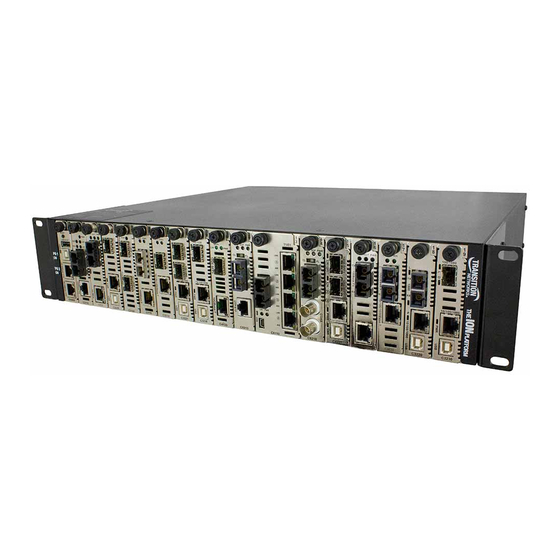
- Page 7 Transition Networks ION219-x Install Guide Figures Figure 1: ION219-x Chassis ............................9 Figure 2: Unpacking ..............................12 Figure 3: ION219-x Chassis Front ..........................13 Figure 4: ION219-x Chassis Rear View ........................14 Figure 5: Unsafe Lifting Techniques ........................15 Figure 6: Rack Mount Ear Installation Positions ...................... 17 Figure 7: ION219-x Rack Mount Ear Installation .....................
-
Page 8: Introduction And Description
ION chassis with the modules in another ION chassis, an ION stand-alone, or a Transition Networks’ Point System™ stand-alone device. To take full advantage of all the features and functions available with the ION Chassis, an ION Management Module (IONMM) is required. -
Page 9: Ordering Information
(included) America, -JP = Japan, -OZ = Australia, -BR = Brazil. Note: Only for ION219-A and ION219-AAMB. Transition Networks offers a full line of small form factor pluggable (SFP) transceivers and passive coarse wave division multiplexing (CWDM) filters. SFPs See the Transition Networks SFP page for details. -
Page 10: Ion219-X Chassis Specifications
Transition Networks ION219-x Install Guide ION219-x Chassis Specifications The ION219-x chassis was designed to meet these standards: Slots 19 Slots in front for ION slide in-cards and 2 Slots in rear for power supply modules. IEEE Standards IEEE 802.3™-2000 Unit LEDs Power On LED for each installed power supply module. -
Page 11: Ionps-X Power Supply Specifications
Support Library (no logon required). For SFP manuals see Transition Networks webpage. Note that this manual provides links to third part web sites for which Transition Networks is not responsible. Other ION System and related device manuals are listed below. •... -
Page 12: Unpacking
Transition Networks ION219-x Install Guide Unpacking 1. Carefully unpack all ION219-x contents. 2. Verify receipt of all ION219-x components. Contact your sales representative if any items are missing. 3. Place the ION219-x and related materials near the install location. 4. Save the ION219-x shipping carton and packing materials for possible future use. -
Page 13: Site Preparation
(NMS) such as SNMPc, HPOV or any other standard SNMP platform. • Focal Point: Transition Networks offers a free SNMP graphical user interface (GUI) software for management purposes. Focal Point offers full read and read/write capabilities in a user friendly GUI. -
Page 14: Chassis Rear
Transition Networks ION219-x Install Guide Chassis Rear The ION219-x is equipped with an AC power supply or an optional DC power supply installed in one of its rear slots. An extra installation space is available for an optional (AC or DC) power supply for redundancy purposes. -
Page 15: Installation
Transition Networks ION219-x Install Guide 3. Installation This chapter describes ION219-x cautions/warnings, site requirements, installation and setup. Cautions Caution: Install the ION219-x chassis so that the airflow around it is not restricted. Failure to observe this caution could result in performance problems or damage to the contents of the chassis. -
Page 16: Site Requirements
Transition Networks ION219-x Install Guide WARNING: Do not work on the chassis, connect, or disconnect cables during a storm with lightning activity. Failure to observe this warning could result in an electrical shock or death. Site Requirements To assure normal operation and avoid unnecessary maintenance, plan the site configuration and prepare the site before installation. -
Page 17: Installation Procedures
Transition Networks ION219-x Install Guide Installation Procedures Installing the Chassis The ION219-x chassis can be installed in a standard 19-inch rack or on a table, shelf, or other stable surfaces. Tabletop Installation The ION219-x chassis comes with nine (9) rubber feet for installation on a table or other flat, stable surface in a well-ventilated area. -
Page 18: Figure 7: Ion219-X Rack Mount Ear Installation
Transition Networks ION219-x Install Guide Installing Rack Mount Ears Note: Installation rack-mount-ear mounting screws (cover-to-frame screws, see Figure 7 below) are provided. Rack mount “screws” and “clip nuts” are NOT provided. To install the ION219-x chassis rack mount ears, do the following: 1. -
Page 19: Rack Installation Procedure
Transition Networks ION219-x Install Guide Rack Installation Procedure To install the chassis in a rack, do the following: 1. Locate four (4) mounting screws (not provided) and optional clip-nuts (not provided) for each chassis to be installed. 2. Carefully position and align the chassis to the mounting holes in the rack, as shown in Figure 8 below. -
Page 20: Grounding Path
Transition Networks ION219-x Install Guide Grounding Path The electrical conducting path from the chassis to ground must: • Flow via the grounding lugs to the Common Bonding Network (CBN) for telecom installations, or to an alternate approved grounding system (if required) for non-telecom installations. -
Page 21: Ground Installation
Transition Networks ION219-x Install Guide Ground Installation To ground the ION219-A chassis, do the following: 1. Obtain one (1) properly terminated, grounding conductor (12 AWG copper wire gauge or larger) with a two- hole, compression-type, grounding connector. Note the manufacturer's applied torque required for the connector. -
Page 22: Chassis Power Leds
Transition Networks ION219-x Install Guide Chassis Power LEDs The power LEDs are located left side of the chassis front panel. The LEDs indicate power supply ON/Ready state. See Figure 11 below. Figure 11: Power Supply LEDs Power Indicator LEDs Power LED indicators present the state of each installed power supply. The LED will light when the respective power supply (PS1 or PS2) is plugged into power with the power ON/OFF switch in the ON position. -
Page 23: Powering The Ion219-X Chassis
Transition Networks ION219-x Install Guide Powering the ION219-x chassis The ION219-x chassis has several power options. The following sections provide specific information on and Warnings and Cautions specific to IONPS-A and IONPS-D Power Supply Components, Optional Power Supply Module Installation, Connecting External Power, Replacing Power Supply Fuse, Replacing the Power Supply... -
Page 24: Network Connectivity
SICs in the ION219-x chassis from an attached terminal or from a remote, networked computer. The firmware includes the Transition Networks Command Line Interface (CLI), a telnet server, a Web browser, and an SNMP (Simple Network Management Protocol) agent. -
Page 25: Troubleshooting
Transition Networks ION219-x Install Guide 5. Troubleshooting Introduction This section provides basic troubleshooting information for the ION219-x chassis via a problem and cause table. The problems are stated in the problem column and the potential cause is listed in the cause column. If the problem cannot be remedied, based on the information below, contact Technical Support. -
Page 26: Record Model And System Information
Describe any action(s) already taken to resolve the problem (e.g., changing mode, resetting, etc.): _________________________________________________________________________________________ _________________________________________________________________________________________ _________________________________________________________________________________________ The model # and serial # of all other Transition Networks products in the network: ________________________ _________________________________________________________________________________________ _________________________________________________________________________________________ Describe your network environment (layout, cable type, cable distance, etc.): ___________________________... -
Page 27: Limited Lifetime Warranty
ION219-x Install Guide Limited Lifetime Warranty To return a defective product for warranty coverage, contact Transition Networks’ technical support department for a return authorization number. Transition Network's technical support department can be reached 24-hours a day by any of the following means:... -
Page 28: European Regulations
Transition Networks ION219-x Install Guide European Regulations CAUTION: This is a Class A product. In a domestic environment, this product could cause radio interference in which case the user may be required to take adequate measures. Achtung ! Dieses ist ein Gerät der Funkstörgrenzwertklasse A. In Wohnbereichen können bei Betrieb dieses Gerätes Rundfunkstörungen auftreten. -
Page 29: Electrical Safety Warnings
Transition Networks ION219-x Install Guide Electrical Safety Warnings Electrical Safety IMPORTANT: This equipment must be installed in accordance with safety precautions. Elektrische Sicherheit WICHTIG: Für die Installation dieses Gerätes ist die Einhaltung von Sicherheitsvorkehrungen erforderlich. Elektrisk sikkerhed VIGTIGT: Dette udstyr skal installeres i overensstemmelse med sikkerhedsadvarslerne. -
Page 30: Appendix A - Cable Specification And Connectors
Transition Networks ION219-x Install Guide Appendix A - Cable Specification and Connectors RJ45 Cable Wire: Category 5e, 6 Gauge: 24 to 22 AWG Attenuation: 22.0 dB/100m @ 100 MHz Max. Cable Distance: 100 meters • Straight-through or crossover cable may be used. -
Page 31: Coax Cable And Bnc Connectors
Transition Networks ION219-x Install Guide Coax Cable and BNC Connectors BNC (Bayonet Neil-Concelman) are bayonet type connectors, commonly used in CCTV systems. These connectors are specified by IEC standard IEC60169-8. BNC coaxial-cable media is used for circuits such as DS3, E1, and 10Base-2 Ethernet. -
Page 32: Usb (Universal Serial Bus)
Transition Networks ION219-x Install Guide USB (Universal Serial Bus) USB uses 4 shielded wires: • two for power (+5v and GND) • two for differential data signals (labelled as D+ and D- in pinout) NRZI (Non Return to Zero Invert) encoding scheme used to send data with a sync field to synchronize the host and receiver clocks. -
Page 33: Fiber Cables
100/140 4.5/2.0/— 200/200 0.29 Fiber Connectors The following are typical connector ends for fiber cables used to connect Transition Networks NIDs and media converters. See Figure 31 below. Figure 16: Fiber Optic Cable Connector Ends 33412 Rev. C https://www.transition.com Page 33 of 34... - Page 34 +1.952.941.7600 | toll free: 1.800.526.9267 | fax: 952.941.2322 sales@transition.com techsupport@transition.com customerservice@transition.com Copyright © 2010-2020 Transition Networks. All rights reserved. Printed in the U.S.A. ION219-x 19-Slot ION Chassis Install Guide, 33412 Rev. C 33412 Rev. C https://www.transition.com Page 34 of 34...
Need help?
Do you have a question about the ION219 Series and is the answer not in the manual?
Questions and answers