Burkert 3323 Series Quick Start Manual
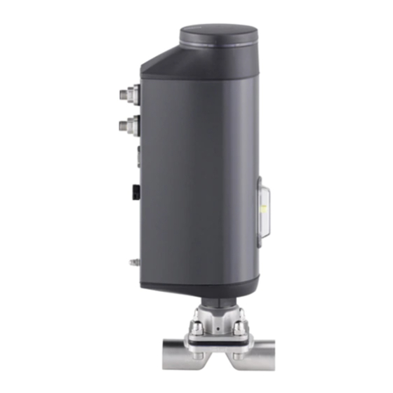
Electromotive diaphragm valve
Hide thumbs
Also See for 3323 Series:
- Operating instructions manual (130 pages) ,
- Quick start manual (44 pages) ,
- Operating instructions manual (122 pages)

Related Manuals for Burkert 3323 Series


Summary of Contents for Burkert 3323 Series
- Page 1 Type 3323, 3324, 3325 AE3323 Electromotive diaphragm valve Elektromotorisches Membranventil Vanne à membrane électromotorisée Quickstart English Deutsch Français...
- Page 2 We reserve the right to make technical changes without notice. Technische Änderungen vorbehalten. Sous réserve de modifications techniques. © 2016 - 2021 Bürkert Werke GmbH & Co. KG Operating Instructions 2104/03_EU-ML_00810539 / Original DE...
-
Page 3: Table Of Contents
Type 3323, 3324, 3325 Table of Contents 7.4 After installation ............23 QUICKSTART ................ 5 7.5 Rotating the actuator ..........23 1.1 Definition of terms ............5 7.6 Holding device ............24 1.2 Means of representation ..........5 ELECTRICAL INSTALLATION ..........24 INTENDED USE ..............6 8.1 E lectrical installation with circular plug-in connector 24 BASIC SAFETY INSTRUCTIONS .......... - Page 4 Type 3323, 3324, 3325 14.1 Visual inspection ............39 14.2 Replacing the diaphragm .......... 40 15 CLEANING ................41 16 ACCESSORIES ..............41 16.1 Communication software .......... 41 17 DISASSEMBLY ..............42 18 DISPOSAL ................42 19 TRANSPORT AND STORAGE ..........42 english...
-
Page 5: Quickstart
▶ Failure to observe these instructions may result in serious ▶ Read these instructions carefully. injuries or death. ▶ Observe in particular the safety instructions, intended use and operating conditions. CAUTION! ▶ Persons who work on the device must read and understand these instructions. Warns of a potential danger. ▶ Failure to observe these instructions may result in moderate The operating instructions can be found on the internet at: or minor injuries. country.burkert.com NOTE! Warns of damage. Definition of terms • Device: The term “device” used in these instructions applies to Important tips and recommendations. the electromotive diaphragm valve types 3323, 3324 and 3325. • The abbreviation “Ex” used in these instructions stands for “potentially explosive”. Refers to information in these operating instructions or in • In these instructions, the unit bar stands for relative pressure. other documentation. -
Page 6: Intended Use
Type 3323, 3324, 3325 Intended use INTENDED USE BASIC SAFETY INSTRUCTIONS These safety instructions do not take into account any unforeseen Improper use of the electromotive diaphragm valve type circumstances and events which occur during installation, operation 3323, 3324 and 3325 may be dangerous to people, nearby and maintenance. equipment and the environment. The operator is responsible for observing the location-specific safety The electromotive diaphragm valve is designed to control the flow regulations, also with reference to personnel. - Page 7 Type 3323, 3324, 3325 Basic safety instructions ▶ If the position of the valve has a bearing on safety concerns ▶ Do not make any internal or external changes to the device in the event of a power failure: Only use devices that have a and do not subject it to mechanical stress. SAFEPOS energy-pack (optional energy-pack). ▶ Transport, install and dismantle a heavy device only with the ▶ Select a valve position that is safe in respect of the process aid of a second person and using suitable equipment. using the DIP switch. ▶ Secure the device against unintentional activation. Danger due to loud noises. ▶ Only trained technicians carry out installation and mainte- ▶ Depending on the usage conditions, the device may generate nance work. loud noises. Detailed information on the probability of loud noises ▶ Following an interruption in the power supply, ensure that is available from the respective sales department. the process is restarted in a controlled manner. Observe the ▶ Wear hearing protection when in the vicinity of the device. sequence. 1. Connect supply voltage.
-
Page 8: General Notes
STRUCTURE AND FUNCTION The electromotive diaphragm valve consists of an electromotively Contact address driven linear actuator and a diaphragm valve body. Germany The control electronics and “SAFEPOS energy-pack” are housed Bürkert Fluid Control Systems in the side of the linear actuator. The control electronics consist Sales Center of the microprocessor-controlled electronic mechanism and the Christian-Bürkert-Str. 13-17 position sensor. D-74653 Ingelfingen Structure of the electromotive Tel. + 49 (0) 7940 - 10-91 111 diaphragm valve Fax + 49 (0) 7940 - 10-91 448 E-mail: info@burkert.com Blind cover with Electrical con- indicator light and nectors (circular International bayonet catch plug-in connector Actuator cover The contact addresses can be found on the back pages of the or cable gland) printed operating instructions. Actuator housing Also on the Internet at: country.burkert.com Pressure compen- Transparent... -
Page 9: Display Of The Device Status
Type 3323, 3324, 3325 Technical data Display of the device status TECHNICAL DATA Various LED modes may be configured to display the device’s The following product-specific information is provided status and valve position (refer to main instructions for on the type label: description). • Voltage [V] (tolerance ± 10%) and current type Factory-set LED mode: “Valve mode + warnings”. • Diaphragm material and valve body material 5.2.1 Displays in valve mode + warnings • Fieldbus standard If device status “Normal”: Continuously lit in the colour of the •... -
Page 10: Type Label
Type 3323, 3324, 3325 Technical data Type label 6.4.1 UL additional label (example) Example: Type AE3323 Valve body material Line connection Da (ø outside), Di (ø inside) Flow Power Supply capacity SELV/PELV only! Maximum permitted medium pressure, LISTED diaphragm material, diaphragm size Process control equipment Voltage, direct current, max. current consumption E238179 Type, function, fieldbus standard Fig. 3: UL additional label (example) 3323 ON/OFF control AS-Interface Labelling housings U = 24V Imax = 3A Pmed10 bar EPDM 40 Batch... -
Page 11: Operating Conditions
Type 3323, 3324, 3325 Technical data WARNING! Company ID Material Reduced sealing function if operating pressure too high. Batch number 1.4435 316L(VP) XXXXXXXX Since the diaphragm valve is closed against the medium flow, PN16 / CWP150 too high an operating pressure can cause the valve not to close tightly. DN value and pipe ▶ The operating pressure must not exceed the maximum value dimensions specified on the type label. Danger from leakage of hot medium The diaphragm does not provide permanent protection against Production number Inclination angle XXXXXXXXXX hot medium. - Page 12 Type 3323, 3324, 3325 Technical data 6.6.1 Permitted temperature ranges ▶ The functional properties and service life of the diaphragm may be diminished if the medium temperature is too high or The permitted temperature ranges for the medium and too low. surrounding environment are dependent on various factors: Permitted medium temperature for diaphragm material: • Medium temperature: Dependent on valve body material and diaphragm material. Diaphragm Temperature Steam sterilisation material range • Ambient temperature: Dependent on medium temperature. PTFE/EPDM (EA) -10...+130 °C +140 °C/60 min. All factors must be taken into consideration when calcu- EPDM (AD), lating permitted temperatures.
- Page 13 Type 3323, 3324, 3325 Technical data Permitted medium temperature for plastic valve body The maximum medium temperature for valve bodies made of plastic depends on the operating pressure. DN 15 - 40 PVDF 20 40 60 80 100 120 140 Temperature [°C] Fig. 6: Diagram: Medium temperature and operating pressure for plastic valve bodies Medium temperature [°C] Temperature diagram The maximum permitted temperature for the environment and...
-
Page 14: General Technical Data
Type 3323, 3324, 3325 Technical data Electrical data General technical data Materials WARNING! A ctuator: PPS and aluminium, powder-coated Electrical shock. V alve body M etal: Stainless steel ingot material (types Protection class III is only guaranteed when using an SELV or 3324 and 3325), investment casting, forged PELV power supply unit. steel, tube valve body. Plastic: PP, PVC and PVDF Protection class: 3 according to DIN EN 61140 (VDE 0140) B ody... - Page 15 Type 3323, 3324, 3325 Technical data EPDM, depending on diaphragm size PTFE, depending on diaphragm size Medium pressure in [bar] Medium pressure in [bar] Fig. 8: Energy consumption actuator, EPDM depending on diaphragm Fig. 9: Energy consumption actuator, PTFE depending on diaphragm size size SAFEPOS energy-pack C harging time: maximum 100 seconds (dependent on operating conditions) S ervice life: up to 10 years (depending...
-
Page 16: Installing The Valve
Type 3323, 3324, 3325 Installing the valve INSTALLING THE VALVE NOTE! WARNING! Consider voltage drop on power supply cable. Example: with a cable cross-section of 0.34 mm , a copper Risk of injury due to improper installation. cable may be a maximum of 8 metres long. ▶ Installation may be carried out by trained technicians only with the appropriate tools. ▶ Secure the system against unintentional activation. Digital outputs (optional): ▶ After installation, ensure that the process is restarted in a Current limit 100 mA controlled manner. Observe the sequence. 1. Connect supply voltage. Digital input for position 2. Charge the device with medium. -
Page 17: Installation Position Of The Diaphragm Valves
Type 3323, 3324, 3325 Installing the valve Installation position of the diaphragm 7.1.2 Installation position for T-body valves Recommended installation position: Depending on the valve body, the installation position for the For supply of medium For removal of medium diaphragm valve is different. One of the relief bores in the diaphragm socket for moni- toring leakages must be at the lowest position. 7.1.1 Installation position for 2-way enclosure Installation position: Arbitrary, ideally with actuator facing upwards. Ensure self-drainage: → Install the valve body at an angle α = 10°...55° inclined to the Fig. -
Page 18: Installation Of Devices With Threaded Connection, Flange Connection, Clamp Connection, Bonded Connection
Risk of injury from high pressure. Installation of devices with welded ▶ Before working on the system, switch off the pressure and connections vent or empty the lines. NOTE! → Connect valve body to pipeline. Damage to diaphragm. ▶ The device may only be welded into the pipeline with the Ensure that there is no voltage present and minimal vib- actuator dismantled. ration during installation. ▶ To prevent damage, the device must be in MANUAL ope- Holding device: To protect the valve actuator from rating state during installation. The actuator must be in the damage due to forces and vibrations, a holding device position “valve open“. is recommended. This is available as an accessory. See National regulations regarding welder qualifications and the operating instructions on the website country.burkert. performance of welding work must be observed. english... - Page 19 Type 3323, 3324, 3325 Installing the valve 7.3.2 Welding tank bottom body Delivery condition for units with welding connection The units are delivered disassembled. Recommendations: Operating state: MANUAL. Observe the sequence: Position of the actuator: Valve opened. 1. W eld the tank bottom body to the container base before The installation is divided into the following steps: the container is assembled. It is possible to weld onto 1. W eld the valve body in the dismantled state.
- Page 20 Type 3323, 3324, 3325 Installing the valve 7.3.3 Install diaphragm and actuator Observe the laws in force in the country regarding the There are different fixture types for the diaphragm depending on qualification of welders and the execution of welding the size of the diaphragm. work. Diaphragm EPDM / FKM / 1. Welding the tank bottom body to the container: PTFE size laminated PTFE NOTE! Buttoned diaphragm Buttoned diaphragm Note when welding:...
- Page 21 Type 3323, 3324, 3325 Installing the valve → Screw diaphragm into compressor by hand. 7.3.4 Install the actuator onto the valve body and establish electrical connection → Loosen by half a turn. NOTE! → Align diaphragm. The mark tab of the diaphragm must protrude from the valve Damage to diaphragm. body at a right angle to the longitudinal axis of the pipeline ▶ To prevent damage, the device must be in MANUAL ope- (see “Fig. 14”). rating state during installation. The actuator must be in the position “valve open”. Fixture of buttoned diaphragm: →...
- Page 22 Type 3323, 3324, 3325 Installing the valve Execute M.SERVICE with buttons in the device: WARNING! The two buttons for triggering M.SERVICE are located beneath the blind cover. Risk of injury when failing to observe tightening torque value. Failure to observe the tightening torque value is dangerous due Devices with ATEX approval or IECEx approval are secured to the risk of damage to the device. with a magnetic lock. ▶...
-
Page 23: After Installation
Type 3323, 3324, 3325 Installing the valve Rotating the actuator Holding device To protect the valve actuator from damage resulting NOTE! from forces and vibrations, a holding device is recom- Damage to diaphragm. mended. This is available as an accessory. See operating instructions on the website country. ▶ When turning the actuator, the valve must be open to pre- burkert.com. vent damage to the diaphragm. The position of the ports can be changed by turning the actuator After installation through 360°. → For devices that have not been installed, clamp the valve → After assembly, make the necessary basic settings and adjust- body in a holding device. ments for the electromotive diaphragm valve. For a description → Place a suitable open-end wrench (width across flats M41) on see chapter “9 Start-up”. the hexagon head of the actuator. NOTE! → Turn the actuator into the required position. -
Page 24: Holding Device
Type 3323, 3324, 3325 Electrical installation ELECTRICAL INSTALLATION The actuator cannot be rotated on devices that have a The electromotive valve is available with two connector options: holding device fitted. • With a circular plug-in connector (multi-pin variant) Holding device • Cable gland with connection terminals → Install holding device as shown in the image on the hexagon Signal values: Operating voltage: 24 V head of the actuator. Digital input for position signal: 0 ...5 V = log “0”; NOTE! 10...30 V = log “1” Ensure that the actuator is rotated to the correct position Electrical installation with circular beforehand. - Page 25 Type 3323, 3324, 3325 Electrical installation 8.1.2 X1 – M12 circular plug, 8-pin Choice of connection line: When choosing the length and cross-section of the Pin Wire Layout (from device perspective) individual wires, take into account the voltage drop in colour* relation to the maximum supply current. 8.1.1 Description of circular plug-in connectors. Input signals from control centre (e.g. PLC) 0...5 V (log. 0) X3 –...
-
Page 26: Electrical Installation With Cable Gland
Type 3323, 3324, 3325 Electrical installation Electrical installation with cable gland 8.1.3 X3 – M12 circular plug, 4-pin or 5-pin, operating voltage WARNING! Wire colour Risk of injury due to improper installation. without büS with büS Layout (from device perspective) ▶... - Page 27 Type 3323, 3324, 3325 Electrical installation 8.2.1 Access to connection terminals Removing actuator cover: Remove the LED and storage module: To access the terminals, open the device as described below. Fastening Devices with ATEX approval or IECEx approval are screws Actuator cover secured with a magnetic lock. The removal of the cover is described in the supplementary instructions for the electromotive control valves with ATEX Fastening approval and IECEx approval. screws Metal housing of LED and 1. Remove blind cover: storage module →...
- Page 28 Type 3323, 3324, 3325 Electrical installation 8.2.2 Connecting the cable Connection terminals → Push the cable through the cable gland. NOTE! Take note for connection to spring-loaded terminals. ▶ Minimum length of wire ferrules: 8 mm Cable glands ▶ Maximum cross-section of wire ferrules: 1.5 mm (uncolla- red), 0.75 mm (collared). → Strip at least 8 mm of insulation from the wires and crimp ferrules on. FE Functional earth → Attach the wires to the terminals. The terminal layout is pro- vided in the tables below. → Tighten union nut of cable gland (tightening torque approx. Fig. 21: Connecting the cable 1.5 Nm).
- Page 29 Type 3323, 3324, 3325 Electrical installation 8.2.5 Close device Clip Layout (from device perspective) NOTE! Digital output GND The ingress of dirt or moisture may cause damage or malfunction. Tab. 8: Terminal layout – input signal from control centre (e.g. PLC) To preserve IP65 and IP67 protection, ensure the following before closing the device: 8.2.4 Terminal layout –...
-
Page 30: Start-Up
Type 3323, 3324, 3325 Start-up START-UP 1. Install actuator cover → Place actuator cover on the actuator housing. WARNING! → First screw in the four fastening screws (hexalobular-internal screws T25) by hand lightly, then tighten them (tightening Risk of injury due to improper operation. torque: 5.0 Nm). Improper operation may result in injuries as well as damage to 2. Insert the LED and storage module the device and the surrounding area. → Place the LED and storage module onto the actuator cover. ▶... -
Page 31: Set Safety Position And Effective Direction
Type 3323, 3324, 3325 Start-up Set safety position and effective Adjustment of position controller – direction execute M.Q0.TUNE The effective direction and safety position are set using DIP When executing the function M.Q0.TUNE the position control switches 1 and 2. is adjusted at the physical hub of the actuator in use and the required closing force is determined. DIP switch 2 DIP switch 1 To this end, the seal closure point must be approached manually. It is important that the valve is not entirely closed. Based on this Switch Safety Set-point value position the device uses an algorithm to calculate the optimum position position force for sealing. (safety (0...5 V) (10...30 V) position Seal closure point: P osition at which the valve... - Page 32 Type 3323, 3324, 3325 Start-up → To unlock the blind cover, turn it counterclockwise and NOTE! remove. ▶ The function M.Q0.TUNE must be executed in MANUAL mode. Devices with ATEX approval or IECEx approval are secured with a magnetic lock. WARNING! The removal of the cover is described in the supplementary instructions for the electromotive control valves with ATEX Danger due to uncontrolled process after executing the approval and IECEx approval. M.Q0.TUNE function. Executing M.Q0.TUNE without operating pressure will cause How to trigger the M.Q0.TUNE function: incorrect actuator adjustment.
-
Page 33: Set Automatic Operating State
Type 3323, 3324, 3325 Operation OPERATION Possible messages when M.Q0.TUNE is Description WARNING! aborted Timeout. M.Q0.TUNE could not be executed Risk of injury from improper operation. within the time limit due to an error. Improper operation may result in injuries as well as damage to It was not possible M.Q0.TUNE was unable to determine the device and its surroundings. to determine the seal the seal closure point due to an error. ▶ The operating personnel must know and understand the closure point. contents of the Operating Instructions. ▶ The safety instructions must be followed and the device Tab. 12: Possible error messages after the M.Q0.TUNE function is aborted used only as intended. -
Page 34: 10.2 Operating Elements
Select safety position between NO and NC (see chapter “9.2” on page 31). F or a complete description of the device states, Switch 3: Not used. errors and warnings that are displayed in LED mode, Switch 4: Switches b etween A UTOMATIC a nd M ANUAL m ode. see the operating instructions at country.burkert.com See chapter “11.1” on page 35. 10.1.2 Mechanical position indicator The mechanical position indicator shows the valve position inde- 10.2.2 OPEN button and CLOSE button pendently of the supply voltage (see “Fig. 26: Display elements”) Electrical manual Opening valve: 10.2 Operating elements override:... -
Page 35: Basic Functions
Type 3323, 3324, 3325 Basic functions BASIC FUNCTIONS 11.1 Changing the operating state, AUTOMATIC, MANUAL The basic functions are set using the DIP switch position. Factory setting: MANUAL operating state. DIP switch Basic function DIP switch DIP switch 4, which is located under the blind cover, is used to change operating state. Enable or disable safety position Devices with ATEX approval or IECEx approval are secured with a magnetic lock. Set safety position The supplementary instructions for the electromotive and effective... -
Page 36: Manual Override Of Valve
Type 3323, 3324, 3325 Manual override of valve MANUAL OVERRIDE OF VALVE DIP switch The actuation of the valve can be manually overridden by electrical or mechanical means. Electrical actuation should usually be used to manually open and close the valve. The valve must only be manually opened and closed by mechanical Operating state means if there is a power failure. The valve must only be manually Unlock blind cover MANUAL: overridden while in a de-energised state. DIP 4 12.1 Electrical override of valve OPEN button to open the valve NOTE! CLOSE button Diaphragm may be damaged as a result of electrical manual to close the valve override. -
Page 37: 12.2 Actuating The Valve Mechanically
Type 3323, 3324, 3325 Manual override of valve 12.2 Actuating the valve mechanically → To unlock the blind cover, turn it counterclockwise and remove. If there is no supply voltage, e.g. during installation or in the event of a power failure, the valve can be opened or closed using Devices with ATEX approval or IECEx approval are the mechanical manual override. secured with a magnetic lock. The removal of the cover is described in the supplementary instructions for the NOTE! electromotive control valves with ATEX approval and IECEx Damage to the unit or diaphragm due to mechanical... -
Page 38: Fieldbus Gateway
Type 3323, 3324, 3325 Fieldbus gateway FIELDBUS GATEWAY 13.2 Electrical connection EtherNet/IP, PROFINET, Modbus TCP The connection is made with a circular plug-in connector M12, 4-pole. Pin 1 Transmit + Pin 2 Receive + Pin 3 Transmit – Pin 4 Receive – Fieldbus Fieldbus con- gateway Tab. 14: Electrical configuration nector M12 (2-port Ethernet NOTE! switch) To ensure electromagnetic compatibility (EMC), a shielded Ethernet Fig. 31: Fieldbus gateway cable must be used. Connect the cable shielding on both sides to earth (i.e. on each of the connected devices). -
Page 39: 13.3 Access To Büs Service Interface
Type 3323, 3324, 3325 Maintenance, troubleshooting MAINTENANCE, 13.3 Access to büS service interface TROUBLESHOOTING The büS service interface is located inside the Fieldbus gateway. The following maintenance must be performed on the diaphragm To access it, turn the cover counterclockwise. valve • After initial steam sterilisation and whenever necessary → Re-tighten housing screws following a diagonal pattern. • After a maximum of 10 switching cycles → Check diaphragm for wear and replace if necessary. Medium or highly viscous and abrasive media require correspondingly shorter inspection intervals. • Replacing the energy storage SAFEPOS energy-pack The device issues a maintenance message as soon as the SAFEPOS energy-pack is to be replaced. Message: T he remaining service life of the energy-pack is around 25%! The energy-pack needs to be replaced soon. 14.1 Visual inspection According to the usage conditions, perform regular visual inspections: büS service interface... -
Page 40: 14.2 Replacing The Diaphragm
Type 3323, 3324, 3325 Maintenance, troubleshooting 14.2 Replacing the diaphragm 14.2.2 Remove the diaphragm NOTE! WARNING! Damage to diaphragm Risk of injury from discharge of pressure and escaping ▶ To prevent damage, the device must be in MANUAL mode medium. during installation and removal of the diaphragm. Dismantling a device which is under pressure is hazardous due ▶ The actuator must be in the position “valve open“. to a sudden discharge of pressure or escaping medium. ▶ Before disassembly, shut off the pressure and vent all lines. Before disassembly: ▶ When using hazardous media, flush the lines before removing →... -
Page 41: Cleaning
The PC software Bürkert Communicator is designed for commu- If the diaphragm has a bayonet catch: → Detach the dia- nication with Bürkert devices. phragm by turning it 90° and remove it. A detailed description of the installation and operation → Install the new diaphragm: of the PC software can be found in the associated ope- For a description see chapter “7.3.3 Install diaphragm and rating instructions. actuator”. Download the software from: country.burkert.com 16.1.1 USB interface 14.2.3 After replacing the diaphragm To communicate with the devices the PC requires a USB interface NOTE! and the USB-büS interface set available as an accessory. Damage to the diaphragm USB-büS interface set Order number ▶ To avoid damage, only perform the M.Q0.TUNE function after replacing the diaphragm. -
Page 42: Disassembly
Type 3323, 3324, 3325 Disassembly DISASSEMBLY Observe the national waste disposal regulations. DANGER! Risk of injury due to high pressure and escaping medium. TRANSPORT AND STORAGE If the device is pressurised while being disassembled, there is a risk NOTE! of injury due to sudden depressurisation and medium discharge. ▶ Before disassembling the system, switch off the pressure Transport damages. and vent or empty the lines. Inadequately protected devices may be damaged during transport. CAUTION! • Protect the device against moisture and dirt in shock- resistant packaging during transportation. Risk of injury due to heavy device. •... - Page 44 www.burkert.com...
Need help?
Do you have a question about the 3323 Series and is the answer not in the manual?
Questions and answers