Burkert 3320 Operating Instructions Manual
Electromotive 2/2-way valve
Hide thumbs
Also See for 3320:
- Quick start manual (134 pages) ,
- Replacement instructions manual (17 pages) ,
- Quick start manual (126 pages)

Related Manuals for Burkert 3320


Summary of Contents for Burkert 3320
- Page 1 Type 3320, 3321, AE3320, AE3321 Electromotive 2/2-way valve Operating Instructions...
- Page 2 We reserve the right to make technical changes without notice. Technische Änderungen vorbehalten. Sous réserve de modifications techniques. © 2015 – 2021 Bürkert Werke GmbH & Co. KG Operating Instructions 2101/04_EU-EN_00810525 / Original DE...
-
Page 3: Table Of Contents
Types 3320 and 3321 Electromotive 2/2-way valve ontent OPERATING INSTRUCTIONS ........................7 Symbols ............................7 1.2 Definition of terms ........................7 INTENDED USE ............................8 BASIC SAFETY INSTRUCTIONS ......................9 GENERAL NOTES..........................11 4.1 Contact address .........................11 4.2 Warranty .............................11 4.3 Information on the Internet ......................11 PRODUCT DESCRIPTION ........................12 5.1 General description ........................12 5.2... - Page 4 Types 3320 and 3321 8.3 Approvals ...........................24 8.4 Type label ...........................24 8.5 Operating conditions .........................25 8.6 General technical data .......................28 8.7 Electrical data ..........................28 8.8 Kv values for Type 3320 and 3321 .....................30 INSTALLING THE VALVE ........................31 9.1 Safety instructions ........................31 9.2 Installation of devices with threaded socket connection or flange connection .....31 9.3 Installation of devices with welded connections ..............32 9.4 Rotating the actuator .........................36 9.5 Holding device ...........................37 ELECTRICAL INSTALLATION .......................38...
- Page 5 Types 3320 and 3321 BASIC FUNCTIONS ..........................58 13.1 Changing the operating state, AUTOMATIC, MANUAL ............58 13.2 Set safety position and effective direction ................59 ADVANCED FUNCTIONS ..........................60 14.1 X.TIME – limitation of control speed ..................60 14.2 X.LIMIT – mechanical stroke range limit ...................61 14.3 Set LED operation mode ......................62 14.4 Setting the colours for indicating valve position ..............63 MANUAL OVERRIDE OF VALVE ......................64 15.1 Enable valve electrically ......................64 15.2 Actuating the valve mechanically ....................65 OPERATING STRUCTURE AND FACTORY SETTING .................67...
- Page 6 Types 3320 and 3321 20.1 Cabling of büS networks ......................88 20.2 Configuration of büS networks ....................88 CLEANING ............................89 ACCESSORIES, REPLACEMENT PARTS ....................90 22.1 Communication software ......................90 22.2 Spare parts ..........................91 22.3 Assembly tools ...........................92 DISASSEMBLY .............................93 23.1 Safety instructions ........................93 PACKAGING AND TRANSPORT ......................94 STORAGE .............................94 DISPOSAL ............................94 English...
-
Page 7: Operating Instructions
Definition of terms • The term “Device” used in these instructions applies to all valve types described in these instructions. Type 3320, electromotive 2/2-way angle seat valve Type 3321, electromotive 2/2-way globe valve • The abbreviation “Ex” used in these instructions stands for “potentially explosive”. -
Page 8: Intended Use
Types 3320 and 3321 Intended use INTENDED USE Improper use of the electromotive 2/2-way Type 3320 and 3321 valve may be dangerous for people, nearby equipment and the environment. The electromotive 2/2-way Type 3320 and 3321 valve is designed to control the flow of liquid and gaseous media. ▶ Standard devices must not be used in the potentially explosive area. They do not possess the separate “Ex” type label denoting the approval for use in potentially explosive environments. -
Page 9: Basic Safety Instructions
Types 3320 and 3321 Basic safety instructions BASIC SAFETY INSTRUCTIONS These safety instructions do not take into account any unforeseen circumstances and events which occur during installation, operation and maintenance. The operator is responsible for observing the location-specific safety regulations, also with reference to personnel. - Page 10 Types 3320 and 3321 Basic safety instructions General hazardous situations. To prevent injury, ensure that: ▶ In potentially explosive environments, the device must only be used in accordance with the specifica- tions on the separate Ex-type label. ▶ The additional information and safety instructions relating to potentially explosive atmospheres enclosed with the device or the separate operating instructions relating to potentially explosive atmospheres must be heeded when using the device.
-
Page 11: General Notes
A precondition for the warranty is that the device is used as intended and that the specified usage conditions are taken into account. Information on the Internet Operating instructions and data sheets for Types 3320 and 3321 can be found on the Internet at: country.burkert.com English... -
Page 12: Product Description
Product description PRODUCT DESCRIPTION General description The 2/2-way electromotive valve Type 3320 and 3321 is suitable for liquid and gaseous media. This may be neutral gas, water, alcohol, oil, fuel, hydraulic fluid, salt solution, caustic soda, organic solvent or vapour. The 2/2-way valve has an electromotive linear actuator with the actuating electronics assembly, which is actuated either via binary signals or (digitally) via a fieldbus. - Page 13 1 1/2 1300, 2500 - 1300, 2500 Table 1: Variants for Types 3320 and 3321 5.2.2 Options • Energy storage system (SAFEPOS energy-pack) for reaching safety position. The safety position that the valve is supposed to take in the event of a supply voltage failure is specified with the DIP switch.
-
Page 14: Structure And Function
Types 3320 and 3321 Structure and function STRUCTURE AND FUNCTION The electromotive valve consists of an electromotive linear actuator, a swivel plate and a 2/2 way globe valve body or a 2/2 way angle seat valve body. The control electronics and “SAFEPOS energy-pack” are housed in the side of the linear actuator. -
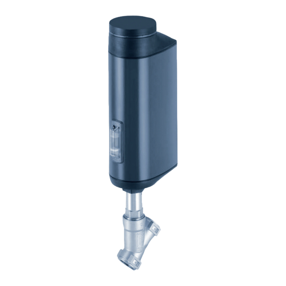
Page 15: Representation - Structure Of The Electromotive Valve
Body connection (with wrench flat) Angle seat valve body Digits for indicating the flow direction Image 2: Assembly, electromotive angle seat valve Type 3320 Blind cover with status indicator and Electrical connectors (cir- bayonet catch cular plug-in connector or cable gland) -
Page 16: Valve Position After Supply Voltage Failure
Types 3320 and 3321 Structure and function Valve position after supply voltage failure Valve position for devices without the SAFEPOS energy-pack energy storage: If the electromotive actuator idles upon a supply voltage failure, the valve remains in the last position that it was in. If the supply voltage fails while the actuator is changing the valve position, the valve remains in an undefined position. -
Page 17: Display Of The Device Status
Types 3320 and 3321 Structure and function Display of the device status The device status is displayed on the LED light ring. Various LED modes can be set to display device status and valve position: • Valve mode • Valve mode + warnings (factory pre-set) •... - Page 18 Types 3320 and 3321 Structure and function 6.4.3 NAMUR operation mode In NAMUR mode the LED light ring lights up in the colour specified for the device status as per NAMUR NE 107. If several device statuses exist simultaneously, the device status with the highest priority is displayed. The priority is based on the severity of the deviation from standard operation (red = failure = highest priority).
-
Page 19: Factory Settings
Types 3320 and 3321 Structure and function 6.4.5 Notifications on device status Notifications on device statuses and errors are entered into the logbook. Chapter “18 Maintenance, trouble- shooting” contains the most common notifications and the measures that they require. Notifications on device status “Function check”... -
Page 20: Control Electronics
Types 3320 and 3321 Control electronics CONTROL ELECTRONICS Function The actuator (stroke) position is controlled by the digital input. The position is specified either by en external signal (analogue) or via a fieldbus (digital). The position sensor records the current position of the electrical linear actuator and from this creates an end position signal via the digital outputs. -
Page 21: Energy Storage Safepos Energy-Pack (Option)
Types 3320 and 3321 Control electronics 7.1.2 Functional diagram External 2 signals for the end controller position signal position Actual position Motor Gear Position sensor Valve (actuator) Image 5: Functional diagram Energy storage SAFEPOS energy-pack (option) The device can also be equipped with the energy storage system (SAFEPOS energy-pack). In the event of a supply voltage failure, the energy storage system supplies the actuator with the energy required to move the valve to the safety position. - Page 22 Types 3320 and 3321 Control electronics NOTE! The energy storage system SAFEPOS energy-pack is a wearing part. The service life figures are appro- ximate values that cannot be guaranteed. 7.2.2 Notifications on the state of the SAFEPOS energy-pack The device issues a warning: The remaining service life of the energy pack is around 25%! The energy pack needs to be replaced soon.
- Page 23 Types 3320 and 3321 Control electronics SAFEPOS energy-pack Safety screw (hexalobular-internal T10) Image 6: Removing SAFEPOS energy-pack Inserting new SAFEPOS energy-pack: → Remove the SAFEPOS energy-pack from the transport packaging. → Insert the SAFEPOS energy-pack into the two guide grooves on the side and push it in until it stops.
-
Page 24: Technical Data
• Maximum permitted operating pressure • Flow direction Conformity The electromotive Type 3320, and 3321 valves are compliant with the EU directives in relation to the EU Decla- ration of Conformity (if applicable). Standards The applied standards, which are used to demonstrate conformity with the directives, are listed in the EU type examination certificate and/or the EU Declaration of Conformity (if applicable). -
Page 25: Operating Conditions
Types 3320 and 3321 Technical data 8.4.1 Additional type label for UL approval (example) Type AE3320 Power Supply LISTED SELV/PELV only! Process control equipment E238179 Image 9: Additional type label for UL approval Operating conditions The product-specific information on the type label must be heeded when operating the device. WARNING! Loss of function if operated below or above permitted temperature range. ▶ Never expose the device to direct sunlight in outdoor areas. - Page 26 Types 3320 and 3321 Technical data 8.5.1 Permitted temperature ranges Minimum temperatures Environment: -25 °C Medium: -10 °C (-40 °C on request) Maximum temperatures Environment: depends on the medium temperature, see subsequent temperature diagram. Medium: depends on the ambient temperature; see temperature diagram below, as well as usage limits of the valve (derating operating pressure).
- Page 27 Types 3320 and 3321 Technical data Derating pressure and temperature ranges Usage limits of the valve (derating operating pressure) Medium temperature Operating pressure -10 – +50 °C 25 bar 100 °C 24.5 bar 150 °C 22.4 bar 200 °C 20.3 bar 230 °C 19 bar Table 6: Derating the operating pressure as per DIN EN 12516-1/PN25...
-
Page 28: General Technical Data
Types 3320 and 3321 Technical data General technical data Dimensions: see data sheet Weight: see data sheet Materials: Actuator: PPS and aluminium, powder-coated valve body: 316L body connection: 316L/1.4401 spindle: 1.4401/1.4404 spindle guide: PEEK packing gland PTFE V-rings with spring compensation (carbon-... - Page 29 Types 3320 and 3321 Technical data Fieldbus gateway: 1 W Energy consumption of actuator for 1 cycle [Ws]* min. 36 Ws max. 140 Ws (depending on device variant and operating conditions) The operating current can be reduced by the following measures, if necessary 1. F or devices with the SAFEPOS energy-pack energy storage: Setting the function “Control if ready” reduces the max. operating current by 1 A. → →...
-
Page 30: Kv Values For Type 3320 And 3321
Kv values for Type 3320 and 3321 Kv value water (m Flow coefficient: Measurement at + 20 °C, 1 bar pressure at the valve inlet and free outlet. 8.8.1 Kv values for angle seat valve Type 3320 Kv value water [m Cv value [gal/min] Seat size... -
Page 31: Installing The Valve
Types 3320 and 3321 Installing the valve INSTALLING THE VALVE Safety instructions WARNING! Risk of injury due to improper installation. ▶ Installation may be carried out by trained technicians only and with the appropriate tools. ▶ Secure the system to prevent unintentional activation. ▶ After installation, ensure that the process is restarted in a controlled manner. Observe the sequence. -
Page 32: Installation Of Devices With Welded Connections
Types 3320 and 3321 Installing the valve 9.2.2 Installation DANGER! Risk of injury from high pressure. ▶ Before working on the system, switch off the pressure and vent or empty the lines. WARNING! Risk of crushing by mechanically powered parts. ▶ Do not reach into the openings of the valve body. - Page 33 Types 3320 and 3321 Installing the valve WARNING! Risk of crushing by mechanically powered parts. ▶ Switch off the supply voltage. ▶ For devices with SAFEPOS energy-packs: Ensure that the SAFEPOS energy-pack is fully discharged. Wait until the LED ring is no longer lit and ensure that the LED status is not in “LED off”...
- Page 34 Types 3320 and 3321 Installing the valve r equired for devices with approval as per EN 161. Filter: According to EN 161 “Automatic shut-off valves for gas burners and gas appliances”, a dirt trap, which prevents the penetration of a 1 mm test pin, must be installed upstream of the valve in the pipeline.
- Page 35 Types 3320 and 3321 Installing the valve → Place on the body connection with a suitable open-end wrench. Do not use any tools for unscrewing that could damage the body connection (e.g. pipe wrench). WARNING! Risk of injury when failing to observe tightening torque value. Failure to observe the tightening torque value is dangerous due to the risk of damage to the device.
-
Page 36: Rotating The Actuator
Types 3320 and 3321 Installing the valve Rotating the actuator The position of the ports can be changed by turning the actuator through 360°. NOTE! Damage to the seat seal and seat contour when valve closed. If the valve is closed when the actuator is turned, the seat seal and the seat contour can be damaged. -
Page 37: Holding Device
Types 3320 and 3321 Installing the valve Holding device The holding device protects the valve actuator from damage resulting from forces and vibrations. The holding device is available as an accessory in 2 sizes. See chapter “22 Accessories, replacement parts”. -
Page 38: Electrical Installation
Types 3320 and 3321 Electrical installation ELECTRICAL INSTALLATION The electromotive valve is available with two connector options: • With a circular plug-in connector (multi-pin variant) • Cable gland with connection terminals Signal values Operating voltage: 24 V Digital input for position signal: 0...5 V = log “0”; 10...30 V = log “1”... - Page 39 Types 3320 and 3321 Electrical installation 10.1.2 Description of circular plug-in connectors X3 – M12 circular plug, 5-pin Operating voltage X1 – M12 circular plug, 8-pin Input and output signals FE Functional earth Image 15: Description of circular plug-in connectors 10.1.3 X1 – M12 circular plug, 8-pin Wire colour* Layout (from device perspective) Input signals from control centre (e.g. PLC) 0...5 V (log.
- Page 40 Types 3320 and 3321 Electrical installation 10.1.4 X3 – M12 circular plug, 4-pin or 5-pin, operating voltage Wire colour without büS with büS Layout (from device perspective) network network 4-pin connection* CAN shield 24 V ± 10% white max. residual ripple 10% Blue Black GND/CAN_GND white...
-
Page 41: Electrical Installation With Cable Gland
Types 3320 and 3321 Electrical installation 10.2 Electrical installation with cable gland 10.2.1 Safety instructions WARNING! Risk of injury due to improper installation. ▶ Installation may be carried out by authorised technicians only and with the appropriate tools. ▶ Observe general engineering standards & rules during installation. - Page 42 Types 3320 and 3321 Electrical installation 2. Remove the LED and storage module: → Remove the 2 fastening screws (Allen key, width across flats 3 mm). → Grab the LED and storage module by both sides of the metal housing and lift it out. Removing actuator cover:...
- Page 43 Types 3320 and 3321 Electrical installation NOTE! The ingress of dirt or moisture may cause damage or malfunction. To preserve IP65 protection, ensure the following: ▶ Unused cable glands must be sealed using dummy plugs. ▶ The union nuts of cable glands must be tightened. Tightening torque, dependent on the cable size or dummy plugs, approx.
- Page 44 Types 3320 and 3321 Electrical installation 10.2.4 Terminal layout – input signal from control centre (e.g. PLC) Clip Layout (from device perspective) 0...5 V (log. 0) Digital input + 10...30 V (log. 1) Digital input, GND relates to GND operating voltage (GND Clip)
- Page 45 Types 3320 and 3321 Electrical installation 10.2.6 Close device NOTE! The ingress of dirt or moisture may cause damage or malfunction. To preserve IP65 protection, ensure the following before closing the device: ▶ The seal in the actuator housing/actuator cover must be inserted and undamaged. ▶ The seal surfaces must be clean and dry.
- Page 46 Types 3320 and 3321 Electrical installation → Place the LED and storage module onto the actuator cover. Align the recess for the manual override in the centre, paying attention to the correct alignment of the electrical plug connection. → Carefully press down the LED and storage module by hand.
-
Page 47: Start-Up
Types 3320 and 3321 Start-up START-UP 11.1 Safety instructions WARNING! Risk of injury due to improper operation. Improper operation may result in injuries as well as damage to the device and the surrounding area. ▶ The operating personnel must know and understand the contents of the operating instructions. -
Page 48: Adjustment Of Position Controller - Execute X.tune
Types 3320 and 3321 Start-up 11.4 Adjustment of position controller – execute X.TUNE When executing the X.TUNE function the position control is adjusted at the physical stroke of the electro- motive actuator in use. Devices come with the X.TUNE function performed by the manufacturer. NOTE! Only perform X.TUNE if absolutely necessary. The X.TUNE function only has to be executed again if the actuator has been dismantled or the valve body has been replaced. - Page 49 Types 3320 and 3321 Start-up 11.4.2 Adjustment of position control on PC Settings are created on the PC using the büS service interface and the Bürkert Communicator PC software. It requires the USB büS interface set available as an accessory.
-
Page 50: Set Automatic Operating State
Types 3320 and 3321 Start-up 11.5 Set AUTOMATIC operating state Set AUTOMATIC operating state: → Set DIP switch 4 to AUTOMATIC. DIP switch AUTOMATIC operating state: DIP 4 down Image 22: Set AUTOMATIC operating state English... -
Page 51: Operation
Types 3320 and 3321 Operation OPERATION WARNING! Risk of injury from improper operation. Improper operation may result in injuries as well as damage to the device and its surroundings. ▶ The operating personnel must know and understand the contents of the operating instructions. ▶ The safety instructions must be followed and the device used only as intended. -
Page 52: Display Elements
Types 3320 and 3321 Operation 12.2 Display elements Description of the display elements: LED illuminated ring Mechanical position 4 different, adjustable indicator LED modes Valve opened Valve closed Image 23: Display elements 12.2.1 LED illuminated ring The transparent LED illuminated ring that transmits the light of the LEDs to the outside is fitted to the blind cover. -
Page 53: Operating Elements
Types 3320 and 3321 Operation 12.3 Operating elements Presentation of the operating elements: SIM card büS service interface DIP switch CLOSE button OPEN button Mechanical manual override Image 24: Operating elements 12.3.1 DIP switch Settings Switch 1: Enable or disable safety position (see chapter “13.2” on page 59). -
Page 54: Büs Service Interface
Types 3320 and 3321 Operation 12.4 büS service interface The büS service interface can be used for quick service. • Configuration of the device, e.g. the base setting for start-up with the PC software Bürkert Communicator. It requires the USB büS interface set available as an accessory. -
Page 55: Sim Card - Acquire And Save Data (Option)
Types 3320 and 3321 Operation 12.5 SIM card – acquire and save data (option) The optional SIM card can be used to store device-specific values and user settings and transfer them to another device. The SIM card is detected when the device starts and is checked for available data. This data will be transferred or overwritten accordingly: •... -
Page 56: User Interface Of The Bürkert Communicator Pc Software
Types 3320 and 3321 Operation 12.6 User interface of the Bürkert Communicator PC software Configuration area view: Navigation area Menu bar Add interface (Connect with büS stick) COMMUNICATOR File Edit View Options Tools Device Help Positioner Home page Parameters Diagnostics Maintenance Desktop... -
Page 57: Establish The Connection Between Device And Bürkert Communicator
Types 3320 and 3321 Operation View of the application area: Current user level COMMUNICATOR File Edit View Options Tools Device Help 0031321000000001 E_Process_Valve 3320 Home page Positioner Desktop 73.7% Graph büS Inputs/outputs 0031321000000001 E_Process_Valve 3320 Positioner Inputs/outputs General settings Zoom 100% Overview: Configuration areas of the... -
Page 58: Basic Functions
Types 3320 and 3321 Basic functions BASIC FUNCTIONS The basic functions are set using the DIP switch position. DIP switch Basic function Enable or disable safety position DIP switch Set safety position and effective direction (NC and NO) Not used Switch between AUTOMATIC and MANUAL operating state. -
Page 59: Set Safety Position And Effective Direction
Types 3320 and 3321 Basic functions 13.2 Set safety position and effective direction The effective direction and safety position are set using DIP switches 1 and 2. DIP switch 2 DIP switch 1 Switch position Set-point value Effective Switch position Safety position (safety position (0...5 V) (10...30 V) -
Page 60: Advanced Functions
Types 3320 and 3321 Basic functions ADVANCED FUNCTIONS X.TIME – limitation of control speed 14.1 This auxiliary function can be used to set the opening and closing times for the entire stroke, and thus limit the control speeds. When performing the X.TUNE function, the minimum opening and closing time are entered for the entire stroke for Open and Close. -
Page 61: X.limit - Mechanical Stroke Range Limit
Types 3320 and 3321 Basic functions → Enter and confirm the lower limit value. → Select Closing time. → Enter and confirm the upper limit value. You have enabled and configured the control time limit. 14.2 X.LIMIT – mechanical stroke range limit This auxiliary function limits the (physical) stroke to defined per cent values (minimum and maximum). -
Page 62: Set Led Operation Mode
Types 3320 and 3321 Basic functions How to enable the mechanical stroke limit: → Select ADD.FUNCTION. → Select X.LIMIT. The mechanical stroke limit is enabled and the menu X.LIMIT for configuration is now available. How to configure the mechanical stroke limit: → Select X.LIMIT in the detailed view “Parameter”. → Select Maximum. →... -
Page 63: Setting The Colours For Indicating Valve Position
Types 3320 and 3321 Basic functions 14.4 Setting the colours for indicating valve position The colours on the LED light ring that indicate the valve positions can be set individually. Configuration using the Bürkert Communicator software on PC: The Bürkert Communicator PC software can be downloaded free of charge from the Bürkert website. It requires the USB büS interface set available as an accessory. Communication is performed via the device’s büS service interface. The setting is made in the detailed view “Parameter for general settings”. -
Page 64: Manual Override Of Valve
Types 3320 and 3321 Manual override of valve MANUAL OVERRIDE OF VALVE The actuation of the valve can be manually overridden by electrical or mechanical means. Electrical manual override is usually used to manually open and close the valve. The valve must be opened and closed via mechanical manual override if there is a power failure. The valve must only be manually overridden while in a de-energised state. -
Page 65: Actuating The Valve Mechanically
Types 3320 and 3321 Manual override of valve 15.2 Actuating the valve mechanically If there is no supply voltage, e.g. during installation or in the event of a power failure, the valve can be opened or closed using the mechanical manual override. - Page 66 Types 3320 and 3321 Manual override of valve → Apply light pressure to lock the mechanical manual override mechanism into place while turning the Allen key at the same time (see “Image 35”). → Move the valve to the desired position.
-
Page 67: Operating Structure And Factory Setting
Types 3320 and 3321 Operating structure and factory setting OPERATING STRUCTURE AND FACTORY SETTING The factory default settings are depicted in blue in the operating structure to the right of the menu. Examples: Factory-enabled or selected menu options Factory-disabled or unselected menu options sec, ... - Page 68 Types 3320 and 3321 Operating structure and factory setting Positioner MAINTENANCE CALIBRATION X.TUNE Image 38: Operating structure – 1-b, positioner maintenance Positioner DIAGNOSTICS SYSTEM.VALUES Operation time Travel accumulator Direction change Device temperature Highest temperature Lowest temperature HISTOGRAM.POS HISTOGRAM.SPAN HISTOGRAM.DTEMP ENERGY-PACK...
- Page 69 Types 3320 and 3321 Operating structure and factory setting Positioner DIAGNOSTICS USER.DIAGNOSIS ADD.DIAGNOSE SERVICE.TIME TRAVEL.ACCU CYCLE.COUNTER POS.MONITOR HISTOGRAM.POS HISTOGRAM.SPAN SERVICE.TIME Operation time Interval Next message TRAVEL.ACCU Travel accumulator Interval Next message CYCLE.COUNTER Direction change Interval Next message POS.MONITOR Tolerance band...
- Page 70 Types 3320 and 3321 Operating structure and factory setting Inputs/ outputs PARAMETERS Digital CMD.source büS CANopen Fieldbus ADDITIONAL IOs DIGITAL OUT 1 FUNCTION Position limit DIGITAL OUT 2 Device state Manual mode Safepos Position limit Device state Maintenance Out of specification...
- Page 71 Types 3320 and 3321 Operating structure and factory setting General settings PARAMETERS Operation mode Status LED NAMUR operation mode Valve mode Valve mode + warnings LED off Yellow Valve open Green Valve closed Green Valve in between büS Displayed name...
- Page 72 Types 3320 and 3321 Operating structure and factory setting General settings PARAMETERS Diagnostics PDO configuration PDO 1 PDO 2 PDO 3 Multiplexed PDO Reset to default values Image 43: Operating structure – 3-b, configuration area “General settings” General settings MAINTENANCE Device information Displayed name...
- Page 73 Types 3320 and 3321 Operating structure and factory setting General settings DIAGNOSTICS Device status Operating duration Device temperature Supply voltage Min./max. values Max. temperature Removable storage status Min. temperature Max. supply voltage Min. supply voltage büS status Receive errors Receive errors max.
-
Page 74: Industrial Ethernet
Types 3320 and 3321 Industrial Ethernet INDUSTRIAL ETHERNET To allow connection to an Ethernet network, the electromotive control valve with integrated fieldbus gateway is optionally available. Supported fieldbus protocols: Ethernet/IP, PROFINET, Modbus TCP. 17.1 Fieldbus gateway description Fieldbus gateway Fieldbus connector M12 (2-port Ethernet switch) - Page 75 Types 3320 and 3321 Industrial Ethernet 17.1.2 LEDs for indicating network connection status The LEDs for indicating network connection status are located inside the fieldbus gateway. To access it, turn the cover counterclockwise. Interfaces X1 and X2 2-port Ethernet switch...
-
Page 76: Technical Data Industrial Ethernet
Types 3320 and 3321 Industrial Ethernet 17.2 Technical data Industrial Ethernet 17.2.1 PROFINET IO specifications Topology recognition LLDP, SNMP V1, MIB2, Physical Device Minimum cycle time 10 ms not supported MRP media redundancy MRP client is supported Other supported functions DCP, VLAN Priority Tagging, Shared Device Transmission speed 100 MBit/s... -
Page 77: Projecting Via Fieldbus
Types 3320 and 3321 Industrial Ethernet 17.3 Projecting via fieldbus For project planning, you need the suitable start-up file for the respective fieldbus protocol. Fieldbus Start-up file EtherNet/IP EDS file PROFINET GSDML file Modbus TCP not required The start-up files required for the respective project planning software and their description are available on the Internet. - Page 78 Types 3320 and 3321 Industrial Ethernet • Factory default setting: 255.255.255.0 Network mask • Standard gateway Factory default setting: 192.168.0.1. With PROFINET, the factory default setting for the standard gateway is 0.0.0.0. Setting for EtherNet/IP fieldbus protocol: → Select IP settings. → Select IP operation mode and set the desired operation mode. Factory default setting: Fixed IP address. You have set the Ethernet parameters to connect the device to the PLC network.
-
Page 79: Web Server
Types 3320 and 3321 Industrial Ethernet 17.4 Web server The configuration of the Ethernet participant, required to connect to the network, can be run with a web server. 17.4.1 Connecting to the web server → Only with PROFINET: Assign IP addresses and DNS-compatible name with a suitable start-up tool for PROFINET attachments. - Page 80 Types 3320 and 3321 Industrial Ethernet With EtherNet/IP, DHCP or BOOTP can also be set (NOT by default). In this process, the IP address is acquired from a DHCP server. → Open an internet browser. → Enter default IP 192.168.0.100.
-
Page 81: Advanced Functionalities
Types 3320 and 3321 Industrial Ethernet Configuration: → Enter the device name and IP address for the Ethernet participant. The device name assigned here is used later during project planning (e.g. under STEP 7). → Confirm with Commit changes. → Conduct a power reset of the Ethernet participant to incorporate the changed parameters. - Page 82 Types 3320 and 3321 Industrial Ethernet 17.5.2 Device Status NAMUR NE 107 Name Description Access type Device status Corresponds to device status of Type 3323, 3324, 3325 NAMUR NE 107 Bit 7 Bit 6 Bit 5 Bit 4 Bit 3 Bit 2...
-
Page 83: Maintenance, Troubleshooting
Types 3320 and 3321 Maintenance, troubleshooting MAINTENANCE, TROUBLESHOOTING 18.1 Safety instructions DANGER! Risk of injury from high pressure in the device or system. ▶ Switch off the pressure before working on the device or system. Vent or empty the lines. Risk of injury due to electric shock. ▶ Before working on the device or system, switch off the power supply. Secure it against reactivation. - Page 84 Types 3320 and 3321 Maintenance, troubleshooting 18.2.3 Visual inspection According to the usage conditions, perform regular visual inspections: → Check medium ports for tightness. → Check relief bore on the pipe for leaks. Relief bore Image 52: Relief bore 18.2.4 Replacing the energy storage SAFEPOS energy-pack Replacement of the SAFEPOS energy-pack is described in chapter “7.2.3 Replacing the SAFEPOS...
-
Page 85: Troubleshooting
Types 3320 and 3321 Maintenance, troubleshooting 18.3 Troubleshooting 18.3.1 Notifications on device status “Out of specification” Notifications on device status “Out of specification” are displayed in the following LED operation modes: • Valve mode + warnings (factory pre-set). The LED light ring alternatingly flashes yellow and the colour indicating the valve position. - Page 86 Types 3320 and 3321 Maintenance, troubleshooting 18.3.2 Error notifications Device error notifications are displayed as follows: • Valve mode The LED light ring alternatingly flashes red and the colour indicating the valve position. • Valve mode + warnings (factory pre-set).
- Page 87 Types 3320 and 3321 Maintenance, troubleshooting Notification Description Device behaviour Measure Internal error: Rever- Signal failure of the Error notification. Contact Bürkert service. beration sensor signal position sensor. Actuator is moving to failure. safety position. MANUAL operating state not possible. Internal error: ...
-
Page 88: Canopen
Types 3320 and 3321 CANopen CANopen For electrical installation of devices with CANopen network: refer to chapter “20.1 Cabling of büS networks” on page 88 for description. 19.1 Projecting via fieldbus For project planning, you need an eds file as a start-up file for CANopen. The eds file and the associated description are available on the Internet. Download at: www.burkert.com / Type 3360, 3361 / Downloads “Software” / Initiation Files Please refer to the documentation of your project design software for instructions regarding the installation of the start-up files. -
Page 89: Cleaning
Types 3320 and 3321 Cleaning CLEANING The use of alkaline cleaning agents is not permitted for cleaning the surface of the device. English... -
Page 90: Accessories, Replacement Parts
Types 3320 and 3321 Accessories, replacement parts ACCESSORIES, REPLACEMENT PARTS CAUTION! Risk of injury and/or damage due to incorrect parts. Incorrect accessories and unsuitable spare parts may cause injuries and damage the device and the area around it. ▶ Use only original accessories and original spare parts from Bürkert. -
Page 91: Spare Parts
To communicate with the devices the PC requires a USB interface and the USB büS interface set available as an accessory (see “Table 28: Accessories”). 22.2 Spare parts 22.2.1 Spare parts for valves of Types 3320 and 3321 Spare parts for Type 3320 and 3321 Order number SAFEPOS energy-pack 285834... -
Page 92: Assembly Tools
262157 262170 262174 262177 262179 Table 32: Valve seat set for Type 3321 22.3 Assembly tools 22.3.1 Installation tools for valves of Types 3320 and 3321 Modified socket wrench for packing gland (series-production status as of April 2012) Spindle ø [mm] Body DN Width across flats Order number 15...40 SW16 683221... -
Page 93: Disassembly
Types 3320 and 3321 Accessories, replacement parts DISASSEMBLY 23.1 Safety instructions DANGER! Risk of injury due to high pressure and escaping medium. If the device is pressurised while being disassembled, there is a risk of injury due to sudden depressuri- sation and medium discharge. ▶ Turn off the pressure before dismantling the device. Vent or empty the lines. -
Page 94: Packaging And Transport
Types 3320 and 3321 Packaging and Transport PACKAGING AND TRANSPORT CAUTION! Risk of injury due to heavy device. During transportation or installation work, the device may fall down and cause injuries. ▶ Transport, install and remove heavy device with the aid of a second person only. - Page 95 Types 3320 and 3321 English...
- Page 96 www.burkert.com...
Need help?
Do you have a question about the 3320 and is the answer not in the manual?
Questions and answers