Sign In
Upload
Manuals
Brands
Burkert Manuals
Control Unit
AirLINE 8652 Series
Burkert AirLINE 8652 Series Manuals
Manuals and User Guides for Burkert AirLINE 8652 Series. We have
1
Burkert AirLINE 8652 Series manual available for free PDF download: Operating Instructions Manual
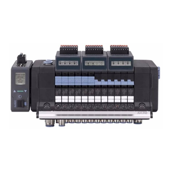
Burkert AirLINE 8652 Series Operating Instructions Manual (122 pages)
Modular valve island for pneumatic
Brand:
Burkert
| Category:
Control Unit
| Size: 12.54 MB
Table of Contents
Table of Contents
3
Operating Instructions
6
Symbols
6
Definition of Terms
7
Intended Use
8
Basic Safety Instructions
9
General Notes
11
Contact Address
11
Warranty
11
Information on the Internet
11
Product Description
12
Product Structure
13
External Safety-Related Shutdown of Valves
16
Technical Data
17
Standards and Directives
17
Operating Conditions
17
Pneumatic Data
17
General Electrical Data
18
Electrical Data of Electronic Module with Digital Inputs
19
Pneumatic Slide Valve Type 6534
20
Circuit Function (CF)
21
Standard Type Label (Example)
22
Type Label UL (Example)
22
Industrial Ethernet Specifications
23
Specifications Profibus Dpv1
25
CC-Link Specifications
25
Installation of the Valve Island in the Control Cabinet
26
Installation on the Control Cabinet Floor or the Control Cabinet Wall with Airline Quick
27
Standard Rail Installation
30
Electrical Connection
32
Cabling of Büs Networks
32
Fieldbus Gateway ME43
32
Supply Voltage for Pneumatic Valves
36
Electronic Module with Digital Inputs (Optional)
37
Electrical Connection Assignment
38
Valves Type 6534 for Safety-Related Shutdown, Variant SIA (Optional)
39
Modular Safety-Related Shutdown (Optional)
41
Pneumatic Connection
43
Assignment of the Pneumatic Ports
43
Pneumatic Connection Assignment
45
Integration into the Control Environment
46
Start-Up Files And Description Of The Process Data And Parameters
46
Plc Compatibility
46
Commissioning A Profinet Device With Siemens Tia Portal
48
Commissioning A Profibus Dpv1 Device With Siemens Tia Portal
51
Commissioning An Ethernet/Ip Device With Rockwell Logix Designer
54
Bit-Wise Composition Of The Inputs And Outputs
57
Advanced Gateway Functionalities
57
Configuration with Web Server
58
Establishing A Connection To The Web Server
58
Logging Onto The Web Server
59
Passwords
59
Finding The Device
59
Disabling Web Server Access With Bürkert Communicator
60
Information In The Web Server
60
Setting Options In The Web Server
60
Industrial Communication Of Web Server
61
Configuration with Fieldbus Gateway
62
Operating The Fieldbus Gateway
62
Selecting The Protocol
62
Enter Profibus Address Or CC-Link Address
63
Converting Compatibility Mode
63
Valve Configuration
63
Configure Pressure Sensor(S)
63
Display: Contrast, Brightness, Installation Position, Language
64
Configuration Provider
64
Error Diagnostics
64
Restarting The Valve Island
64
Factory Reset
64
Reset The Switching Cycle Counters
65
Replacing Devices (Config Clients)
65
Menu Structure Fieldbus Gateway
66
Fieldbus Gateway Display Elements
68
Leds For Indicating The Network Connection To Industrial Ethernet
68
Led For Displaying The Device Status
69
15 Bürkert Communicator Basics
70
User Levels
71
Connecting The Device To The Bürkert Communicator
72
Configuration with Bürkert Communicator
73
Base Valve Island Settings
73
Base Industrial Communicator Settings
73
Base Settings Canopen/Büs
75
Reset Device To Factory Settings
75
Restart Device
75
Switch Time Monitoring Of Actuators
75
Disabling Access To Web Server
75
Using Extension Modules (Em)
76
Bürkert Communicator Menu Structure
78
Start-Up
83
Safety Instructions
83
Commissioning Via Manual Override
83
Identification Of The Valve Positions
84
Displays
85
Description Of Displays
85
Combine Valve Island with External DI Modules
88
Assign Position Feedback Sensor Source In The Automation Software
88
Assign Position Feedback Sensor Source In Bürkert Communicator
88
Network Configuration In The Bürkert Communicator
89
Show Errors From Büs Partners On The Display
93
Configure External DI Modules Using A Wizard
94
Switch Time Monitoring Function
95
What Exactly Is Being Measured
95
Settings For The Actuator Switching Time
95
Start Switching Time Measurement
96
Error Messages For The Function Of The Switching Time Monitoring
97
Micro Sd Card
98
Backup Battery
100
Replacing Spare Parts
101
Connection Module Without Pressure Sensor
101
Connection Module With Pressure Sensor
103
Electronic Module
105
Pneumatic Valves
106
Replace the Me43 Fieldbus Gateway
110
Maintenance, Troubleshooting
111
Safety Instructions
111
Replace Filter For Auxiliary Pilot Air
111
Troubleshooting
112
Error Messages On The Lc Display Of The Electronic Modules
113
Description Of The Error Code
114
Disassembly
118
Safety Instructions
118
Accessories
119
Packaging and Transport
122
Storage
122
Environmentally Friendly Disposal
122
Advertisement
Advertisement
Related Products
Burkert AE3360
Burkert AE3365
Burkert AE3363
Burkert AE3364
Burkert AE3320
Burkert AE3323
Burkert AE3324
Burkert AE3325
Burkert PTB 00 ATEX 2129 X
Burkert ACP016 Series
Burkert Categories
Control Unit
Controller
Measuring Instruments
Transmitter
Accessories
More Burkert Manuals
Login
Sign In
OR
Sign in with Facebook
Sign in with Google
Upload manual
Upload from disk
Upload from URL