
Related Manuals for FISCHER PRO-LINE DE90


Summary of Contents for FISCHER PRO-LINE DE90
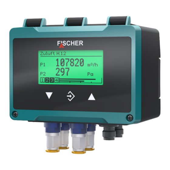
- Page 1 II 3G Ex nA IIC T4 Gc II 3D Ex tc IIIB T125°C Dc Operating manual DE90 Differential pressure transmitter PRO-LINE ®...
- Page 2 Great care was taken when compiling the texts and illustrations; Nevertheless, errors cannot be ruled out. The company FISCHER Mess- und Regeltechnik GmbH will not accept any legal responsibility or liability for this.
-
Page 3: Table Of Contents
FISCHER Mess- und Regeltechnik GmbH Table of Content Table of Content 1 Safety instructions ......................6 1.1 General........................... 1.2 Personnel Qualification......................1.3 Risks due to Non-Observance of Safety Instructions ............. 1.4 Safety Instructions for the Operating Company and the Operator ......... - Page 4 Table of Content FISCHER Mess- und Regeltechnik GmbH 4.3 Setup ............................25 4.3.1 Set menu language........................25 4.3.2 Measuring point designation ...................... 25 4.3.3 Configuration..........................25 4.4 Modbus RTU interface......................25 5 Operation.......................... 26 5.1 First steps ..........................26 5.1.1 Operating modes ........................26 5.1.2 Menu tree...........................
- Page 5 FISCHER Mess- und Regeltechnik GmbH Table of Content 5.5.6.7 LCD contrast..........................88 5.5.7 Modbus RTU..........................89 5.5.7.1 Baud rate ............................ 90 5.5.7.2 Data format..........................90 5.5.7.3 Modbus address ......................... 91 5.5.7.4 Byte order ........................... 91 5.6 Info............................92 5.7 Service............................ 93 6 Servicing...........................
-
Page 6: Safety Instructions
1 | Safety instructions FISCHER Mess- und Regeltechnik GmbH 1 Safety instructions 1.1 General This operating manual is an integral part of the product and therefore needs to be kept close to the instrument in a place that is accessible at all times to the re- sponsible personnel. -
Page 7: Unauthorised Modification
FISCHER Mess- und Regeltechnik GmbH Safety instructions | 1 1.5 Unauthorised Modification Modifications of or other technical alterations to the instrument by the customer are not permitted. This also applies to replacement parts. Only the manufacturer is authorised to make any modifications or changes. - Page 8 1 | Safety instructions FISCHER Mess- und Regeltechnik GmbH Other symbols This table explains how the different objects (menu, parameters, etc.) are shown in these operating instructions. Symbol Description This symbol indicates that the switch output con- tact is open.
-
Page 9: Product And Functional Description
FISCHER Mess- und Regeltechnik GmbH Product and functional description | 2 2 Product and functional description 2.1 Delivery scope ® • Differential pressure transmitter DE90 PRO-LINE version as stated on the type plate with an integrated assembly rail. Attach- ment screws are not included in the delivery. -
Page 10: Function Diagram
2 | Product and functional description FISCHER Mess- und Regeltechnik GmbH 2.3 Function diagram Display Power supply 24 V AC/DC þ û ÿ Sensor 1 Channel 1 Analogue output 1 Differential pressure Switch output 1 Switch output 2 µC Switch output 3... -
Page 11: Equipment Versions
FISCHER Mess- und Regeltechnik GmbH Product and functional description | 2 2.5 Equipment versions Process connections The presented connections are used for all models. Model: 1-channel 2-channel Pneumatics Plug connection CK screw connection Cutting ring connection Fig. 2: Process connections Electrical connections Two M12 flange connectors are used for the electrical connection. -
Page 12: Type Plate
2 | Product and functional description FISCHER Mess- und Regeltechnik GmbH 2.5.1 Type plate The type plates presented here serve to show an example of the information shown. Some information may not be required depending on the specific device model. -
Page 13: Assembly
FISCHER Mess- und Regeltechnik GmbH Assembly | 3 3 Assembly 3.1 General The device is designed for installation onto assembly plates or flat walls. To this end, a pre-mounted 35 mm plastic mounting rail is also supplied. The attach- ment screws are not included in the delivery. -
Page 14: Replacement Plates
3 | Assembly FISCHER Mess- und Regeltechnik GmbH 1. Differential pressure measurement Higher pressure lower pressure 2. Pressure measurement Pressure open 3.3.1 Replacement plates Depending on the number of measuring channels, the device is equipped with various replacement plates. Channel 1... -
Page 15: Cutting Ring Screw Connections
FISCHER Mess- und Regeltechnik GmbH Assembly | 3 3.3.2 Cutting ring screw connections w In the case of cutting ring screw connections, incorrect installation of the pressure lines can lead to a destruction of the replacement plate due to the acting forces. -
Page 16: Devices With Switch Outputs
3 | Assembly FISCHER Mess- und Regeltechnik GmbH The earthing connection serves to discharge static electricity. Earth terminal Warning WARNING - DO NOT CONNECT OR DISCONNECT EQUIPMENT UNDER VOLTAGE Fig. 10: Ground connection 3.4.2 Devices with switch outputs 3.4.2.1 3-conductor circuit The device is connected as follows in a 3-wire switch as described below. -
Page 17: M12 Connector 1: Auxiliary Energy And Analogue Output
FISCHER Mess- und Regeltechnik GmbH Assembly | 3 3.4.2.2 M12 connector 1: auxiliary energy and analogue output 1 channel version PIN Signal Cable colour 1 Operating voltage Brown 2 Analog output 1 -AOut1 White 3 Operating voltage Blue 4 Analog output 1... -
Page 18: Device With Modbus
3 | Assembly FISCHER Mess- und Regeltechnik GmbH 3.4.3 Device with Modbus DANGER Auxiliary for ATEX devices When selecting the power supply, bear in mind that it may be a potential ignition source. Take suitable safety precautions to prevent this risk. -
Page 19: Auxiliary Energy Supply
FISCHER Mess- und Regeltechnik GmbH Assembly | 3 3.4.3.2 Auxiliary energy supply The following illustrations explain the principle of the power supply of the DE90 in the Modbus network. However the feeder nodes are not part of the delivery scope and need to be installed by the operator himself. -
Page 20: M12 Plug 2: Modbus Out
3 | Assembly FISCHER Mess- und Regeltechnik GmbH 3.4.3.4 M12 plug 2: Modbus OUT PIN Signal Cable colour 1 Operating voltage Brown 2 Modbus BUS-D1 White 3 Operating voltage Blue 4 Modbus BUS-D0 Black 5 Modbus BUS-R Grey A Coding Fig. 23: M12 bush 5-pin... -
Page 21: Start-Up
FISCHER Mess- und Regeltechnik GmbH Start-up | 4 4 Start-up NOTICE! If operated in explosive areas, the checks carried out in line with the valid local regulations and guidelines for the installation and operation of electrical systems in explosive areas must be carried out. -
Page 22: Measured Value Display
4 | Start-up FISCHER Mess- und Regeltechnik GmbH 4.2.1 Measured value display Depending on the unit model, there are different presentation variants for the measured value display. 4.2.1.1 1 channel version Measured value display Designation Measurement point 1 P a 2 9.07... -
Page 23: Channel Version
FISCHER Mess- und Regeltechnik GmbH Start-up | 4 4.2.1.3 3 channel version The 3-channel display is only available for the 'Difference' and 'Dynamic filter monitoring' functions. Channel 3 is a so-called virtual channel '. The displayed value is calculated from the measured values of channels 1 and 2. -
Page 24: Keyboard
4 | Start-up FISCHER Mess- und Regeltechnik GmbH 4.2.2 Keyboard The basic functions of the keyboard are explained in this section. For more in- formation about the operating concept, please see the section 'first steps'. Measurement point 1 P a 2 9.07 Fig. 29: Operating keys... -
Page 25: Setup
FISCHER Mess- und Regeltechnik GmbH Start-up | 4 4.3 Setup The measuring device is delivered in the configuration stated in the Order code [} 101]. However, some parameters can be modified quickly and easily via the menu Quick access [} 41]. • Menu language •... -
Page 26: Operation
5 | Operation FISCHER Mess- und Regeltechnik GmbH 5 Operation 5.1 First steps 5.1.1 Operating modes Operating mode After activation, the device automatically starts. The device works according to its configuration. Configuration mode Pressing the button û takes the user from the operating mode to the configur- ation mode. - Page 27 FISCHER Mess- und Regeltechnik GmbH Operation | 5 Menu tree Parameterization Config. Channel 1 Channel 1 Mode C1 Menu expansion Mode C1 Flow rate Characteristic C1 Measurement C1 Displ.range C1 unit Meas.range C1 unit Displ.range C1 start Meas.range C1 start Displ.range C1 end...
- Page 28 5 | Operation FISCHER Mess- und Regeltechnik GmbH Analog output Analogue output An.output 1 type An.output 1 assignmt An.output 2 type An.output 2 assignmt Limit I min. Limit I max. I fault Limit U min. Limit U max. U fault Switch output Config.
-
Page 29: Navigation In The Menu Tree
FISCHER Mess- und Regeltechnik GmbH Operation | 5 5.1.3 Navigation in the menu tree Pressing the button û takes the user from the measured value display to the main menu. Measurement point 1 P a 5 98.99 û P a 2 9.07... - Page 30 5 | Operation FISCHER Mess- und Regeltechnik GmbH Level 0 Login û Quick access Configuration Info Level 1 Quick access Language Menu Designation Parameter Meas.range C1 unit Menu Measuring range C1 start Parameter Fig. 34: Sidewards in submenu (Level 1) Back To leave the menu, the cursor needs to be moved to the menu item Pressing this button û...
-
Page 31: Directory Details
FISCHER Mess- und Regeltechnik GmbH Operation | 5 5.1.4 Directory details The path information appears in the first line of the display. For space reasons, the directories cannot be shown in full. The menu level is indicated by the num- ber if backslash symbols ‚\‘. -
Page 32: Value Input
5 | Operation FISCHER Mess- und Regeltechnik GmbH Cursor Select field \...\Designation û easuring point M N O P Q R D Symbol list Fig. 38: Editing text In this display, the cursor is controlled with the button û . The cursor can only be moved right. - Page 33 FISCHER Mess- und Regeltechnik GmbH Operation | 5 Ms.range C1 start û 020.000 -100.000 100.000 Movement direction of the cursor û Ms.range C1 start 020.000 Edit Cancel Fig. 41: Input of number values 2nd place The button repeat û automatically returns the user to the action selection.
-
Page 34: Selection Of Options
5 | Operation FISCHER Mess- und Regeltechnik GmbH 5.1.5.3 Selection of options For example: Directory: \ Configuration \ Channel 2\ Measurement C2\ Meas.range C2 unit Meas.range C2 unit ÿ mbar Ms.range C2 unit û mbar Fig. 43: Entry of options The cursor is moved with the buttons ÿ and þ . Only one of the offered op- tions can be selected. -
Page 35: Main Menu
FISCHER Mess- und Regeltechnik GmbH Operation | 5 5.2 Main menu Directory: \ Level: 0 Pressing the button û takes the user from the operating mode to the configur- ation mode. The main menu is displayed. Bargraph display and display of the switch outputs still remain visible. -
Page 36: Login
5 | Operation FISCHER Mess- und Regeltechnik GmbH 5.3 Login Directory: \Login Level: 1 Users that are not logged on only have access to the information menu. Users must log in to gain access to the configuration. \Login Log in... -
Page 37: Log In / Log Out
FISCHER Mess- und Regeltechnik GmbH Operation | 5 5.3.1 Log in / log out Directory:\Login\ Log in Level: 2 Login is realised by entering a number. After entering the correct password, the menus to which the users have access rights are unlocked. -
Page 38: Timeout
5 | Operation FISCHER Mess- und Regeltechnik GmbH 5.3.2 Timeout Directory: \Login\Timeout Level: 2 If the device is switched to configuration mode and no button is pressed, the device returns to the operating mode after the expiry of a defined time period. -
Page 39: User 1
FISCHER Mess- und Regeltechnik GmbH Operation | 5 5.3.3.1 User 1 Directory: \Login\ Manage users \ User 1 Level: 3 \...\...\User 1 User 1 enabled User 1 password User 1 permissions Back Fig. 49: User 1 Menu name Description User 1 enabled The user can be enabled with this parameter. -
Page 40: Administrator
5 | Operation FISCHER Mess- und Regeltechnik GmbH View configuration The parameter is used to define whether the user may read the configuration. Activation of the reading rights is indicated with the symbol of a crossed-out pencil. This should display the missing writing rights. -
Page 41: Reset Passwords
FISCHER Mess- und Regeltechnik GmbH Operation | 5 5.3.4 Reset passwords Directory: \Login\ Reset passwords Level: 2 \Login Log out Timeout û Manage user Log out Set passwords to default values? û Cancel Fig. 52: Reset passwords All passwords are set to the default value 000. Only the administrator can carry out this action. - Page 42 5 | Operation FISCHER Mess- und Regeltechnik GmbH Menu name Description Meas.range C1 end The end of the measuring range of the 1st measuring channel is defined with this parameter. Damping C1 This parameter can be used to set a damping for the 1st measuring chan- nel.
-
Page 43: Configuration
FISCHER Mess- und Regeltechnik GmbH Operation | 5 5.5 Configuration With the inTouch® software, parameterization can also be carried out on the PC. The finished parameter set is then transferred to the DE90 via the USB in- terface. WARNING Parameterization in hazardous areas The housing must not be opened within the ATEX area. - Page 44 5 | Operation FISCHER Mess- und Regeltechnik GmbH Signpost [►Page] • Channel 1 [} 45] • Channel 2 [} 67] • Channel 3 [} 68] • Analog output [} 78] • Switch output [} 81] • Display [} 84] • Modbus RTU [} 89] BA_EN_DE90...
-
Page 45: Channel 1
FISCHER Mess- und Regeltechnik GmbH Operation | 5 5.5.1 Channel 1 Directory: \Configuration\Channel 1 Level: 2 \...\Channel 1 Mode C1 Measurement C1 Number format C1 Colour change C1 Fig. 55: Channel 1 Menu name Description Mode C1 With this menu you can select fixed functions for the measuring channel. -
Page 46: Mode C1
5 | Operation FISCHER Mess- und Regeltechnik GmbH 5.5.1.1 Mode C1 Directory: \Configuration\Channel 1\Modus K1 Level: 3 \...\...\Mode C1 Option field Linear Flow rate Table Volume flow Fig. 57: Mode C1 In this menu, various modes can be selected for the first measurement channel (K1). -
Page 47: Measurement C1
FISCHER Mess- und Regeltechnik GmbH Operation | 5 5.5.1.2 Measurement C1 Directory: \Configuration\Channel 1\Measurement C1 Level: 3 \...\...\Measurement C1 Meas.range C1 unit Meas.range C1 start Meas.range C1 end Damping C1 Fig. 58: Measurement C1 In this menu, the linear starting range is configured independent of the set oper- ating mode. - Page 48 5 | Operation FISCHER Mess- und Regeltechnik GmbH 5.5.1.2.1 Measuring range C1 unit Directory: \Configuration\Channel 1\Measurement C1\Meas.range C1 unit Level: 4 Meas.range C1 unit mbar Fig. 59: Meas.range C1 unit Implemented pressure units: Unit Description Metric and SI units mbar milli bar...
- Page 49 FISCHER Mess- und Regeltechnik GmbH Operation | 5 5.5.1.2.2 Measuring range C1 start Directory: \Configuration\Channel 1\Measurement C1\Meas.range C1 start Level:4 Meas.range C1 start 020.000 Edit Cancel Fig. 60: Measuring range C1 start At this point, the start value of the measuring range is entered. This input acts directly on the output signal.
- Page 50 5 | Operation FISCHER Mess- und Regeltechnik GmbH 5.5.1.2.3 Measuring range C1 end Directory: \Configuration\Channel 1\Measurement C1\Meas.range C1 end Level: 4 Meas.range C1 End 080.000 Edit Cancel Fig. 62: Meas.range C1 end At this point, the end value of the measuring range is entered. The value range and its limits are displayed automatically.
- Page 51 FISCHER Mess- und Regeltechnik GmbH Operation | 5 5.5.1.2.5 Offset C1 Directory: \Configuration\Channel 1\Measurement C1\Offset C1 Level: 4 \...\...\...\Offset C1 0.000 Current measured value Edit Cancel 0.087 Fig. 64: Offset C1 If the measuring data display in the zero-point shows a different value, this can...
- Page 52 5 | Operation FISCHER Mess- und Regeltechnik GmbH 5.5.1.2.6 Zero-point window C1 Directory: \Configuration\Channel 1\Measurement C1\Zero-pt. window C1 Level: 4 Zero-pt. window C1 000.000 Edit Cancel Fig. 66: Zero-point window C1 Unsteady readings are not usually a problem during normal operating mode, but this is not true for the idle state, if a measured value of zero is expected.
- Page 53 FISCHER Mess- und Regeltechnik GmbH Operation | 5 5.5.1.2.7 Limits Directory: \Configuration\Channel 1\Measurement C1 Level: 3 \...\...\Measurement C1 Damping C1 Offset C1 Zero-pt. window C1 Limit C1 Fig. 68: Limit C1 With this property, the measuring data display can be limited to the Meas.range C1 start...
-
Page 54: Characteristic Curve C1 (Menu Expansion)
5 | Operation FISCHER Mess- und Regeltechnik GmbH 5.5.1.3 Characteristic curve C1 (menu expansion) The menu changes depending on the set operating mode of the measuring channel. NOTICE! The menu extension does not apply to devices for which the Mode parameter has been set to the linear value. - Page 55 FISCHER Mess- und Regeltechnik GmbH Operation | 5 5.5.1.3.2 Characteristic C1 (Table) Directory: \Configuration\Channel 1\Characteristic C1 Level: 3 \...\...\Characteristic C1 Displ.range C1 unit Table C1 Back Fig. 70: Characteristic C1 (table) Menu name Description Displ.range C1 unit A unit for the display value is defined with this parameter.
- Page 56 5 | Operation FISCHER Mess- und Regeltechnik GmbH Input value x Each support point is stated by a value pair comprising the Display value x . The index states the number of the value pair. At least two value pairs always need to be stated. The maximum number of value pairs is 30.
- Page 57 FISCHER Mess- und Regeltechnik GmbH Operation | 5 5.5.1.3.3 Characteristic C1 (volume flow) Directory: \Parametrierung\Kanal1\Kennlinie K1 Level: 3 Characteristic C1 Displ.range C1 unit Displ.range C1 end K factor C1 Air density C1 Fig. 73: Characteristic C1 (volume flow) Menu name Description Displ.range C1 unit...
- Page 58 5 | Operation FISCHER Mess- und Regeltechnik GmbH 5.5.1.3.3.1 Display range C1 unit Directory: \Configuration\Channel 1\Characteristic C1\Displ.range C1 unit Level: 4 Displ.range C1 unit m³/h Back Fig. 75: Display range C1 unit The following units are available for selection: Cubic metre per hour...
- Page 59 FISCHER Mess- und Regeltechnik GmbH Operation | 5 Volume flow measurement at the inlet cone suction chamber inlet cone volume flow calibration factor Δp: differential pressure ρ: density c: flow coefficient D: diameter Δp π q = c Δp basic formula ρ...
- Page 60 5 | Operation FISCHER Mess- und Regeltechnik GmbH 5.5.1.3.4 Characteristic C1 (linear function) Directory: \Configuration\Channel 1\Characteristic C1 Level: 3 Characteristic C1 Displ.range C1 unit Displ.range C1 start Displ.range C1 end Slope C1 Fig. 79: Characteristic curve C1 (linear function) Menu name Description Displ.range C1 unit...
-
Page 61: Number Format C1
FISCHER Mess- und Regeltechnik GmbH Operation | 5 5.5.1.4 Number format C1 Directory: \Configuration\Channel 1\Number format C1 Level: 3 \...\...\Number format C1 ±123456 ±12345.6 ±1234.56 ±123.456 Fig. 81: Number format C1 The number of decimal places can be determined with this menu. All theoretic- ally possible variants are made available for selection. -
Page 62: Colour Change C1
5 | Operation FISCHER Mess- und Regeltechnik GmbH 5.5.1.5 Colour change C1 Directory: \Configuration\Channel 1\Colour change C1 Level: 3 \...\...\Colour change C1 Col.ch. C1 red–grn Col.ch. C1 grn–red Col.ch. C1 red–ylw Col.ch. C1 ylw–grn Fig. 82: Colour change C1 This menu is used to set the switch threshold for the colour change of the back lighting. - Page 63 FISCHER Mess- und Regeltechnik GmbH Operation | 5 5.5.1.5.1 Colour change C1 type: red/green The following switching thresholds are relevant for this colour change: Basic measuring range GREEN Fig. 83: Colour change red/green Meas.range C1 start Measurement C1 See menu : [} 47] Col.ch.
- Page 64 5 | Operation FISCHER Mess- und Regeltechnik GmbH For example: Channel 1: Basic measuring range: 0 … 100 Pa The measuring range is defined as 10 … 90 Pa. The green range should be 0 … 60 Pa. Then the critical range (yellow) up to 70 Pa starts. This is where the red range that ranges up to the measuring range end at 90 Pa starts.
- Page 65 FISCHER Mess- und Regeltechnik GmbH Operation | 5 The following colour change red/yellow/green is examined as an example for all colour changes. There are a total of four switch thresholds (S1...S4) in which a colour change is realised. This leads to the following image without hysteresis.
- Page 66 5 | Operation FISCHER Mess- und Regeltechnik GmbH 5.5.1.5.5 Colour change C1 delay off Directory: \Configuration\Channel 1\Colour change C1\Col.ch. C1 delay off Level: 4 Col.ch. C1 delay off Edit OK Cancel Fig. 92: Colour change C1 delay off The deactivation delay acts when changing from a higher risk level to a lower risk level.
-
Page 67: Channel 2
FISCHER Mess- und Regeltechnik GmbH Operation | 5 5.5.2 Channel 2 Directory: \Configuration\Channel 2 Level: 2 \...\Channel 2 Mode C2 Measurement C2 Number format C2 Colour change C2 Fig. 94: Channel 2 The 2nd measuring channel is configured identically to the 1st measuring chan- nel [} 45]. -
Page 68: Channel 3
5 | Operation FISCHER Mess- und Regeltechnik GmbH 5.5.3 Channel 3 Directory: \Configuration\Channel 3 Level: 2 \...\Channel 3 Mode C3 Measurement C3 Characteristic C3 Number format C3 Fig. 95: Channel 3 The third channel is a 'virtual' channel, which is calculated from the two input channels 1 and 2 using a mathematical function. -
Page 69: Mode C3
FISCHER Mess- und Regeltechnik GmbH Operation | 5 5.5.3.1 Mode C3 Directory: \ Configuration/Channel 3/Mode C3 Level: 3 \...\...\Mode C3 Option field Inactive Difference Dyn. filter monitor. Back Fig. 96: Mode C3 Parameter value Description Inactive Enabled or disabled Channel 3... -
Page 70: Characteristic C3 (Menu Expansion)
5 | Operation FISCHER Mess- und Regeltechnik GmbH 5.5.3.3 Characteristic C3 (menu expansion) The menu changes depending on the set operating mode of the measuring channel. 5.5.3.3.1 Characteristic C3 (difference) Directory: \Configuration\Channel 3\Characteristic C3 Level: 3 Characteristic C3 Displ.range C3 unit Displ.range C3 start... - Page 71 FISCHER Mess- und Regeltechnik GmbH Operation | 5 5.5.3.3.1.1 Display C3 Unit Directory: \Configuration\Channel 3\Characteristic C3\Displ.range C3 unit Level: 4 Displ.range C3 unit mbar Fig. 99: Display C3 unit Implemented pressure units: Unit Description Metric and SI units mbar milli bar...
- Page 72 5 | Operation FISCHER Mess- und Regeltechnik GmbH 5.5.3.3.2 Characteristic C3 (dynamic filter monitoring) Directory: \Configuration\Channel 3\Characteristic C3 Level: 3 Characteristic C3 Displ.range C3 start Displ.range C3 end Channel ∆p Channel Q Fig. 101: Characteristic C3 (dynamic filter monitoring) Menu name Description Displ.range C3 start...
- Page 73 FISCHER Mess- und Regeltechnik GmbH Operation | 5 5.5.3.3.2.1 Explanations for dynamic filter monitoring Δp Δp Δp SUP Fig. 103: Principle Diagram for Filter Monitoring Zones with variable supply air volume flow rate Supply air pressure control with fan speed control Channel ∆p...
- Page 74 5 | Operation FISCHER Mess- und Regeltechnik GmbH In order to be able to determine the degree of contamination by means of differ- ential pressure measurement, it is therefore necessary to carry out the meas- urement at maximum volume flow. This measurement is carried out at regular intervals.
- Page 75 FISCHER Mess- und Regeltechnik GmbH Operation | 5 Linear approximation of the characteristic curve Field tests have shown that the curvature of the filter characteristic curve is of- ten very small. In these cases, a linear approximation is completely sufficient.
- Page 76 5 | Operation FISCHER Mess- und Regeltechnik GmbH Square-root approximation of the characteristic curve If the filter characteristic curve is strongly curved, a more exact approximation Approximation may be necessary. In this case, the parameter can be set to the ‘Square-root' value.
-
Page 77: Number Format C3
FISCHER Mess- und Regeltechnik GmbH Operation | 5 5.5.3.4 Number format C3 Directory: \Configuration\Channel 3\Number format C3 Level: 3 \...\...\Number format C3 ±123456 ±12345.6 ±1234.56 ±123.456 Fig. 110: Number format C3 With this menu the number of decimal places can be determined. All theoretic- ally possible variants are available. -
Page 78: Analog Output
5 | Operation FISCHER Mess- und Regeltechnik GmbH 5.5.4 Analog output Directory: \Configuration\Analog output Level: 2 \...\Analog output An.output 1 type An.output 1 assignmnt An.output 2 type An.output 2 assignmnt Fig. 112: Analog output NOTICE! In devices with just one measuring channel, the parameters for the second output are not required. -
Page 79: Analog Output 1 Type
FISCHER Mess- und Regeltechnik GmbH Operation | 5 5.5.4.1 Analog output 1 type Directory: \...\...\An.output 1 type Level: 3 \...\...\An.output 1 type Current 0...20 mA Current 4...20 mA Voltage 0...10 V Voltage 2...10 V Fig. 113: Analog output 1 type The signals can be set for output 1:... -
Page 80: Signal Limits
5 | Operation FISCHER Mess- und Regeltechnik GmbH 5.5.4.3 Signal limits NOTICE! The limit parameters apply for both output signals. The output signal can by limited by the limit parameters. This primarily serves to prevent error messages in downstream systems caused by brief overstepping of measuring ranges. -
Page 81: Switch Output
FISCHER Mess- und Regeltechnik GmbH Operation | 5 5.5.5 Switch output Directory: \Configuration\Switch output Level: 2 \...\Switch output SP1 assignment SP1 on SP1 off SP1 delay on Fig. 116: Switch output NOTICE! Depending on the model, the device has 2 or 4 switch outputs. -
Page 82: Sp1 Function
5 | Operation FISCHER Mess- und Regeltechnik GmbH 5.5.5.2 SP1 function Directory: \Configuration\Switch output\SP1 function Level: 3 \...\...\SP1 function Normally open Normally closed Back Fig. 118: SP1 function The function of this contact is defined with this parameter. 5.5.5.3 Switching function The function of the individual parameters is explained for all switch points using Switch point 1 as an example. - Page 83 FISCHER Mess- und Regeltechnik GmbH Operation | 5 Delay The switching behaviour of the contact can be delayed with the two parameters SP1 delay on SP1 delay off Time SP1 delayed Time SP1 delay off SP1 delay on Fig. 120: Delay...
-
Page 84: Display
5 | Operation FISCHER Mess- und Regeltechnik GmbH 5.5.6 Display Directory: \Configuration\Display Level: 2 \...\Display Language Designation Meas.data display Col.ch. assignment Fig. 121: Display Menu name Description Language The menu language can be selected in this menu. Designation This parameter can be used to file the designation for the device. -
Page 85: Language
FISCHER Mess- und Regeltechnik GmbH Operation | 5 5.5.6.1 Language Directory: \Configuration\Display\Language Level: 3 \...\Language German English Español Français Fig. 122: Language Parameter name Language German German language English English language Español Spanish language Français French language Italiano Italian language Magyar Hungarian language 5.5.6.2 Designation... -
Page 86: Colour Change Assignment
5 | Operation FISCHER Mess- und Regeltechnik GmbH 5.5.6.4 Colour change assignment Directory: \Configuration\Display\Col.ch. assignment Level: 3 Col.ch. assignment Channel 1 Channel 2 Channel 3 Back Fig. 125: Color Change Assignment This menu is used to set the channel that controls the color change. This menu item is not displayed for 1 channel devices. -
Page 87: Lcd Colour
FISCHER Mess- und Regeltechnik GmbH Operation | 5 5.5.6.5 LCD colour Directory: \Configuration\Display\LCD-Farbe Level: 3 \...\...\LCD colour Green Yellow Fig. 127: LCD colour The following colours can be selected for the back lighting. Green Yellow Blue Magenta Cyan White Red/green Activation of the colour change red/green... -
Page 88: Lcd Contrast
5 | Operation FISCHER Mess- und Regeltechnik GmbH 5.5.6.7 LCD contrast Directory: \Configuration\Display\LCD contrast Level: 3 \...\...\LCD contrast Edit OK Cancel Fig. 129: LCD contrast This parameter can be used to set the contrast for the LC display. BA_EN_DE90... -
Page 89: Modbus Rtu
FISCHER Mess- und Regeltechnik GmbH Operation | 5 5.5.7 Modbus RTU NOTICE! This menu is only available for devices with a Modbus interface. Directory: \Configuration\Modbus RTU Level: 2 \...\Modbus RTU Baud rate Data format Modbus address Byte order Fig. 130: Modbus RTU... -
Page 90: Baud Rate
5 | Operation FISCHER Mess- und Regeltechnik GmbH 5.5.7.1 Baud rate Directory: \Configuration\Modbus RTU\Baud rate Level: 3 \...\...\Baud rate 2400 baud 4800 baud 9600 baud 14400 baud Fig. 131: Baud rate Baud rates Description 2400 Baud Options for data transmission. 4800 Baud... -
Page 91: Modbus Address
FISCHER Mess- und Regeltechnik GmbH Operation | 5 5.5.7.3 Modbus address Directory: \Configuration\Modbus RTU\Modbus address Level: 3 \...\...\Modbus address Edit OK Cancel Fig. 133: Modbus address Addresses from 1 to 247 can be used. 5.5.7.4 Byte order Directory: \Configuration\Modbus RTU\Byte order... -
Page 92: Info
5 | Operation FISCHER Mess- und Regeltechnik GmbH 5.6 Info Directory: \Info Level: 1 \Info Device Version Input 1 Input 2 Fig. 135: Info Various information for configuration and setting of the device is provided in this menu. Menu name Description Dev. -
Page 93: Service
FISCHER Mess- und Regeltechnik GmbH Operation | 5 5.7 Service Directory: \Service Level: 1 \Service Load configuration Save configuration Update firmware Back Fig. 136: Service menu name description Load configuration The parameterization saved in the flash memory of the device is loaded. -
Page 94: Servicing
6 | Servicing FISCHER Mess- und Regeltechnik GmbH 6 Servicing 6.1 Maintenance The device is maintenance-free. We recommend the following regular inspec- tion to guarantee reliable operation and a long service life: • Check the function in combination with downstream components. -
Page 95: Technical Data
FISCHER Mess- und Regeltechnik GmbH Technical data | 7 7 Technical data 7.1 General Type designation DE90 Pressure type Differential pressure Measurement principle Piezo-resistive Reference conditions (acc. to IEC 61298-1) Temperature +15 … +25 °C Relative humidity 45 … 75 % Air pressure 86 …... -
Page 96: Output Sizes
7 | Technical data FISCHER Mess- und Regeltechnik GmbH Measuring range (Channel 1 2) Overload Bursting Sensor pressure -16 … +16 mbar -1.6 … +1.6 kPa 400 mbar 800 mbar -25 … +25 mbar -2.5 … +2.5 kPa 400 mbar 800 mbar -40 …... -
Page 97: Measuring Accuracy
FISCHER Mess- und Regeltechnik GmbH Technical data | 7 7.4 Measuring accuracy • The data for the measuring deviation are including linearity and hysteresis. • All data refer to the basic measuring range (see nameplate) and a com- pensation range of -20 ... +70 °C. -
Page 98: Digital Interfaces
7 | Technical data FISCHER Mess- und Regeltechnik GmbH 7.5 Digital interfaces USB interface USB On The Go Data rate 12 Mbit/s (Full Speed) Port Micro USB typee B Communication Host/Device mode Modbus RTU interface interface RS 485 Report Modbus RTU... -
Page 99: Construction Design
FISCHER Mess- und Regeltechnik GmbH Technical data | 7 7.9 Construction design Process connection Ø outside Ø inside CK screw connections Hose 6 mm 4 mm made of aluminium Hose 8 mm 6 mm Pneumatic connector socket Hose 6 mm... - Page 100 7 | Technical data FISCHER Mess- und Regeltechnik GmbH Fig. 139: Mounting rail BA_EN_DE90...
-
Page 101: Order Codes
FISCHER Mess- und Regeltechnik GmbH Order codes | 8 8 Order codes Code no. 10 11 12 Type Measuring range channel 1: [1,2] [1,2] -20 … +80 Pa 0 … 25 Pa 0 … 40 Pa 0 … 60 Pa 0 …... - Page 102 8 | Order codes FISCHER Mess- und Regeltechnik GmbH Measuring range channel 2: [3,4] [3,4] without -20 … +80 Pa 0 … 25 Pa 0 … 40 Pa 0 … 60 Pa 0 … 1 mbar 0 … 100 Pa 0 …...
- Page 103 FISCHER Mess- und Regeltechnik GmbH Order codes | 8 Output signal: Default setting 0 … 10 V 0 … 20 mA 4 … 20 mA RS485 Modbus RTU Special functions: None Special aspects: None Sensor with increased overload and burst pressure resistance 1 bar only for the pressure ranges: 0 …...
- Page 104 8 | Order codes FISCHER Mess- und Regeltechnik GmbH Parameterization: [16] Default setting 'Standard' configuration 'Linear characteristic curve' configuration 'Flow rate' configuration 'Table' configuration ‘Volume flow’ configuration with K-factor 'Equation' configuration 'Dynamic filter monitoring' configuration 'Difference' configuration 'Customer-specific' configuration The configuration can be changed on the device at any time. The delivery condition is defined by the order code.
-
Page 105: Accessories
FISCHER Mess- und Regeltechnik GmbH Order codes | 8 8.1 Accessories Connection cable M12 Designation No. of length Order no. Poles PUR connection cable with M12 connector 4-pin 2 m 06401993 5 m 06401994 7 m 06401563 10 m 06401572 5-pole 2 m 06401995 5 m 06401996 7 m... - Page 106 8 | Order codes FISCHER Mess- und Regeltechnik GmbH Designation Hose Length Order Designation Complete connection set 1channel 4/6 mm 06411560 6/8 mm 06411561 2 Channel 4/6 mm 06411562 6/8 mm 06411563 Software The configuration software inTouch is available to the fischermesstechnik.de as a download.
-
Page 107: Attachments
FISCHER Mess- und Regeltechnik GmbH Attachments | 9 9 Attachments 9.1 EU Declaration of Conformity Fig. 140: CE_DE_DE90 BA_EN_DE90... - Page 108 9 | Attachments FISCHER Mess- und Regeltechnik GmbH Fig. 141: CE_DE_DE90_ATEX BA_EN_DE90...
- Page 109 FISCHER Mess- und Regeltechnik GmbH Index of illustrations Index of illustrations Fig. 1 Function diagram ..........................10 Fig. 2 Process connections........................... 11 Fig. 3 Electrical connections ......................... 11 Fig. 4 ATEX Version ............................. 11 Fig. 5 Type plate ............................12 Fig.
- Page 110 Index of illustrations FISCHER Mess- und Regeltechnik GmbH Fig. 44 Main menu ............................35 Fig. 45 Login ..............................36 Fig. 46 Log in ..............................37 Fig. 47 Log out..............................37 Fig. 48 Manage users ............................. 38 Fig. 49 User 1 ..............................39 Fig.
- Page 111 FISCHER Mess- und Regeltechnik GmbH Index of illustrations Fig. 89 Example: Hysteresis S1........................65 Fig. 90 Example: Hysteresis S4........................65 Fig. 91 Colour change C1 delay on ........................ 65 Fig. 92 Colour change C1 delay off ........................ 66 Fig. 93 Colour change delay...........................
- Page 112 Index of illustrations FISCHER Mess- und Regeltechnik GmbH Fig. 134 Byte order ............................91 Fig. 135 Info..............................92 Fig. 136 Service..............................93 Fig. 137 USB port (similar to illustration) ......................93 Fig. 138 Dimensional picture ..........................99 Fig. 139 Mounting rail ............................100 Fig.
- Page 113 FISCHER Mess- und Regeltechnik GmbH Notes BA_EN_DE90...
- Page 114 FISCHER Mess- und Regeltechnik GmbH BA_EN_DE90...
- Page 115 FISCHER Mess- und Regeltechnik GmbH BA_EN_DE90...
- Page 116 Mess- und Regeltechnik GmbH Bielefelder Str. 37a D-32107 Bad Salzuflen Tel. +49 5222 974-0 Fax +49 5222 7170 www.fischermesstechnik.de info@fischermesstechnik.de Technische Änderungen vorbehalten. Subject to technical changes. Sous réserve de modifications techniques.
Need help?
Do you have a question about the PRO-LINE DE90 and is the answer not in the manual?
Questions and answers