
Related Manuals for FISCHER DE85


Summary of Contents for FISCHER DE85
- Page 1 Modbus Operating manual DE85 Differential pressure transmitter ECO-LINE ® for industrial applications...
- Page 2 Great care was taken when compiling the texts and illustrations; Nevertheless, errors cannot be ruled out. The company FISCHER Mess- und Regeltechnik GmbH will not accept any legal responsibility or liability for this.
-
Page 3: Table Of Contents
FISCHER Mess- und Regeltechnik GmbH Table of contents Table of contents 1 Safety instructions ......................4 1.1 General........................... 1.2 Personnel Qualification......................1.3 Risks due to Non-Observance of Safety Instructions ............. 1.4 Safety Instructions for the Operating Company and the Operator ......... -
Page 4: Safety Instructions
1 | Safety instructions FISCHER Mess- und Regeltechnik GmbH 1 Safety instructions 1.1 General This operating manual contains basic instructions for the installation, operation and maintenance of the device that must be followed without fail. It must be read by the installer, the operator and the responsible specialist personnel be- fore installing and commissioning the device. -
Page 5: Safe Working Practices For Maintenance And Installation Work
FISCHER Mess- und Regeltechnik GmbH Safety instructions | 1 1.7 Safe working practices for maintenance and installation work The safety instructions given in this operating manual, any nationally applicable regulations on accident prevention and any of the operating company's internal work, operating and safety guidelines must be observed. -
Page 6: Product And Functional Description
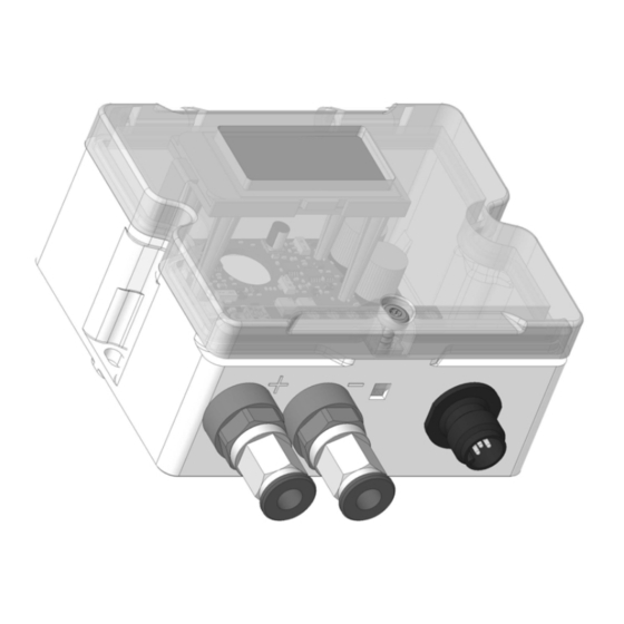
FISCHER Mess- und Regeltechnik GmbH 2 Product and functional description 2.1 Delivery scope ® • Differential pressure transmitter DE85 ECO-LINE version as stated on the type plate • Operating Manual • Closing screw for degree of protection IP65 2.2 Function diagram... -
Page 7: Equipment Versions
Product and functional description | 2 2.4 Equipment versions The DE85 is differentiated into the version with 'with measurement value dis- play' and 'without measurement value display'. Both versions are available as a 2-conductor as well as a 3-conductor version. -
Page 8: Intended Use
Production No. Fig. 5: Key 2.5 Intended use The DE85 is a differential pressure transmitter for industrial applications. It is suitable for measuring overpressure, under-pressure and differential pressure in neutral gaseous media. The device may only be used for the purpose stipulated by the manufacturer. -
Page 9: Assembly
FISCHER Mess- und Regeltechnik GmbH Assembly | 3 3 Assembly 3.1 General The device is designed for mounting onto level walls and mounting plates. To this end, the device has two installation boreholes on the side. Alternatively, an installation test can be ordered for installing the mounting rail. - Page 10 3 | Assembly FISCHER Mess- und Regeltechnik GmbH 3.2.1 Assembly instructions Release ring CK screw connection Plug nipple Pneumatic plug-in con- nection Cut the hose at right Push the hose onto the Feed the hose through to angles and place the nipple up to the stopper.
-
Page 11: Electrical Connection
FISCHER Mess- und Regeltechnik GmbH Assembly | 3 3.3 Electrical connection • By authorized and qualified specialized personnel only. • When the device is connected, national and international electrotechnical regulations must be observed. • Disconnect the system from the mains before electrically connecting the device. - Page 12 3 | Assembly FISCHER Mess- und Regeltechnik GmbH 3.3.3 Modbus (Tbd.) DE85 Auxiliary energy Δp 24 V AC/DC 5 6 7 Fig. 9: Electrical connection Modbus 12/28 BA_EN_DE85...
-
Page 13: Start-Up
FISCHER Mess- und Regeltechnik GmbH Start-up | 4 4 Start-up 4.1 General All electrical supply, operating and measuring lines, and the pressure connec- tions must have been correctly installed before commissioning. All supply lines are arranged so that there are no mechanical forces acting on the device. - Page 14 4 | Start-up FISCHER Mess- und Regeltechnik GmbH 4.3.1 Measuring range falling rising 5 6 7 asymmetric unidirectional e.g. 0 ... x symmetric bidirectional e.g. -x ... +x Pa / kPa mbar Fig. 12: Configure measuring range For example: A device with the Code D1 was ordered for the measuring range. On delivery, the device is pre-set to the basic measuring range -0.25 …...
- Page 15 FISCHER Mess- und Regeltechnik GmbH Start-up | 4 For example: The analogue output should be configured as follows for a 3-wire device with a measuring range -25 … +25 Pa: DIP switches Voltage output 2 … 10 V 4 & 5...
-
Page 16: Servicing
5 | Servicing FISCHER Mess- und Regeltechnik GmbH 5 Servicing 5.1 Maintenance The instrument is maintenance-free. We recommend the following regular in- spection to guarantee reliable operation and a long service life: • Check the function in combination with downstream components. -
Page 17: Technical Data
FISCHER Mess- und Regeltechnik GmbH Technical data | 6 6 Technical data 6.1 General Type designation DE85 Pressure type Differential pressure Measurement principle Piezo-resistive Reference conditions (acc. to IEC 61298-1) Temperature +15 to +25 °C Relative humidity 45 … 75 %... - Page 18 6 | Technical data FISCHER Mess- und Regeltechnik GmbH Characteristic curve deviation Characteristic curve dev. Measurement range Measurement range Code 1K Code 2M [mbar] [Pa] Start Start Typ. Max. Typ. Max. -0.20 … 0.80 -20 … 80 0 … 0.80 0 …...
-
Page 19: Output Sizes
FISCHER Mess- und Regeltechnik GmbH Technical data | 6 Measurement range Measurement range Characteristic curve dev. [mbar] [kPa] Code 1K Code 2M Start Start Typ. Max. Typ. Max. -100 ... 100 -10 ... 10 0 … 100 0 ... 10 -160 ... -
Page 20: Auxiliary Energy
6 | Technical data FISCHER Mess- und Regeltechnik GmbH 6.6 Auxiliary energy 3-conductor version | Modbus RTU Nominal voltage 24 V AC/DC Admissible operating voltage U 19.2 V … 28.8 V AC/DC Power consumption < 2 W 2-conductor version Nominal voltage... - Page 21 FISCHER Mess- und Regeltechnik GmbH Technical data | 6 6.9.1 Materials Materials of the parts that come into contact with the medium Plug nipple Polycarbonate PC CK screw connection Aluminium anodised Pneumatic plug connector MS nickel-plated, NBR Connection nozzle with G⅛ inner thread...
- Page 22 6 | Technical data FISCHER Mess- und Regeltechnik GmbH 6.9.2 Dimension drawings All dimensions in mm unless otherwise stated 4.25 M12 plug connector connection nozzle with inner thread G⅛ locking screw Pneumatic plug connection for pneumatic hose Ø6 or Ø8 mm...
-
Page 23: Order Codes
FISCHER Mess- und Regeltechnik GmbH Order codes | 7 7 Order codes Code no. 13 14 15 16 Type Measuring range: The basic measuring range that is stated on the type plate is printed in bold. [1.2] [mbar] [Pa] [mbar] [Pa] -0.20 ... - Page 24 7 | Order codes FISCHER Mess- und Regeltechnik GmbH [1.2] [mbar] [kPa] [mbar] [kPa] -100 ... + 100 -10 ... + 10 0 ... + 100 0 ... + 10 +100 ... - 100 +10 ... - 10 0 ... - 100 0 ...
-
Page 25: Accessories
FISCHER Mess- und Regeltechnik GmbH Order codes | 7 7.1 Accessories Assembly of the mounting rails For mounting the device on a hat rail comprising: • 2 x metal hat rail holders • 2 x M4 attachment screw Designation Order no. -
Page 26: Attachment
8 | Attachment FISCHER Mess- und Regeltechnik GmbH 8 Attachment Fig. 15: CE_DE_DE85 26/28 BA_EN_DE85... - Page 27 FISCHER Mess- und Regeltechnik GmbH Notes BA_EN_DE85 27/28...
- Page 28 Mess- und Regeltechnik GmbH Bielefelder Str. 37a D-32107 Bad Salzuflen Tel. +49 5222 974-0 Fax +49 5222 7170 www.fischermesstechnik.de info@fischermesstechnik.de Technische Änderungen vorbehalten. Subject to technical changes. Sous réserve de modifications techniques.
Need help?
Do you have a question about the DE85 and is the answer not in the manual?
Questions and answers