Table of Contents
Advertisement
Quick Links
Advertisement
Table of Contents

Related Manuals for FISCHER DE25


Summary of Contents for FISCHER DE25
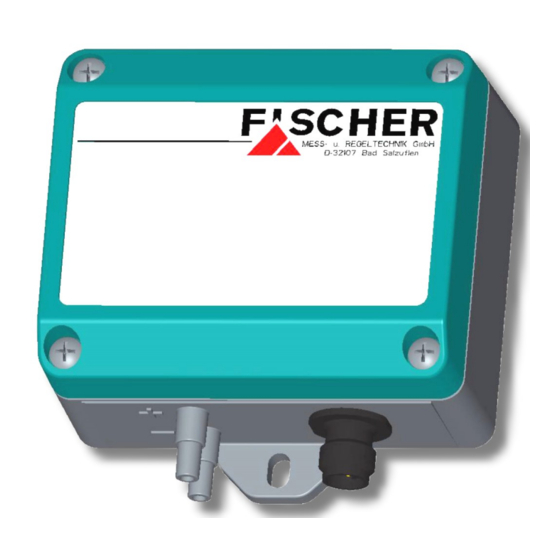
- Page 1 Operating manual DE25 Digital differential pressure transmitter for gaseous media...
- Page 2 Great care was taken when compiling the texts and illustrations; nevertheless, errors cannot be ruled out. The company FISCHER Mess- und Regeltechnik GmbH will not accept any legal responsibility or liability for this.
-
Page 3: Table Of Contents
FISCHER Mess- und Regeltechnik GmbH Table of Contents Table of Contents 1 Safety guidelines ............................ 4 1.1 General .............................. 4 1.2 Personnel Qualification.......................... 4 1.3 Risks due to Non-Observance of Safety Instructions ................ 4 1.4 Safety Instructions for the Operating Company and the Operator............ 4 1.5 Unauthorised Modification ........................ 4... -
Page 4: Safety Guidelines
1 | Safety guidelines FISCHER Mess- und Regeltechnik GmbH 1 Safety guidelines 1.1 General WARNING This operating manual contains instructions fundamental to the installation, op- eration and maintenance of the device that must be observed unconditionally. It must be read by the assembler, operator and the specialized personnel in charge of the instrument before it is installed and put into operation. -
Page 5: Inadmissible Modes Of Operation
FISCHER Mess- und Regeltechnik GmbH Safety guidelines | 1 1.6 Inadmissible Modes of Operation The operational safety of this instrument can only be guaranteed if it is used as intended. The instrument model must be suitable for the medium used in the system. -
Page 6: Product And Functional Description
FISCHER Mess- und Regeltechnik GmbH 2 Product and functional description 2.1 Delivery scope • Differential pressure transmitter DE25 ## # 042 # K00 # W • Operating Instructions 2.2 Intended use The DE25 is a differential pressure transmitter for measuring over-pressure, un- der-pressure and differential pressure in neutral, non-aggressive gaseous me- dia. -
Page 7: Function Diagram
FISCHER Mess- und Regeltechnik GmbH Product and functional description | 2 2.4 Function diagram µC +Sig Illustration 3: Function diagram 2.5 Design and mode of operation The basis of this transmitter is a piezo-resistive sensor element. The pressure that is to be measured acts directly onto a silicon diaphragm equipped with piezo-resistive resistors. -
Page 8: Assembly And Starting Operation
3 | Assembly and Starting Operation FISCHER Mess- und Regeltechnik GmbH 3 Assembly and Starting Operation 3.1 Generalities The device is designed for installation onto flat assembly plates or walls. The casing has integrated assembly straps for this purpose. Ex-works, the device is set for vertical installation. -
Page 9: Electrical Connections
FISCHER Mess- und Regeltechnik GmbH Assembly and Starting Operation | 3 3.3 Electrical connections • By authorized and qualified specialized personnel only. • When connecting the unit, the national and international electro-technical regulations must be observed. • Disconnect the system from the mains, before electrically connecting the device. - Page 10 FISCHER Mess- und Regeltechnik GmbH 3.4.1 Zero-point adjustment The differential pressure transmitters of series DE25 are set in the factory be- fore delivery so that adjustment at the assembly site is usually unnecessary. If the zero-point does need to be adjusted, this can be undertaken using the zero-point button.
-
Page 11: Maintenance
FISCHER Mess- und Regeltechnik GmbH Maintenance | 4 4 Maintenance 4.1 Maintenance The instrument is maintenance-free. We recommend the following regular in- spection to guarantee reliable operation and a long service life: • Check the function in combination with downstream components. -
Page 12: Technical Data
5 | Technical Data FISCHER Mess- und Regeltechnik GmbH 5 Technical Data 5.1 Generalities Reference conditions (acc. to IEC 61298-1) Temperature +15 … +25 °C Relative humidity 45 … 75 % Air pressure 86 … 106 kPa 860 … 1060 mbar... -
Page 13: Measurement Accuracy
FISCHER Mess- und Regeltechnik GmbH Technical Data | 5 5.4 Measurement accuracy Measuring range Characteristic curve deviation Max. 2.5 (1.0) Type 1.5 (0.5) TK span Max. Type Tk zero-point Max. %FS / 10K Type %FS / 10K Measuring range ± 2.5 ± 4 ±... -
Page 14: Construction Design
5 | Technical Data FISCHER Mess- und Regeltechnik GmbH 5.7 Construction design 5.7.1 Process connection 5.7.2 Electrical connection M12 plug connection 4-pin, male, Coding A M12 connection cable 4 x 0.34 mm sheath PUR Ø 5.2 mm (see accessories) Bending radius (fixed) 5 x Ø... - Page 15 FISCHER Mess- und Regeltechnik GmbH Technical Data | 5 5.7.5 Dimensional drawings All dimensions in mm unless otherwise stated 48,5 Mounting lug M12 Connector Process connection Cable gland M16 x 1,5 Illustration 9: Front view Illustration 10: Rear view BA_EN_DE25 15 / 20...
-
Page 16: Order Codes
6 | Order Codes FISCHER Mess- und Regeltechnik GmbH 6 Order Codes Code no. 10 11 12 Type Measuring range [1.2] Measuring range Static operating pressure 0 … 2.5 mbar 50 mbar 0 … 4 mbar 50 mbar 0 … 6 mbar 50 mbar 0 …... - Page 17 FISCHER Mess- und Regeltechnik GmbH Order Codes | 6 Output signal: (Code no.) 0 … 20 mA 4 … 20 mA 0 … 10 V Operating voltage: (Code no.) 24 V DC Electrical connection [11] (Code no.) M12 plug connection...
-
Page 18: Annex
7 | Annex FISCHER Mess- und Regeltechnik GmbH 7 Annex Illustration 11: CE_DE_DE25 18 / 20 BA_EN_DE25... - Page 19 FISCHER Mess- und Regeltechnik GmbH Annex | 7 BA_EN_DE25 19 / 20...
- Page 20 7 | Annex FISCHER Mess- und Regeltechnik GmbH 20 / 20 BA_EN_DE25...
Need help?
Do you have a question about the DE25 and is the answer not in the manual?
Questions and answers