Sign In
Upload
Manuals
Brands
FISCHER Manuals
Transmitter
PRO-LINE DE90
FISCHER PRO-LINE DE90 Manuals
Manuals and User Guides for FISCHER PRO-LINE DE90. We have
1
FISCHER PRO-LINE DE90 manual available for free PDF download: Operating Manual
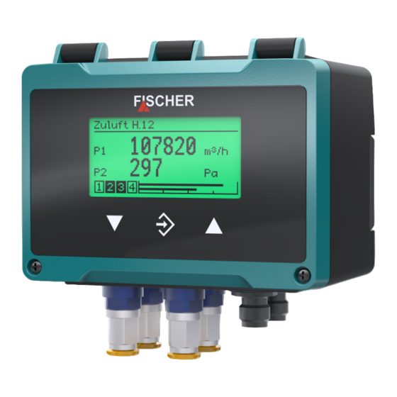
FISCHER PRO-LINE DE90 Operating Manual (116 pages)
Differential pressure transmitter
Brand:
FISCHER
| Category:
Transmitter
| Size: 6.48 MB
Table of Contents
Table of Contents
3
Safety Instructions
6
General
6
Personnel Qualification
6
Risks Due to Non-Observance of Safety Instructions
6
Safety Instructions for the Operating Company and the Operator
6
Unauthorised Modification
7
Inadmissible Modes of Operation
7
Safe Working Practices for Maintenance and Installation Work
7
Pictogram Explanation
7
Product and Functional Description
9
Delivery Scope
9
Intended Use
9
Explosion Hazard Area Classification
9
Gas Explosion Protection
9
Dust Explosion Protection
9
Function Diagram
10
Design and Mode of Operation
10
Equipment Versions
11
Type Plate
12
Assembly
13
General
13
Mounting in Explosive Areas
13
Process Connection
13
Replacement Plates
14
Cutting Ring Screw Connections
15
Electrical Connections
15
Operation in Areas at Risk of Explosion
15
Devices with Switch Outputs
16
3-Conductor Circuit
16
M12 Connector 1: Auxiliary Energy and Analogue Output
17
M12 Connector 2: Switch Outputs
17
Device with Modbus
18
Connection to an Existing Modbus RTU Network
18
Auxiliary Energy Supply
19
M12 Plug 1: Modbus in
19
M12 Plug 2: Modbus out
20
USB Port
20
Start-Up
21
Installation Control
21
Switch on the Measuring Device
21
Measured Value Display
22
Channel Version
22
Channel Version
23
Back Lighting
23
Keyboard
24
Setup
25
Set Menu Language
25
Measuring Point Designation
25
Configuration
25
Modbus RTU Interface
25
Operation
26
First Steps
26
Operating Modes
26
Menu Tree
26
Navigation in the Menu Tree
29
Directory Details
31
Input
31
Text Input
31
Value Input
32
Selection of Options
34
Main Menu
35
Login
36
Log in / Log out
37
Timeout
38
Manage Users
38
User 1
39
Administrator
40
Reset Passwords
41
Quick Access
41
Configuration
43
Channel 1
45
Mode C1
46
Measurement C1
47
Characteristic Curve C1 (Menu Expansion)
54
Number Format C1
61
Colour Change C1
62
Channel 2
67
Channel 3
68
Mode C3
69
Measurement C3
69
Characteristic C3 (Menu Expansion)
70
Number Format C3
77
Colour Change C3
77
Analog Output
78
Analog Output 1 Type
79
Analog Output 1 Assignment
79
Signal Limits
80
Switch Output
81
SP1 Assignment
81
SP1 Function
82
Switching Function
82
Display
84
Language
85
Designation
85
Measuring Data Display
85
Colour Change Assignment
86
LCD Colour
87
LCD Lighting
87
LCD Contrast
88
Modbus RTU
89
Baud Rate
90
Data Format
90
Modbus Address
91
Byte Order
91
Info
92
Service
93
Servicing
94
Maintenance
94
Transport
94
Service
94
Disposal
94
Technical Data
95
General
95
Input Variables
95
Output Sizes
96
Measuring Accuracy
97
Digital Interfaces
98
Auxiliary Energy
98
Operating Conditions
98
Display
98
Construction Design
99
Materials
99
Dimensional Drawings
99
Order Codes
101
Accessories
105
Attachments
107
EU Declaration of Conformity
107
Advertisement
Advertisement
Related Products
FISCHER DE23 Series
FISCHER DE38
fischer DE49 # 0 series
FISCHER DE49N7AR40BH00MW
FISCHER DE49N7AR25BH00MW
FISCHER DE49N7AR24BH00MW
FISCHER DE49N6A024BH00MW
FISCHER DE50
FISCHER DE46
FISCHER DE45 R/S Series
FISCHER Categories
Measuring Instruments
Transmitter
Switch
Bicycle Accessories
Automobile Accessories
More FISCHER Manuals
Login
Sign In
OR
Sign in with Facebook
Sign in with Google
Upload manual
Upload from disk
Upload from URL