FISCHER DE45 series Data Sheet And Operating Manual
De45 series digital differential pressure switch/transmitter
Hide thumbs
Also See for DE45 series:
- Operating manual (32 pages) ,
- Data sheet and operating manual (13 pages) ,
- Instruction manual (12 pages)
Table of Contents
Advertisement
Quick Links
d e v e l o p i n g
s o l u t i o n s
Data Sheet and Operating Manual
DE45
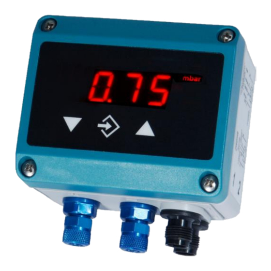
Digital differential pressure switch / transmitter
DE45##00###K0#M#R####
Gas explosion protection zone 2
Table of Content
1
Safety guidelines
2
Intended use
3
Description of the product and functional description
4
Installation and assembly
5
Commissioning
6
Maintenance
7
Transport
8
Service
9
Accessories
10 Disposal
11 Technical data
12 Dimensional drawings
13 Order Codes
14 Manufacturer's Declarations and Certificates
II 3G
Ex nA IIC T4
-10°C ≤ T
≤ 60°C
amb
1
Safety guidelines
1.1
General Information
This operating manual contains instruc-
tions fundamental to the installation, op-
eration and maintenance of the instru-
ment that must be observed uncondi-
tionally. It must be read by the assembler, operator
and the specialized personnel in charge of the de-
vice before it is installed and put into operation.
This operating manual is part of the product and
therefore must be kept close to the device in a
place that is easily accessible for the responsible
personnel.
The following sections, in particular the instructions
about assembly, commissioning and maintenance,
contain
important
safety
observance of which could lead to risks to people,
animals, the environment and objects.
1.2
Personnel Qualification
The instrument may only be installed and commis-
sioned by specialized personnel familiar with the in-
stallation, commissioning and operation of this
product.
information,
non-
Specialized personnel are persons who can assess
the work they have been assigned and recognize
potential dangers by virtue of their specialized train-
ing, their skills and experience and their knowledge
of the pertinent standards.
For explosion-proof models the specialized person-
nel must have received special training or instruc-
tion or be authorized to work with explosion-proof
instruments in explosion hazard areas.
1.3
Risks due to Non-Observance of
Safety Instructions
Non-observance of these safety instructions, the in-
tended use of the device or the limit values given in
the technical specifications can be hazardous or
cause harm to persons, the environment or the
plant itself.
Claims for damages from the manufacturer are ex-
cluded in this case.
Advertisement
Table of Contents

Subscribe to Our Youtube Channel
Related Manuals for FISCHER DE45 series


Summary of Contents for FISCHER DE45 series
- Page 1 d e v e l o p i n g s o l u t i o n s Data Sheet and Operating Manual DE45 Digital differential pressure switch / transmitter DE45##00###K0#M#R#### Gas explosion protection zone 2 Table of Content Safety guidelines Intended use Description of the product and functional description...
-
Page 2: Intended Use
This also applies to replacement parts. Any modifica- tions / alterations required shall be carried out by Fischer Mess- und Regeltechnik GmbH only. Inadmissible Modes of Operation The operational safety of this device can only be guaranteed if it is used as intended. -
Page 3: Description Of The Product And Func- Tional Description
• Description of the product and func- Check that the pressure connections do not tional description leak before commissioning. • Function diagram Maximum pressures shall be observed. Do not blow into the pressure connections! The pressure connections are marked with (+) and (-) symbols on the device. -
Page 4: Operating Keys
3 conductor circuit Display 3.5 character LED display Switching output 1 Switching output 2 230V ~ L -Sig / +Sig Delivery Delivery Trans Power Reception Analysis e.g. SPS Measuring unit Operating keys Connector 1: Power supply and output signal • The 3.5 digit LCD display represents the current differential pressure in normal mode. - Page 5 have to set the measuring value indicated below OF1 5.3.1 General points to zero. Connect the device to the power supply and ensure that it is not under any pressure (if necessary, dis- After zero-point adjustment, the pressure sensing connect any pressure lines). lines can be reconnected.
- Page 6 refer to pressure (in the relevant measuring unit) output is directly changed. You operate the device and are converted when the measuring unit is then as a transducer and can simply check the fur- changed. ther signal processing. The assigned signal values for MA and ME are invari- 5.3.7 Characteristic curve function able (type label, e.g.
- Page 7 The table comprises 3…30 pairs of values. In the tact, if the value = 2, the switch out works as a NC case of a device with a power output, the first pair contact. of values is {I01|P01} . The first value I01 defines 5.3.10 Password the output signal.
-
Page 8: Parameter Overview
Switching function Parameter overview From switching output After switching on the device, it will briefly indicate Values range 1,2 the software version number and then enters the 1 = Switching output as NO contact, normal operating mode. By using the middle û key 2 = Switching output as NC contact on the membrane keypad you can access the pa- rameter menu. -
Page 9: Maintenance
Reset Transport all parameters to standard values The device must not be exposed to mechanical (specification of the standard values shocks. It shall be transported only in packaging per PC) specifically intended for transport. Password setting Service Value range 000 to 999 Value 000 does not hold password pro- All damaged or faulty devices shall be directly sent tection. -
Page 10: Technical Data
11 Technical data + ranges (0 … ) +/- ranges mbar 100 160 250 2.5 60 100 Measuring ranges 0.4 0.6 1.0 1.6 2.5 4.0 6.0 10.0 16.0 25.0 0.25 0.4 0.6 1.0 1.6 2.5 4.0 6.0 10.0 Static operat- max. -
Page 11: Dimensional Drawings
11.1 Programming Programming is carried out via the membrane keypad and menu navigation; can be locked with a password Settings Attenuation 0.0 ... 100,0 s (jump response time 10 / 90 %) for signal output; separately also for display Switching output 1 / 2 Switch-off point, switch-on point, response time (0...100s), function (NC / NO contact) Measuring range unit mbar / Pa / "fee unit", starting value, end value and decimal point for "free unit"... -
Page 12: Order Codes
13 Order Codes Digital differential pressure switch / transmitter, with 3 ½-digit LED display Type DE45 R#### Measuring ranges 0 … 4 mbar ................ > 5 0 … 6 mbar ................ > 5 0 … 10 mbar ................ > 5 0 …... - Page 13 13.1 Accessories Order Code Designation No. of Usage Length Poles 06401993 Connection cable with M12 connector 4-pole for switching outputs 06401994 Connection cable with M12 connector 4-pole for switching outputs 06401995 Connection cable with M12 connector 5-pole for supply / signal 06401996 Connection cable with M12 connector 5-pole...
-
Page 14: Manufacturer's Declarations And Certificates
14 Manufacturer's Declarations and Certificates...
Need help?
Do you have a question about the DE45 series and is the answer not in the manual?
Questions and answers