Table of Contents

Related Manuals for FISCHER DE44


Summary of Contents for FISCHER DE44
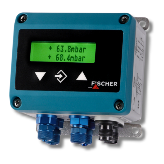
- Page 1 Operating manual DE44 ... R/S Digital 2-channel differential pressure switch/transmitter with colour-change LCD for explosive areas Dust explosion protection zone 22, dry dusts Gas explosion protection zone 2, gases and vapors...
- Page 2 Great care was taken when compiling the texts and illustrations; nevertheless, errors cannot be ruled out. The company FISCHER Mess- und Regeltechnik GmbH will not accept any legal responsibility or liability for this.
-
Page 3: Table Of Contents
FISCHER Mess- und Regeltechnik GmbH Table of Content Table of Content 1 Safety guidelines ............................ 4 1.1 General .............................. 4 1.2 Personnel Qualification.......................... 4 1.3 Risks due to Non-Observance of Safety Instructions ................ 4 1.4 Safety Instructions for the Operating Company and the Operator............ 4 1.5 Unauthorised Modification ........................ 5... -
Page 4: Safety Guidelines
1 | Safety guidelines FISCHER Mess- und Regeltechnik GmbH 1 Safety guidelines 1.1 General WARNING This operating manual contains instructions fundamental to the installation, op- eration and maintenance of the device that must be observed unconditionally. It must be read by the assembler, operator and the specialized personnel in charge of the instrument before it is installed and put into operation. -
Page 5: Unauthorised Modification
FISCHER Mess- und Regeltechnik GmbH Safety guidelines | 1 Repairs may be carried out by the manufacturer only. A professional single conformity inspection as per DIN EN 61010, section 1, must be carried out before the instrument can be re-commissioned. This inspec- tion must be performed at the manufacturer's location. -
Page 6: Product And Functional Description
2.1.1 Explosion hazard area classification Dust explosion protection Devices with the order code DE44 ## ## ## # KW # L # S#### are suitable as 'Electrical equipment for use in areas with combustible dust', Zone 22 - dry dusts. -
Page 7: Function Diagram With 4 Switching Outputs
FISCHER Mess- und Regeltechnik GmbH Product and functional description | 2 2.3 Function diagram with 4 switching outputs Δp1 Channel 1 (P1) µC þ û ÿ 1,234 Δp2 Sig 1 Channel 2 (P2) Sig 2 Illustration 2: Function diagram with 4 switching outputs 2.4 Design and mode of operation... -
Page 8: Part Designations
2 | Product and functional description FISCHER Mess- und Regeltechnik GmbH 2.5 Part designations DE44 ... R DE44 ... S Zone 2 Zone 22 Illustration 3: DE44_LCD_Overview Foil keypad LC display Casing lid Lower part of casing Circuit diagram Wall bracket... -
Page 9: Installation And Assembly
FISCHER Mess- und Regeltechnik GmbH Installation and assembly | 3 3 Installation and assembly 3.1 General The device is designed for installation onto flat assembly plates. For screw con- nection to the assembly plate, the device features four assembly bores on its back, which can be used for Ø... -
Page 10: Electrical Connections
3 | Installation and assembly FISCHER Mess- und Regeltechnik GmbH 3.3 Electrical connections WARNING Operation in areas at risk of explosion If operated in explosive areas, the electrical data of the unit and the valid local regulations and guidelines for the installation and operation of electrical systems in explosive areas must be observed (e.g. - Page 11 FISCHER Mess- und Regeltechnik GmbH Installation and assembly | 3 The device is connected as follows in a 3-wire switch: Pressure Transmitter Supply 200 mA 24 VDC +Sig 2 +Sig 1 230 VAC Input signal Output signal Illustration 6: 3L connection...
- Page 12 3 | Installation and assembly FISCHER Mess- und Regeltechnik GmbH 3.3.1 Ground connection WARNING Static electricity The case must be equipped with an earth connection on the side to reduce the surface resistance. Only devices for operation in potentially explosive areas with combustible, Zone 22 –...
-
Page 13: Commissioning
FISCHER Mess- und Regeltechnik GmbH Commissioning | 4 4 Commissioning 4.1 General All electrical supply, operating and measuring lines, and the pressure connec- tions must have been correctly installed before commissioning. All supply lines are arranged so that there are no mechanical forces acting on the device. - Page 14 4 | Commissioning FISCHER Mess- und Regeltechnik GmbH a) Model with 2 switching outputs Display: Measured value Display: Bar chart Illustration 11: LC display (2 switching outputs) The unit is shown to the right of the measured value. If the device is equipped with contacts, a closed contact is always symbolised by an inverted text "SP1"...
- Page 15 FISCHER Mess- und Regeltechnik GmbH Commissioning | 4 4.3.2 Keyboard Illustration 15: Operating keys [LC display] Page down menu Reduce value Call up menu Save value Page up menu Increase value The individual menu items and parameters can be displayed using the buttons þ...
-
Page 16: Menu Levels
4 | Commissioning FISCHER Mess- und Regeltechnik GmbH 4.4 Menu levels The menu levels are structured as follows: Outlet menu level Menu Level Reception Switch points Menu Level Input Menu Level Measuring Menu Level Output Menu Level Function Menu level... - Page 17 FISCHER Mess- und Regeltechnik GmbH Commissioning | 4 4.4.1 Menu Level Switch points (2SP) NOTICE! This menu only appears on models with two switching outputs. Parameter name Description Value range SP1 On Switch point 1 On MBA-50% … MBE+50% SP1 Off Switching point 1 off MBA-50% …...
- Page 18 4 | Commissioning FISCHER Mess- und Regeltechnik GmbH Assignment SP is used to define the input to which the contacts are assigned. The following options are available: • Channel 1 Both contacts are assigned to channel 1. • Channel 1, channel 2 A contact is assigned to every channel.
- Page 19 FISCHER Mess- und Regeltechnik GmbH Commissioning | 4 The value range ranges from MBA – 50% to MBE + 50%. MBA stands for start of measuring range and MBE for the end of the measuring range. Example: Measuring range = 0 … 100 % The value range for this measuring range is -50 % …...
- Page 20 4 | Commissioning FISCHER Mess- und Regeltechnik GmbH NOTICE Response time At maximum damping it can take over 2 minutes until after a measurement jump from 100% to 0% is also shown as zero in the display. In many cases, unsteady readings are not a problem during normal operating mode, but this is not true for the idle state, i.e.
- Page 21 FISCHER Mess- und Regeltechnik GmbH Commissioning | 4 The output signals of the transmitter primarily depend on the measured input variables (channel 1 or channel 2). However, you have the option of adjusting the output signals to a large extent to suit your requirements.
- Page 22 4 | Commissioning FISCHER Mess- und Regeltechnik GmbH of measuring range End of measuring range parameters! These para- meters primarily serve to prevent error messages in downstream systems caused by brief overstepping of measuring ranges. The parameter Min. output is usually only used for devices with an output sig- nal 4…20 mA because frequently values of below 3.8 mA are evaluated as er-...
- Page 23 FISCHER Mess- und Regeltechnik GmbH Commissioning | 4 Tables function This function allows free adjustment of the input variable to the display and out- put via a table with up to 30 support points. A value pair comprising a measured value and display value is issued for every support point.
- Page 24 4 | Commissioning FISCHER Mess- und Regeltechnik GmbH Value pair +14,6 mbar +8,6 % +0,0 ... +100,0 mbar 1 input mark (value flashes) 2 allowed range of values Illustration 18: Value pair Value pair 2 Start 100.0 Measuring range Illustration 19: Table function (example)
- Page 25 FISCHER Mess- und Regeltechnik GmbH Commissioning | 4 4.4.8 Menu Level Display The Display menu level is a variable menu whose appearance depends on the value of the colour parameter. In addition to the various colours for the back- ground lighting, there are also two auto-functions with colour switching avail- able.
- Page 26 4 | Commissioning FISCHER Mess- und Regeltechnik GmbH Auto1: Colour-change red to green If parameter Colour is set to Auto 1: red-green, the menu changes as follows: Parameter name Description Value range Assignm. switch. Assignment switching Channel 1, channel 2 Red-Gr.
- Page 27 FISCHER Mess- und Regeltechnik GmbH Commissioning | 4 Auto2: Colour-change red-yellow-green If the parameter Colour is set to Auto 2: red-yellow-green, the menu changes as follows: Parameter name Description Value range Assignm. switch. Assignment switching Channel 1, channel 2 Red-Yell.switch.
- Page 28 4 | Commissioning FISCHER Mess- und Regeltechnik GmbH The parameter Colour is set to Auto2. Only the green, yellow and red ranges Example are required here. To fade out the lower ranges red and yellow, the switch thresholds "red-yellow switching" and "yellow-green switching" are set to the start of the measuring range.
- Page 29 FISCHER Mess- und Regeltechnik GmbH Commissioning | 4 NOTICE Forgotten password The user can export and change a forgotten password using the TransPara Software. If TransPara (and EU03) cannot be used, the device needs to be re- leased by the manufacturer.
-
Page 30: Servicing
5 | Servicing FISCHER Mess- und Regeltechnik GmbH 5 Servicing 5.1 Wartung (maintenance) To ensure reliable operation and a long service life, we recommend carrying out the following test on a regular basis: • Check the reading. • Checking the switch function in connection with the downstream compon- ents. -
Page 31: Technical Data
FISCHER Mess- und Regeltechnik GmbH Technical data | 6 6 Technical data 6.1 General Please also observe the order code here. 6.2 Input variables Measuring variable 2 x differential pressure for gas-like media Measuring range Measuring range Stat. operating Bursting pressure max. -
Page 32: Measuring Accuracy
6 | Technical data FISCHER Mess- und Regeltechnik GmbH Switching outputs a) Model with 2 switching outputs 2 potential-free relay contacts 2 potential-free semiconductor switches (MOSFET) Relay MOSFET Progr. switching function Open contact (NO) One-pin activator (NO) Break contact (NC) -
Page 33: Auxiliary Energy
FISCHER Mess- und Regeltechnik GmbH Technical data | 6 Measuring range TK zero-point TK span [% FS/10K] [% FS/10K] mbar typ. max. typ. max. ±16 ±1600 ±1.6 ±25 ±2.5 ±40 ±4 ±60 ±6 ±100 Table 9: Temperature coefficient With reference to the basic measuring range (FS), Compensation range 0..60°C. -
Page 34: Application Conditions
6 | Technical data FISCHER Mess- und Regeltechnik GmbH b) Model with 4 switching outputs Connector 2 Signal name Cable colour Switching output 1 white Switching output 1 brown Switching output 2 green Switching output 2 yellow Switching output 3... - Page 35 Plug 1 M12 5-pin M12 5-pin Plug 2 Plug 2 M12 4-pin M12 8-pin DE44 with 2 switching outputs DE44 with 4 switching outputs Options for the process connection Earth connection Dust explosion protection Zone 22 Hose connection CK pneumatic plug connector for 6 or 8 mm hose for 6 or 8 mm hose Illustration 26: Ports...
- Page 36 6 | Technical data FISCHER Mess- und Regeltechnik GmbH 6.7.3 Assembly on an assembly plate The standard model is not supplied with a wall mounting plate. It is attached to flat mounting plates using attachment boreholes on the rear side.
- Page 37 FISCHER Mess- und Regeltechnik GmbH Technical data | 6 6.7.5 Assembly of the mounting rails Mounting rail adapter 61.5 The device can be mounted to the following mounting rails using the mounting rail adapter: Mounting rail acc. to EN50022 TS35 35 x 7.5 mm...
-
Page 38: Display And Operating Interface
6 | Technical data FISCHER Mess- und Regeltechnik GmbH 6.8 Display and operating interface Advertisement 4...6-digit LCD, full graphic, colour backlighting Programming Attenuation 0.0…100.0s (jump response 10/90%) Display assignment P1 and P2 are shown at the same time Switching output Switch-off point, switch-on point, delay (0...1800s),... -
Page 39: Order Codes
FISCHER Mess- und Regeltechnik GmbH Order Codes | 7 7 Order Codes Code no. 10 11 12 13 14 15 16 17 18 19 20 21 Type unused Measuring range: Channel 1 [1.2] (Code no.) 0 … 4 mbar 0 … 6 mbar 0 …... - Page 40 7 | Order Codes FISCHER Mess- und Regeltechnik GmbH [1.2] (Code no.) 0 … 1 kPa 0 … 1.6 kPa 0 … 2.5 kPa 0 … 4 kPa 0 … 6 kPa 0 … 10 kPa -1 … +1 kPa -1.6 …...
- Page 41 FISCHER Mess- und Regeltechnik GmbH Order Codes | 7 [3.4] (Code no.) 0 … 1 kPa 0 … 1.6 kPa 0 … 2.5 kPa 0 … 4 kPa 0 … 6 kPa 0 … 10 kPa -1 … +1 kPa -1.6 …...
-
Page 42: Accessories
7 | Order Codes FISCHER Mess- und Regeltechnik GmbH Device specification [17] (Code no.) Use in Zone 2 - Risk from gases and vapours II 3G Ex nA IIC T4 Use in Zone 22 - Risk from dust II 3D Ex tc IIIB T125°C IP65 -10 °C ≤... -
Page 43: Attachments
FISCHER Mess- und Regeltechnik GmbH Attachments | 8 8 Attachments 8.1 EU Declaration of Conformity Illustration 31: CE_DE_DE44_LCD_ATEX BA_EN_DE44_LCD_ATEX 43 / 44... - Page 44 8 | Attachments FISCHER Mess- und Regeltechnik GmbH 44 / 44 BA_EN_DE44_LCD_ATEX...
Need help?
Do you have a question about the DE44 and is the answer not in the manual?
Questions and answers