Table of Contents
Advertisement
Quick Links
Download this manual
See also:
Operating Manual
d e v e l o p i n g
s o l u t i o n s
Operating Manual
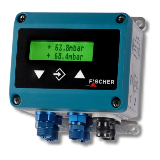
DE44
Digital two-channel
Differential pressure switch / Transmitter
Table of Content
1
Safety guidelines
2
3
4
5
6
7
8
9
1
Safety guidelines
1.1
General Information
This operating manual contains instruc-
tions fundamental to the installation,
operation and maintenance of the in-
strument that must be observed uncon-
ditionally. It must be read by the assembler, opera-
tor and the specialized personnel in charge of the
device before it is installed and put into operation.
This operating manual is part of the product and
therefore must be kept close to the device in a
place that is easily accessible for the responsible
personnel.
The following sections, in particular the instructions
about assembly, commissioning and maintenance,
contain
important
safety
observance of which could lead to risks to people,
animals, the environment and objects.
1.2
Personnel Qualification
The instrument may only be installed and commis-
sioned by specialized personnel familiar with the in-
stallation, commissioning and operation of this
product.
Specialized personnel are persons who can assess
the work they have been assigned and recognize
potential dangers by virtue of their specialized train-
ing, their skills and experience and their knowledge
of the pertinent standards.
information,
non-
1.3
Risks due to Non-Observance of
Safety Instructions
Non-observance of these safety instructions, the in-
tended use of the device or the limit values given in
the technical specifications can be hazardous or
cause harm to persons, the environment or the
plant itself.
Claims for damages from the manufacturer are ex-
cluded in this case.
1.4
Safety Instructions for the Operating
Company and the Operator
The safety instructions on correct operation of the
device shall be observed. The operating company
must make them available to the installation,
maintenance, inspection and operating personnel.
Dangers arising from electrical components, energy
discharged by the medium, escaping medium and
incorrect installation of the instrument must be elim-
inated. For more information, please refer to the
applicable national and international regulations.
In Germany these are the DIN EN, UVV and, in in-
dustry-specific cases, the DVGW-, Ex-, GL-, etc.,
the VDE guidelines and the regulations of the local
power utility companies.
Advertisement
Table of Contents

Related Manuals for FISCHER DE44


Summary of Contents for FISCHER DE44
-
Page 1: Table Of Contents
Operating Manual DE44 Digital two-channel Differential pressure switch / Transmitter Table of Content Safety guidelines Intended use Description of the product and functional description... -
Page 2: Intended Use
Function diagram also applies to replacement parts. Any modifica- tions / alterations required shall be carried out by Fischer Mess- und Regeltechnik GmbH only. Inadmissible Modes of Operation The operational safety of this device can only be guaranteed if it is used as intended. The device model must be suitable for the medium used in the system. - Page 3 If the device is intended for outdoor use, we rec- Connector 1: Power supply and output signal ommend permanently protecting the membrane keypad against UV radiation and using a suitable bridged internally enclosure or at least the erection of a sufficiently dimensioned canopy as a protection measure against constant rain or snow.
-
Page 4: Commissioning
Configuration Commissioning For commissioning there is a multitude of setting All electrical supply, operating and measuring lines, options for optimum adaptation of the device to the and the pressure connections must have been cor- measuring point and task at hand. This section co- rectly installed before commissioning. - Page 5 Display settings ro. Within this range, the measuring value is set to zero. Due to the fact that the DE44 has two independent pressure measuring systems but only one display, Example: you can use the dSP parameter to select whether is entered for NP.
- Page 6 The difference between values MA and ME must at ing variable (e.g. volume in m³ or volume flow cm³/s etc.) least be 25 % of the basic measuring range. The software does not allow any larger spreads. If the The parameter F allows you to select between the range information is stated wrongly, you cannot following variants: leave the menu.
- Page 7 The table is correct if the following applies for all If the password is forgotten, it can only signal values: The value is larger than the previous be reset by the manufacturer or over- value. Either larger (rising characteristic curve) or written via the PC adapter.
- Page 8 Switch-on point Free unit From switching output End of measuring range (display) Switching delay Offset correction measuring input 1 Value range -⅓ FS...0... +⅓ FS from switch output • Value range 0.0 to 100.0s. This value Characteristic curve function applies equally for switching on and off.
-
Page 9: Maintenance
Maintenance Service The device is maintenance-free. All damaged or faulty devices shall be directly sent to our repair department. Please coordinate the re- We recommend regular inspections to guarantee turn of any device with our sales department. reliable operation and a long life cycle, such as: Process media residues... -
Page 10: Technical Data
11 Technical data Positive ranges (0 … ) +/- ranges mbar 40 60 100 ±2.5 ±4 ±6 ±10 ±16 ±25 ±40 ±60 ±100 Basic measuring range 400 600 1000 1600 ±250 ±1 ±1.6 ±2.5 ±4 ±6 Max. stat. operating pres- mbar sure Bursting pressure... -
Page 11: Dimensional Drawings
11.1 Programming Programming is carried out via the membrane keypad and menu navigation; can be locked with a password Settings Attenuation 0.0 ... 100.0 s (jump response time 10 / 90 %) for signal output; separately also for display Selection of the displayed measuring 0.0 = only differential pressure 1 (dP1) value 0.1 = only differential pressure 1 (dP1) -
Page 12: Order Codes
13 Order Codes Digital 2-channel differential pressure switch/transmitter with 3 ½-digit LED display DE44 Channel 1 - measuring range 0 … 4 mbar ..........> 0 … 6 mbar ..........> 0 … 10 mbar ..........> 0 … 16 mbar ..........>... - Page 13 Digital 2-channel differential pressure switch/transmitter with 3 ½-digit LED display DE44 Channel 2 - measuring range 0 … 4 mbar ..............> 0 … 6 mbar ..............> 0 … 10 mbar ..............> 0 … 16 mbar ..............>...
- Page 14 Digital 2-channel differential pressure switch/transmitter with 3 ½-digit LED display DE44 Pressure connection Aluminium screw connection for 6 / 4 mm hose ..........> 4 Aluminium screw connection for 8 / 6 mm hose ..........> 4 Electrical output signal (only channel 1) without analogue electrical output signal ..............
-
Page 15: Declaration Of Conformity
14 Declaration of Conformity... - Page 16 Technische Änderungen vorbehalten • Subject to change without notice • Changements techniques sous réserve Fischer Mess- und Regeltechnik GmbH • Bielefelder Str. 37a • D-32107 Bad Salzuflen • Tel. +49 5222 9740 • Fax +49 5222 7170 • eMail: info@fischermesstechnik.de • www.fischermesstechnik.de...
Need help?
Do you have a question about the DE44 and is the answer not in the manual?
Questions and answers