Table of Contents
Advertisement
d e v e l o p i n g
s o l u t i o n s
Operating Manual
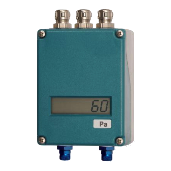
DE50
Differential pressure transmitter
Table of Contents
1
Safety guidelines
2
3
4
5
6
7
8
9
1
Safety guidelines
1.1
General Information
This operating manual contains instruc-
tions fundamental to the installation,
operation and maintenance of the in-
strument that must be observed uncon-
ditionally. It must be read by the assembler, opera-
tor and the specialized personnel in charge of the
instrument before it is installed and put into opera-
tion.
This operating manual is part of the product and
must be kept close by where it is easily accessible
to the responsible specialized personnel.
The subsequent sections, in particular the instruc-
tions on assembly, commissioning and mainte-
nance, contain important safety instructions, non-
observance of which can endanger persons, ani-
mals, the environment and physical objects.
1.2
Personnel Qualification
The instrument may only be installed and commis-
sioned by specialized personnel familiar with the in-
stallation, commissioning and operation of this
product.
Specialized personnel are persons who can assess
the work they have been assigned and recognize
potential dangers by virtue of their specialized train-
ing, their skills and experience and their knowledge
of the pertinent standards.
1.3
Risks due to Non-Observance of
Safety Instructions
Non-observance of these safety instructions, the in-
tended use of the instrument or the limit values giv-
en in the technical specifications can be hazardous
or cause harm to persons, the environment or the
plant itself.
The manufacturer will not be liable for damage
claims if this should happen.
1.4
Safety Instructions for the Operating
Company and the Operator
The safety instructions on correct operation of the
instrument shall be observed. The operating com-
pany must make them available to the installation,
maintenance, inspection and operating personnel.
Dangers arising from electrical components, energy
discharged by the medium, escaping medium and
incorrect installation of the instrument must be elim-
inated. For more information, please see the appli-
cable national and international regulations.
In Germany these are the DIN EN, UVV regula-
tions, specific industrial guidelines such as DVGW,
Ex, GL, etc., the VDE- regulations and the regula-
tions of the local energy supply companies.
P a g e
| 1-12
Advertisement
Table of Contents

Related Manuals for FISCHER DE50


Summary of Contents for FISCHER DE50
-
Page 1: Table Of Contents
Operating Manual DE50 Differential pressure transmitter Table of Contents Safety guidelines Application purpose Description of the product and functional description Installation and assembly... -
Page 2: Application Purpose
This Functional Schematic also applies to replacement parts. Any modifica- tions / alterations required shall be carried out by Electronics Output (linear) Fischer Mess- und Regeltechnik GmbH only. Output (rooted) Inadmissible Modes of Operation Switch contact Inductive displacement transducer... -
Page 3: Commissioning
the zero-point signal can be corrected via the in- Electronic connection stalled zero-point adjuster. • By authorized and qualified specialized person- If the pressure sensing lines are already nel only. pressurised at the time of commission- • The electrical connection of the instrument shall ing, zero-point control and adjustment be performed according to relevant VDE and cannot be performed. - Page 4 5.2.1 Display range Zero point Steepness 5.2.2 Measuring range and switch points Coding switch Switch points Measuring range Settable damping reactors MZ41 Actual value Zero point Switch point K1 Steepness Switch point K2 In the operational status, the reactor pins need to be set so that the measurement display follows the pressure changes with a delay.
-
Page 5: Maintenance
• It is sensible to check the zero point and meas- 5.4.2 Switch point K2 uring range end value again (adjust if neces- The switch point K2 is set in the same way as sary). switch point K1 (see above). However different in •... -
Page 6: Technical Specification
11 Technical Specification General points 0 … 4 mbar to 0 … 600 mbar Measuring ranges (see order code) Max. stat. operating pressure 3 bar (see order code) Max. pressure load Over-pressure-proof up to permissible operating pressure Measuring accuracy ± 1 % of the measuring range Temperature drift 0.5 % /10 K Admissible ambient temperature... -
Page 7: Dimensional Drawings
12 Dimensional drawings (All dimensions in mm unless otherwise stated) M16x1.5 screw connection Assembly boreholes Ø 4.5 P a g e | 7-12... -
Page 8: Order Codes
13 Order Codes Differential pressure transmitter DE50 Measuring range Stat. operating pressure 0 ... 1.6 mbar 8 mbar (Cl.:2.5) ..> 9 8 mbar (Cl.:2.5) ..> 9 0 ... 2.5 mbar 0 ... 4 mbar 20 mbar ....> 5 0 ... -
Page 9: Declaration Of Conformity
14 Declaration of conformity P a g e | 9-12... - Page 10 10-12 | Page...
- Page 11 P a g e | 11-12...
- Page 12 Technische Änderungen vorbehalten • Subject to change without notice • Changements techniques sous réserve Fischer Mess- und Regeltechnik GmbH • Bielefelder Str. 37a • D-32107 Bad Salzuflen • Tel. +49 5222 9740 • Fax +49 5222 7170 • eMail: info@fischermesstechnik.de • www.fischermesstechnik.de...
Need help?
Do you have a question about the DE50 and is the answer not in the manual?
Questions and answers