Table of Contents
Advertisement
Quick Links
Advertisement
Table of Contents

Related Manuals for Logosol Smart Set


Summary of Contents for Logosol Smart Set
- Page 1 USER MANUAL SKU. 0458-395-5352 REV:1 UP DOWN SMART SET FOR PETROL ENGINE...
- Page 2 We are very pleased that you have demonstrated your confidence in us by purchasing this machine and we will do our utmost to meet your expectations. LOGOSOL has been manufacturing sawmills since 1989, and in that time we have supplied approximately 50,000 machines to satisfied customers the world over.
-
Page 3: Table Of Contents
TABLE OF CONTENTS Safety instructions Maintenance Technical specification Components: on delivery Assembly Adjustment of throttle Starting and stopping Functions Troubleshooting guide... -
Page 4: Safety Instructions
SAFETY INSTRUCTIONS KEY TO SYMBOLS WARNING! This symbol means that Always use approved hearing protection you should pay particular attention and is when working with the machine. Even always followed by information about the brief exposure to high frequency noise relevant risk. - Page 5 Here is a description of the safety features of the Always have a fully-stocked first aid kit Smart Set controls together with their functions. available at the workplace. Emergency stop on the control unit On the control unit there is an emergency stop that shuts off both the control panel and the engine.
-
Page 6: Maintenance
Note that the battery capacity is only for powering the Smart Set, the capacity is not sufficient for additional power consumption. Use Smart Set when the engine is running otherwise the battery may become discharged. -
Page 7: Technical Specification
TECHNICAL SPECIFICATION Recommended maximum length of log bed: A maximum of 2 extensions is recommended when using Smart Set. Weight: 90 kg Electrical system: 12V BOLTS/NUTS Definition of the fasteners on following pages. Shoulder bolt Allen screw Cross screw Allen screw (partially threaded) -
Page 8: Components: On Delivery
COMPONENTS PARTS: ON DELIVERY BOX-MF 8 x – M8x60 03-02140 8 x – M8 8 x – M8 03-02332 8 x – M6x12 SKP-BOXMF 6 x – M8 5 x – M8x12 BOX-M 03-02282 03-02869 01-00632 03-02150 04-00240 SKP-BOXM 01-00631... - Page 9 BOX-EC 01-00396 BOX-CB 01-00372 BOX-EP 02-00466 05-00035 4 x – M4x8 4 x – M4 2 x – M6x16 2 x – M6 SKP-BOXEP...
- Page 10 2 x – 04-00063 2 x – M10 BOX-DV 2 x – M10x35 4 x – M10 SKP-BOXDV 2 x – M6x30 2 x – M6 01-00452 2 x – 04-00443 03-02963 03-02525 4 x – M8x65 03-03044 4 x – M8 03-02668 4 x –...
- Page 11 BOX-TP 03-03121 03-03043...
- Page 12 The below items will also be supplied depending on your model of band sawmill B751 PRO 01-00688 B751 PRO 03-02965 B1001 01-00784 B1001 03-02489 01-00617 Operation arm Needed for assembly. Note. Not included in these packs 02-00465 02-00487 2 x – M8x20 02-00449 1x –...
-
Page 13: Assembly
Let’s get started! We recommend laying out all fasteners on a tray or similar to make it easier to find screws. Symbol: Assembly... - Page 14 06BZ21 18SBB13 BOX-MF & BOX-M Note. Note the orientation of the sprocket. 03-02282 4 x – M6x12 03-02869 4 x – M6x12 06B1Z28 Note. Note the orientation of the sprocket. 8 x – M8x60 8 x – M8 8 x – M8...
- Page 15 BOX-DV 2 x – M10x35 4 x – M10 01-00536 When installing the extensions of the log bed, 01-00536 extension chains should be used, 1 extension chain for each rail extension added 2 x – M6...
- Page 16 BOX-DV Extension chain 01-00421 is required when mounting a trailerkit to the rail. Trailer kit 01-00421 Tighten the supply chain manually as much as possible before it is mounted on the chain lock. 2 x – M6x30 4 x – M6 04-00443 2 x –...
- Page 17 BOX-EC 5 x – M8x12 BOX-DV B751 PRO 01-00688 B1001 01-00784 1 x – MVBF M10x55 Note. Removal of this part applies solely to B1001.
- Page 18 1 x – M5x16 1 x – M5 04-00624...
- Page 19 4 x – M8x65 4 x – M8 4 x – 03-02502 B751 PRO 03-02965 B1001 03-02489 Note the length of the hose specified between the hose clamp and the upper attachment. The length of the hose is important so that it does not become knotted together or become too long in its end positions.
- Page 20 01-00617 2 x – M8x20 78,5mm 1 x – M12x100 +M12 1 x – M12 4 x – M6x16 4 x – M6 BOX-CB 4 x – M8x16 4 x – M8 2 x – M4x8 2 x – M4...
- Page 21 BOX-EP 2 x – M6x16 2 x – M6 2 x – M4x8 2 x – M4 BOX-DV 3 x – M8x12 The signal cable can be mounted on the left side of the sawhead as an option. The cable is then secured with Velcro according to step 21.
- Page 22 BOX-DV 01-00690 03-03129 03-03130...
- Page 23 The below items can be found in the petrol engine saw pack. 03-02194 04-00223...
- Page 24 CONNECTING MOTOR CONTROLS Black Main fuse BLUE Stop signal motor CONNECTING THE BATTERY CONNECTION, BLUE...
- Page 25 BOX-TP 6 x – M8 5 x –M6X10 5 x – M6...
- Page 26 05-00004 is required, 1 cable extension per 2 extensions. INSTALLING CONTROL CABLE 2 x – M6x20 2 x – M6 Feed to Smart Set Midi/ATO 10A Control Box 2 x – M6 FUSES The machine has a number of fuses, some at the top of the battery and four fuses on the upper part of the component panel.
-
Page 27: Adjustment Of Throttle
THROTTLE ADJUSTMENT - BRIGGS 23HK WARNING! Risk of serious injury. WARNING! Risk of burn injuries. The engine and its muffler get very hot during operation and remain hot for a while after shutdown. Before adjusting the throttle cable’s tension on the engine: turn the ignition knob to the Allow the engine and the muffler to cool OFF position and close the fuel valve. -
Page 28: Starting And Stopping
STARTING AND STOPPING STARTING 1. Open the fuel valve by moving the slide control to the right to the "ON" position. 2. To start a cold engine, set the choke to closed position (lever to the left). To start a warm engine, leave the choke in open position (lever to the right). -
Page 29: Functions
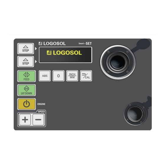
FUNCTIONS Control unit The Logosol Smart Set control unit includes a display, a number of programs and settings buttons, as well as an enabling switch button and a control lever. To use the different functions, select the desired function on the control panel. To subsequently execute the command, the enabling switch button must be pressed in at the same time as the operation is performed with the operating lever. - Page 30 FUNCTIONS PROGRAM KEYS Up/down Up / Down activates the ability to move the vertically. UP DOWN The feed button is used to run the sawhead back and Saw mode / Start forth over the rails. Activates the engine to enable sawing. The engine revs REVVING UP up and runs at working speeds until the operating lever THE ENGINE...
- Page 31 Cal key to put the machine in the calibration mode. Restart Smart Set and press the Cal button after the start process. You then move the sawblade with the control lever until it comes to the calibration value 100 mm from the log bed.
- Page 32 FUNCTIONS CANCEL COMMAND The calibration key has two functions; it also works as a command for cancelling a selected operation. Pressing this key returns the machine to standby mode. ENABLING SWITCH BUTTON The machine’s enabling switch button is the big button located below the control lever to the right of the control panel.
- Page 33 SETTING STEP MODE Set the Step mode by pressing down one of the step keys. This has to be done with the Smart Set in its standby mode. Keep the sawing dimension key pressed down and then enter the desired value using the control lever.
- Page 34 SAWING A LOG The illustration below shows an example of a workflow, with the steps that are performed by the Smart Set during sawing. START POSITION To make a cut, begin by setting the Activate the feed and start the engine Feed the blade through the log using sawblade to the desired height.
- Page 35 FUNCTIONS PERFORM FUNCTIONS To run the different functions in Smart Set, you follow the steps as shown in the illustration below. Select the desired function on the keypad. Keep the enabling switch button pressed down. Carry out the selected operation using the control lever.
- Page 36 FUNCTIONS DIMENSIONING The Smart Set interface can display several different measurements and units to make it easier for the user in different situations. The interface is set in the starting position to show an absolute measurement between the saw blade and the log bed in mm.
-
Page 37: Troubleshooting Guide
The sawhead passes below Restart the Smart Set and recalibrate the sawhead. the bottom position or above 100mm between saw blade and log bed. the maximum position. - Page 40 Fiskaregatan 2, SE-871 33 Härnösand, SWEDEN +46 611 182 85 | info@logosol.com | www.logosol.com...
Need help?
Do you have a question about the Smart Set and is the answer not in the manual?
Questions and answers