Table of Contents
Advertisement
Quick Links
Advertisement
Table of Contents

Related Manuals for Logosol M7


Summary of Contents for Logosol M7
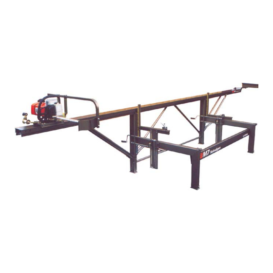
- Page 1 Sawmill Manual Read the safety instructions. Customer order no: M7 serial no:...
- Page 2 Metric Parts Sizing Chart M6x30 Bolt Sawmill Bolt Sizes 30 mm Metric scale in mm Collar nut Collar bolt Allen head bolt...
- Page 3 Please print legibility Chainsaw serial number: I have read and understood the chainsaw operating manual including sa- fety rules and instructions. INITIAL: I have read and understood the Logosol sawmill operating manual inclu- ding safety rules and instructions. INITIAL: SIGNATURE: DATE:...
- Page 4 Folde World Service Tape...
-
Page 5: Table Of Contents
Contents You are now the owner of a Safety Instructions Design and construction of Logosol M7 Portable Sawmill, Description the M7 Portable sawmill, plus the result of our collective Technical specifications manual text and pictures: experience and dedicated Assembly Mattias Byström. -
Page 6: Safety Instructions
Wear a safety helmet other drugs or medicines that manual carefully before using with hearing protection might cause drowsiness or in- the M7. Failure to observe these and a face shield. attention. safety instructions may result in fatal injury. Remember that hearing can... - Page 7 The overall max. load capacity Do not make any alterations in possible in order to reduce the of the M7 is 500 kg (1100 lbs). the construction of the sawmill risk of it coming loose due to The 2.5 m extension increases as this can increase the accident vibrations during sawing.
-
Page 8: Description
The only parts to adjust are the were needed in earlier models. M6 fit on the M7 as well. guide rail and the height of the Most of the aluminium parts are log bed, in all three bolts. -
Page 9: M7 Components
M7 Components What follows is a brief description of the M7 components to assist in identifying them during assembly. A more complete listing is found at the end of the manual. Guide rail Joint coupler Long leg Horizontal beam Short leg... -
Page 10: Assembly: Frame
Assembly: Frame Part number Description 4507-001-1200 Horizontal beam 4507-001-1035 Short leg 4507-001-1030 Long leg 4507-001-1045 Knee fitting 4507-001-1060 Angle fitting 4507-001-1040 Foot 4507-001-2071 Screw bag # 71 The right and left leg units of Tighten all four bolts Finally tighten the bolts between the frame are assembled in the loosely to allow the beams the horizontal beam and the... -
Page 11: Assembly: Guide Rail
Assembly: Guide Rail Part number Description 4507-001-1000 Guide rail 2.75 m (9ft) 4510-720-6700 Joint coupler 300 mm (12”) 4510-723-0800 Joint plate 4507-001-2072 Screw bag # 72 Hole placement in the ends Fit the other guide rail Insert the joint coupler in one of the guide rail differs and section over the joint coupler and end of the first guide rail section... - Page 12 20 mm into the the long leg (A) pulling the strut M7 unit (C). (6 x M6x20 collar adjusting strut. Do not tighten right up against the leg. (1 x bolts, 6 x M6 square nuts) this bolt.
-
Page 13: Assembly: Guide Rail Strut
Assembly: Guide Rail Strut part number Description 4507-001-1015 Guide rail strut 4507-001-2073 Screw bag # 73 (12) (13) Place the guide rail on the Fit the struts to the inside long legs, pressing the guide (D) of the guide rail flanges rail down while the bolts are with the oval hole up. -
Page 14: Assembly: Log Side-Rest
Assembly: Log Side-Rest (14) Fit the log side-rest. Make sure that the measuring scales are both facing in towards the center of the mill so that the operator can read both scales from the center position. (2 x M6x20 bolts, 2 x M6 collar nuts) (15) Place the plastic slide rail... -
Page 15: Assembly: Saddle Plate
Assembly: Saddle Plate (20) Thread the lifting line through the hole in the lower part of the saddle plate and make the knot shown (A). Leave a 1 cm (3/8”) end after the knot. (21) Press the steel sleeves into the holes in the plastic glides. -
Page 16: Assembly: Edge Support
Assembly: Crank and Lifting Line (24) Thread the lifting line under the outside pulley of the lifting beam, straight up and around the pulley on the horizontal beam (A) and then down again to the inner pulley on the lifting beam. - Page 17 Assembly: Saw Carriage Part number Description 9999-000-1032 Spool with crank, compl. 4510-720-2800 Spool holder 4507-720-7402 Sliding block, aluminium 4510-720-2900 Pylon bracket 4510-723-2002 Feed line 4510-723-2904 Plastic slide, carriage 4507-001-2076 Screw bag # 76 (26) (28) (29) Insert bolts through the Insert the square nuts Thread the line spool over holes along the sides of both...
-
Page 18: Assembly: Chain Guard
The guide bar nuts will later be used to fasten the chainsaw to the carriage. Only CE-approved chain- saws with two guide bar nuts may be used with the M7 sawmill. Part number Description 4510-723-3402 Logosol nut 066... - Page 19 Screw the chainsaw’s chainsaw models the rear hole app. 4 cm (1 1/2”) from the tip of guide bar nuts onto the Logosol the guide bar. (2 x M6x40 bolts, extender nuts under the plate 2 x M6 collar nuts) and tighten.
-
Page 20: Assembly: Spiked Log Grip
The guard extension is exits the log! The guard an accessory, which can extension must be fitted when be ordered from Logosol. See a guide bar longer than 45 the parts list at the end of the cm (18”) is being used. The manual. -
Page 21: Siting
(6.5 ft) long. The boards must While the goal is to have the Example of log feed. extend at least 0.5 m (1.6 ft) M7 sawmill fully level, any tilt, beyond the long legs. however slight, must not be Secure the logs with away from the operator as this wedges. -
Page 22: Adjustments - Guide Rail
Adjustments – Guide Rail To check the straightness of the Adjust the guide rail guide rail, remove the carriage straightness using the M10 and log grip. Sight along the bolt and the inner nut on the guide rail from one of its upper adjusting strut. -
Page 23: Adjustments - Log Bed
Adjustments – Log Bed plastic slide rail on the log Use the bolt and inside Check that when the log bed (D) and adjust it so that nut on the rachet bar to move bed is cranked down, it moves it is straight in relation to the the log bed up until the setting easily through the saddle plate... -
Page 24: Adjustments - Guide Bar
This can be compensated for by placing one or more adjustment pieces between the aluminium sliding rails and the chainsaw or electric saw plate. Adjustment pieces can be ordered from Logosol, part. no. 4507-001-1305. - Page 25 Step-by-Step Sawing Instructions Roll the log onto the log Cut the slab and perhaps bed. one more board. Fasten the log in place Rotate the cant 90° and using the edge support. Place the fix with the edge support arms. edge support arms backwards Set the height so that a suitable and lock the block in place using...
- Page 26 2”. Make sure you do not saw into the edge support spring arms. Many of us here at Logosol Quarter sawing provides you can share our years of sawing with the finest material. You experience with you. As a new...
-
Page 27: Material Drying
Begin by halving and quartering One example when you ought to be the same thickness (1x1” the log. When sawing the boards use undried wood is building log or 1x2”) and dry. You can get out of the quarters, you turn structures. -
Page 28: Trouble-Shooting
M7 is that the chain is dull beds are fully parallel. Use Stihl are used. (see page 30). the setting block included The set-up of the M7 with the machine. - Page 29 As long special accessories designed are faulty or that some are as the guide bar continues for the M7 to support the missing, such as after sawing to lie just above the newly ends of long logs (articulated...
-
Page 30: Precision Of The Logosol
We are convinced that the planed. When designing the sawmill, M7 sawmill can provide as we have taken this into If you have gone through the good or better results as consideration, so possible... -
Page 31: Cutting Equipment
Cutting equipment maintenance. If you have an worn lopsidedly. Even if you The Logosol PMX chain pro- electric saw, you will need change the chain, a worn vides for rapid ripping with a file block (part. no. 9999- down guide bar can steer a narrow kerf. - Page 32 If you don’t file in time, you However, after between 50 will have to remove a lot of and 100 cuts with the M7 the cutter to get it sharp. sawmill, the edge in the The working life of the chain chromium layer will be worn will be short.
-
Page 33: Fine-Tuning The M7
You will attain the Logosol Sawmill has no we have designed the M7 best precision if a bar shorter importance whatsoever as to have as few adjusting than 50 cm (20”) is used. -
Page 34: Fine-Tuning The
You Place the boards at different on both the log beds. Push can buy schims from Logosol, positions on the guide rail. If the log bed outwards when but you can just as well cut the boards (or spirit levels) measuring. - Page 35 C o n g r a t u l a t i o n s ! N o w when measuring. If you do not you have an exceptionally get the same measurements accurately adjusted M7 at both the inner and the outer Sawmill. end of the log bed, you have If you are careful with the to adjust this.
- Page 36 Fine-tuning the joint couplers. When two guide rails are coupled together, you often get a small difference in level on the sliding surface, which can make it difficult for the saw unit to run or make it bump as it passes the joint. This can easily be adjusted at the joint coupler.
-
Page 37: Accessories
Logosol offers a great range of extensions, special tools and other accessories for the M7 sawmill. Simple extensions can be bought in 0.5 or 1 m lengths (1.6 – 3.2 ft). It is possible to extend the M7 both at the ends and in the middle. -
Page 38: Parts List
Spool holder * 30. 4507-001-1150 Rachet bar 57. 4510-720-2900 Pylon carriage bracket * 31. 4507-001-1115 Scale selector 58. 4510-723-3402 Logosol nut 066 * 32. 4507-001-1120 Turn spring 59. 4510-723-3404 Logosol nut 088 * 33. 4507-001-1125 Rachet Cam 60. 4507-001-1500 Adjusting plate 70 x 10 x 0.5 mm * 34. -
Page 39: Build A Bench
Design: Mattias Byström Design: Mattias Byström Build a bench! Build a bench! or two while you’re at it. or two while you’re at it. To produce the two diagonally sawn boards, It only takes an hour or two from log to make a 7”... -
Page 41: Eu Declaration
Machine Directive 89/392/EEC, as amended, and in accord with the following harmonised standard: EN 292. The M7 portable sawmill may only be used in combination with Logosol’s sawing units E 5000, E 3000 and BS 320 or with a chain-saw that satisfies the specifications in Machine Directive 89/392/EEC, as amended, and is fitted with two guide bar nuts for fastening to the carriage. - Page 44 LOGOSOL USA P.O. Box 660, Madison MS 391 30 Tel. +1-601-656 18 89 Fax +1-601-856 95 35 www.logosol.com info@logosol.com LOGOSOL UK The Sawmill, Abbey St Bathans, Duns, Berwickshire TD11 3TX Tel. +44-1361 840 251 Fax +44-1361 840 389 www.logosol.co.uk enquiries@logosol.co.uk...
Need help?
Do you have a question about the M7 and is the answer not in the manual?
Questions and answers