Table of Contents
Advertisement
USER MANUAL
USER MANUAL IN ORIGINAL FORMAT.
ARTICLE NO: 0458-395-0802
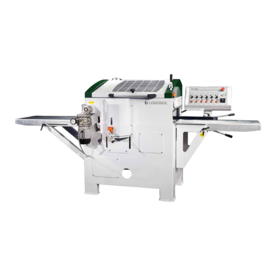
LOGOSOL PH360
Read through the user manual carefully and make sure you understand its contents
before you use the planer/moulder.
This user manual contains important safety instructions
WARNING! Incorrect use can result in serious personal injury or even death to the
operator or others.
Advertisement
Table of Contents

Related Manuals for Logosol PH360


Summary of Contents for Logosol PH360
-
Page 1: User Manual
USER MANUAL USER MANUAL IN ORIGINAL FORMAT. ARTICLE NO: 0458-395-0802 LOGOSOL PH360 Read through the user manual carefully and make sure you understand its contents before you use the planer/moulder. This user manual contains important safety instructions WARNING! Incorrect use can result in serious personal injury or even death to the... - Page 2 Bengt-Olov Byström Founder and Chairman of the Board, Logosol AB LOGOSOL is engaged in continuous development of its products. We must therefore reserve the right to change the design and form of our products. Text: Bo Mårtensson Document: Logosol PH360 Manual Image: Bo Mårtensson, Lars Wahlström...
-
Page 3: Table Of Contents
Top cutter Molding knife in bottom and top cutter Side cutters Instruction variable Maintenance Setting the upper chassis' plan Molding tips Starter package PH360: molding knives & examples of combinations Electrical schematic Technical data List of components Overview EC Declaration... -
Page 4: Safety Instructions
Contact KEY TO SYMBOLS Logosol for information regarding training in machine planing. For your own safety, read the entire instruc- tion manual carefully and do not start the •... -
Page 5: Environmental Requirements
6 m (20 ft) Hard materials such as chipboard, teak, MDF, etc. The operator's work area Max 8 m (26 ft) require hard carbide tools, see the Logosol-Toolbox catalogue. (10 ft) The barrier behind The planer/moulder is designed for indoor use, with the infeed side temporary outdoor use. -
Page 6: Tools Required
They could have been left in the planer/moulder! MACHINE DESCRIPTION The PH360 is a planer/moulder that can work four The cutters and feed rollers are covered by a folda- sides of a workpiece in one action. The planer/moul- ble protective cover plate with window. -
Page 7: Preparations
LOGOSOL PH360 PREPARATIONS Certain parts are not assembled on delivery for Figure 1. transport and packaging reasons. 1. Assemble the control panel in place with the arm where the cabling goes, (232), (251). 2. Assemble all safety doors. 3. Assemble the infeed table (212). [Figure 1] •... -
Page 8: Setup
8-10 mm (3/10"- 4/10"). CHIP MANAGEMENT The PH360 must be connected to a chip fan with a Chips that are left in the planer/moulder must capacity of at least 3,000 m /h (10,000 cubic feet/ be vacuumed up after every work session. -
Page 9: In And Outfeed Table
LOGOSOL PH360 IN AND OUTFEED TABLE Note that the outfeed table can easily be folded up outfeed marks (snipe). This particularly applies when so you can move around the planer. thin or soft workpieces are being processed. The outer edges must then always lie slightly higher than The tables must mainly be completely in line with the planer table. -
Page 10: Control Panel
CONTROL PANEL CONTROL PANEL The button's function is from the right: The top red button (a11) is the emergency stop and 1. Starting the planer cutter (lower horizontal cutter) switches off the power to all functions. When the 2. Starting the side cutter, right emergency stop is used, it must be pulled out again 3. -
Page 11: Bottom Cutter
38 degrees. You can order a grinder from when you are tightening screws (see warning Logosol for sharpening molding and planing knives instructions). Beware of the planer knives. It is (Tormek Grinder, item no. 7010-000-1000, Jig for extremely easy to cut yourself on these, even planing knives, item no. - Page 12 use a magnetic knife setter (magnetic adjuster, lower cutter, item no. 7500-001-0051): Loosen the chip breaker's lock screws and tighten the knife's adjustable screws several turns. Rotate the cutter so that the planing knife is in its up- permost position. Place the magnetic adjuster straight and in a V-shape on the planer table be- hind the cutter so that the knife edge is directly under the magnetic adjuster's magnets.
-
Page 13: Top Cutter
LOGOSOL PH360 TOP CUTTER Before you open the safety doors on the planer, ensure that the power is switched off and that the cutters are not rotating. Use protective gloves, particularly when you need to loosen screws that are tightly fastened, or when you are tightening screws (see safety instructions). - Page 14 When the top cutter's bearing housing is adjusted, or when the planing knife's cut is changed, the counter's pre-set must be height calibrated. ADJUSTMENT OF THE TRAPEZOIDAL THREADED BAR'S CHAIN TRANSMISSION The chain, which raises and lowers the table, must not be slack, but needs to be tensioned enough that teeth bite correctly.
-
Page 15: Molding Knife In Bottom And Top
LOGOSOL PH360 MOLDING KNIFE IN BOTTOM AND TOP CUTTERS Before you open the safety doors on the • To insert knives into the top or bottom cutter planer, ensure that the power is switched heads, a gib/moulding knife clamp must be used to hold the knife in the head. -
Page 16: Side Cutters
SIDE CUTTERS Before you open the safety doors on the Check that the cutters can rotate freely before planer, ensure that the power is switched the safety doors are closed. off and that the cutters are not rotating. Use protective gloves, particularly when you need Do you remember the warning instructions on to loosen screws that are tightly fastened, or pages 4–5? - Page 17 You can • Remove the cutter from the spindle (see above order a grinder from Logosol for sharpening planing under the Disassembling heading). and molding knives (Tormek Grinder, item no. 7010- •...
- Page 18 ADJUSTING THE FENCE BY CUTTER 2 • The plane diameter that is inline with the back fence is where you need to measure to, the In general cutter’s plane diameter that is higher than 30 The front side fence has a double set of holes for mm above the table height is unimportant here.
- Page 19 LOGOSOL PH360 fences and tighten the back fence's lock screws. means that they move with the cutter when this is adjusted. Check that all screws that fix the fences are properly tightened, and that the cutter can To set the pressure rollers, loosen the socket head rotate freely.
-
Page 20: Instruction Variable
VARIABLE FEED MOTOR INSTRUCTION WARNING! Do not turn the adjustment knob when AGIP BLASIA 32 the planer/moulder is not running. SHELL A.T.F DEXRON ASSEMBLY (IF THE VARIABLE FEED MOTOR IS ASSEMBLED IN PLACE). ESSO A.T.F DEXRON Assemble the feed motor package on the last feed roller. -
Page 21: Maintenance
LOGOSOL PH360 MAINTENANCE The PH360 is easy to maintain as 95% of the planer/ USING OR STORING IN COLD OR DAMP moulder is protected against rust. The maintenance ENVIRONMENTS required, is mentioned below. Ensure that the power If the planer will be stored in a cold or damp en-... -
Page 22: Setting The Upper Chassis' Plan
SETTING THE UPPER CHASSIS' PLAN FOUNDATIONS 4. Lift up each threaded sprocket so the cutter is at a tangent to the block along its entire length. Re-setting the chassis plan requires a serious inter- vention in the planer. Ensure that this is necessary. 5. - Page 23 LOGOSOL PH360...
- Page 25 LOGOSOL PH360...
-
Page 26: Electrical Schematic
ELECTRICAL SCHEMATIC ELECTRICAL SCHEMATIC ELSCHEMA PANELHYVEL PH360, 230 VOLT 3-fas, 50 A 230 V 3-PHASE (50 Hz) Jord MANÖVERPANEL Lethal voltage. Incorrect connec- SÄKRING 1 A tion is potentially fatal. SÄKRING 1 A VIT LAMPA SPÄNNING PÅ VIT LAMPA HUVBR. - Page 27 LOGOSOL PH360 ELECTRICAL SCHEMATIC ELECTRICAL DRAWING PH360, 230 VOLT 3-PHASE, 50 A 230 V 3-PHASE (60 Hz) Pe, EARTH MANOUVER BOX Lethal voltage. Incorrect connec- tion is potentially fatal. FUSE 1 A FUSE 1 A WHITE LAMP VOLTAGE ON WHITE LAMP...
- Page 28 ELECTRICAL SCHEMATIC ELSCHEMA PANELHYVEL PH360, 400 VOLT 3-fas, 32 A Jord 400 V 3-PHASE MANÖVERPANEL Lethal voltage. Incorrect connec- tion is potentially fatal. SÄKRING 1 A VIT LAMPA SPÄNNING PÅ VIT LAMPA HUVBR. TILL Note that you need authorization FRÅN...
-
Page 29: Technical Data
LOGOSOL PH360 TECHNICAL DATA PH360 Length and width: 2,970 x 1,125 mm (117" x 44") Height 1,430 mm (56") Weight 600 kg (1322 2/10 lbs) 4-SIDED MOLDING Width 360 mm (14") Height 10-130 mm (4/10"-5") 2-SIDED MOLDING Width 410 mm (16") Height 10-230 mm (4/10"-9") -
Page 30: List Of Components
LIST OF COMPONENTS Pos. Description Quantity Ref. no. Pos. Description Quantity Ref. no. Cast Iron Table 7536-001-0001 Belt Pulley motor, Plastic Slide Strip, Bottom Cutter 7502-001-0154 Feed Rollers 7536-001-0002 Moulding Knife, Plastic Slide Strip, 410 mm 7000-002-8410 Top Cutter 7536-001-0003 Chip Breaker, Chip Duct, 410 mm... - Page 31 LOGOSOL PH360 Pos. Description Quantity Ref. no. Pos. Description Quantity Ref. no. Bearing Housing, Motor, Feed, USA 7502-001-2193 Rollers, Complete 7536-001-1138 Cover, Worm Gear 7536-001-0187 Bronze Bushing, Crank, Height Feed Rollers 7536-001-0139 Setting 7536-001-0189 Feed Roller, Grooved 4 7536-001-0143 Chain Tensioning...
-
Page 32: Overview
OVERVIEW IMAGES Model... - Page 33 LOGOSOL PH360 FRONT...
- Page 34 CROSS-SECTION FRONT...
- Page 35 LOGOSOL PH360 BACK...
- Page 36 CROSS-SECTION BACK...
- Page 37 LOGOSOL PH360 SKIDS WITH SLIDE...
- Page 38 BOTTOM CUTTERS, FIXED SIDE CUTTERS, CONTROL FOR MOVEABLE CUTTERS, LOCK PLANING TABLE...
- Page 39 LOGOSOL PH360 TOP CUTTER, FEED ROLLERS...
- Page 41 LOGOSOL PH360...
-
Page 43: Ec Declaration
AFS 2008:3, Annex 2, section A Manufacturer MOReTENs AB, M10 Lugnviksvägen 147 SE-831 52 ÖSTERSUND hereby guarantees that the MOReTENs PH360 Pla- ner/moulder, No. 360-000 fulfills the requirements in AFS 2008:3 and 2006/42/EC, The EMC Directive 2014/30/EU, standard EN61000-6-4 and the Low Voltage Directive 2014/35/EU Östersund 2018... - Page 44 LOGOSOL SWEDEN Fiskaregatan 2, SE-871 33 Härnösand, Sweden Tel. +46 (0)611-18285 | Fax +46 (0)611-182 89 info@logosol.se | www.logosol.se...
Need help?
Do you have a question about the PH360 and is the answer not in the manual?
Questions and answers