Table of Contents
Advertisement
Quick Links
USER MANUAL
LOGOSOL PH260
Read through the user manual carefully and make sure you understand its contents be-
fore you use the planer/moulder.
This user manual contains important safety instructions.
WARNING! Incorrect use can result in serious personal injury or even death to the oper-
ator or others.
USER MANUAL IN ORIGINAL FORMAT.
ARTICLE NO: 0458-395-0170
Advertisement
Table of Contents

Related Manuals for Logosol PH260


Summary of Contents for Logosol PH260
- Page 1 USER MANUAL USER MANUAL IN ORIGINAL FORMAT. ARTICLE NO: 0458-395-0170 LOGOSOL PH260 Read through the user manual carefully and make sure you understand its contents be- fore you use the planer/moulder. This user manual contains important safety instructions. WARNING! Incorrect use can result in serious personal injury or even death to the oper-...
-
Page 3: Table Of Contents
Circuit Diagram, 400 V 3-phase about your PH 260, do not hesitate about contacting us Circuit Diagram, 230 V 3-phase at Logosol. Our aim is to make you yet another satisfied Circuit Diagram, 230 V 1-fas owner of one of our products. -
Page 4: Safety Instructions
Make sure that the machine runs in the correct direction: Safety Instructions seen from the left side of the machine the in-feed roller should rotate clockwise. If the machine is not running in the For your own safety, do not begin working correct direction, change the direction by rotating the white with the machine before having read and plastic disc in the connection plug with a flat screwdriver. -
Page 5: Safety Distance
In this case the machine should stand on and be strapped to a Euro pallet. For moving the machine on flat and level floors Logosol can as accessory Barrier behind the in-feed side provide a castor set (ref. -
Page 6: Tools Needed
Tools Needed TIP! Make a tool board for the tools you use, and place it near the planer 30 mm spanner (supplied) so that you can easily 10 mm spanner (supplied) reach it. Look at the tool 4 mm Allen key (supplied) board before starting the machine in order to... -
Page 7: List Of Components
List of Components Pos. Description Ref. no. 28 Electric motor, upper horiz. cutter 7502-001-0340 29 Motor support 7502-001-0122 Pos. Description Ref. no. 30 Control panel Crank for machine table, compl. 7502-001-0210 Control box 7502-001-0124 Crank 7502-001-1221 Control box cover (lid) 7502-001-0126 Protective plate, in-feed 7502-001-0007... -
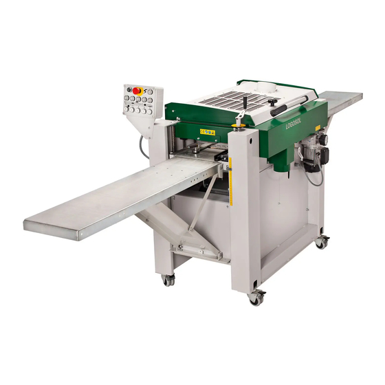
Page 8: Overall View
Overall View... -
Page 10: Machine Description
Ensure that there is no risk of being dazzled by the light. clamps both at the planer end and the chip extractor end. Use the Flexi Hose from Logosol (length: 3 m, ref. no. 7000-000-1015), which has a smooth inside improving the flow. -
Page 11: In- And Out-Feed Tables
(own-made) fence for jointing operation with the first side cutter is to be mounted on the in-feed table. (Logosol supplies a ready-made fence for jointing operation, which you fit in the machine’s fence screw plates, see Accessories.) -
Page 12: Control Panel
Control Panel The control panel is not mounted when you receive the machine, but lies inside the machine on the machine table. The control panel is to be mounted on the in-feed side of the machine. In the parts box, which also lies on the machine table, there are two bolts that should be used for mounting the panel. -
Page 13: Lower Horizontal Cutter
(4 mm Allen) (C) next to the cutter’s knife slot. Use a 4 mm Allen key (supplied). The knives should protrude 1 mm in order to fit against moulding knives from Logosol. The lower cutter is located in the machine table on the in- Check the knife level in the cutter head by placing a piece feed side of the machine. -
Page 14: Upper Horizontal Cutter
The grinding angle should be 38°. You can order a grinding machine from Logosol for regrinding planing and moulding knives (Tormek grinder ref. no. 7010-000-1000, Jig for planing knives ref. no. -
Page 15: Moulding Knives In Upper And Lower Cutters
Moulding Knives in the Lower and Upper If there is not enough play in the bearing housings for the cutter to be adjusted, the machine table has to be adjusted Cutter (see p.22). Adjust the planing knives so that they are on a level and Before opening the planer’s cover, ensure that the power is disconnected and that the cutter heads are not rotating. -
Page 16: Side Cutters
Side cutters Removing the side cutters Cutter 2 (right side, stationary cutter): Using a 30 mm spanner Before opening the planer’s cover, ensure that the power is (supplied) and an adjustable spanner, loosen the nut on the disconnected and that the cutter heads are not rotating. Use spindle. - Page 17 You can groove are facing each other, i.e. they are at the same height order a grinding machine from Logosol for regrinding planing measured from the machine table. and moulding knives (Tormek grinder ref. no. 7010-000-1000, jig for moulding knives ref.
- Page 18 Check that the test board has contact with both fences, and tighten the lock nuts of the back fence. Logosol’s setting rule (art. no. 7502-001-0405) facilitate adjustments of the stationary cutter’s fences. Make sure that all screws that hold the fences are firmly tightened, and that the cutter head can rotate freely.
- Page 19 Tip: If the board does not follow the fences, the cause may be To set the pressure rollers, you loosen the Allen screw (using that the back fence is not on the right level with the cutter, that a 6 mm Allen key) that secures the L bracket on the carriage the fences are not parallel to each other, or that the fences are of the movable cutter.
-
Page 20: Belt Transmissions
Belt Transmissions Belt transmissions, lower and upper cutter: The motor of the upper cutter is suspended on a metal pipe (29). Ensure that the power is disconnected before opening Most of the belt tension is produced by the weight of the motor. any protective covers or carrying out any servicing on the The pipe is fixed in the chassis by bolts that goes through its machine. -
Page 21: Feeder
Feeder Adjusting the feeding speed The stepless feeding speed can be adjusted by turning the The feeder of the machine consists of a three-phase motor that knob on the planetary gear. If the knob is turned clockwise runs the out-feed roller via a planetary gear. The planetary gear the feeding speed is increased;... -
Page 22: Levelling The Machine Table
Levelling the machine table Turn each of the threaded bars until the cutter head touches the block along its entire length (alternatively, measure between the table and the cutter head). Each threaded bar Levelling the machine table is a serious and complicated has to be turned a little at a time to avoid the table getting operation. -
Page 23: Accessories
Accessories Magnetic adjuster Well-tried equipment for quick and Logosol has a wide range of accessories for PH 260. The accurate adjustment of planing accessories are also presented in Logosol’s Moulding Knives knives in the upper and lower cutter. Catalogue and Product Catalogue. - Page 24 7010-000-1005 Line laser Jig for moulding knives: Ref. Logosol can supply a line laser that facilitate the lining up of the no. 7010-001-1012 workpiece before it is fed through the machine. The machine must then be fixed to the floor. The laser can be fitted to the ceiling in the room.
-
Page 25: Maintenance
Logosol’s Low Friction Agent (ref. no. 7500-001-5050) is carriage. especially suited for wood processing machines. Avoid getting lubricant on the feed rollers. -
Page 26: Knives; Planing/Moulding With Logosol Ph 260
18 % for metal processing. The trend goes towards having 18 % of tungsten carbide in all cutting HSS tools. Logosol has for a long time used Grinding planing knives consisting of 18 % tungsten carbide and, due... - Page 27 Grind the knife before it becomes dull height of max. 120 mm. Logosol offers a wide range of standard knives, and custom-made knives can be ordered.
-
Page 28: Planing/Moulding Tips
Otherwise the room marks in the planed surface of the workpiece. will quickly become cold. Boards that are too warped should be run through a jointer or be dimension planed in the PH260, the DH410 or the SH230 before the final machining. - Page 29 • Be careful when adjusting the side fences. The back fence is Saving a moulding pattern to be level with the outermost cutting diameter of the cutter. If you have produced a moulding that you know you will produce The two fences should be parallel with each other and set in the future, it can be wise to take some measures before so that the board is fed slightly diagonally (totally about 5 removing the mounted knives.
-
Page 33: Troubleshooting
The takeoff of the knives in the upper Set the takeoff of the planing knives correspond to the setting of the scale. cutter are set incorrectly. to 1 mm, using Logosol’s setting The pointer of the height scale is set block (ref. no. 7500-000-1020) or incorrectly. - Page 34 1 mm (or, if necessary, The moulding knives are ground some tenth of a millimetre more) incorrectly. using Logosol’s setting block (ref. no. 7500-000-1020) or a magnetic adjuster for the upper cutter (ref. no. 7500-001-0050). Regrind the moulding knives so that...
- Page 35 Clean feed rollers with accumulated in the grooves of the Logosol’s Machine Cleaner (ref. no. feed rollers and on the out-feed 7500-001-5000). roller. Increase feeding pressure The pressure of the feed rollers is and make sure the feed rollers are too low.
- Page 36 The electrical system may only be opened by a qualified electrician: Ensure that all cables are correctly connected. The workpiece is fed jerkily through the The machine table is covered with Clean the table with Logosol’s machine. resin or rust. Machine Cleaner (ref.
- Page 37 Problem Possible Cause Remedy Rumbling or vibration in the upper or the The moulding knives are incorrectly Clean the cutter and mount the lower cutter. mounted. knives chip breakers The moulding knives or the planing correctly. Identical knives should knives are incorrectly ground. be mounted on opposite sides of The bearing is defect.
-
Page 38: Circuit Diagram, 400 V 3-Phase
Circuit diagram 400 V 3-phase CIRCUIT DIAGRAM PLANER/MOULDER, 240 V 3-PHASE, NO 424- ELSCHEMA PANELHYVEL PH260, 400 VOLT 3-fas, Nr 424- Earth Jord ELECTRIC BOX CONTROL PANEL ELSKÅP MANÖVERPANEL Lethal voltage! Faulty connection can result in a fatal accident. Note that only qualified electricians are... -
Page 39: Circuit Diagram, 230 V 3-Phase
Circuit Diagram 230 V 3-phase CIRCUIT DIAGRAM PLANER/MOULDER, 230 V 3-PHASE, NO 424- ELSCHEMA PANELHYVEL PH260, 230 VOLT 3-fas, Nr 424- Pe. Earth Pe, Jord ELECTRIC BOX CONTROL PANEL ELSKÅP MANÖVERPANEL Lethal voltage! Faulty connection can result in a fatal accident. -
Page 40: Circuit Diagram, 230 V 1-Fas
Circuit Diagram 230 V 1-phase CIRCUIT DIAGRAM PLANER/MOULDER, 230 V 1-PHASE ELECTRICAL DRAWING PH260, 230 VOLT 1-PHASE. Pe, EARTH ELECTRICAL MAIN BOX MANOUVER BOX Lethal voltage! Faulty connection can result in a fatal accident. Note that only qualified electricians are... -
Page 41: Technical Data
Directive: (89/392/EEG with the amendments 91/44/EEG, 91/368/EEG and 93/68/EEG). Feeder The manufacturer also declares that Logosol PH260 is 5 rollers run by a 0.18 kW motor via a chain transmission manufactured in accordance with (parts of) the following with the speed of approx. 6 m/min. (20 ft/min.). - Page 44 LOGOSOL Sweden Fiskaregatan 2 SE-871 33 HÄRNÖSAND Telefon 0611-182 85 Telefax 0611-182 89 info@logosol.se http://www.logosol.se...
Need help?
Do you have a question about the PH260 and is the answer not in the manual?
Questions and answers