Table of Contents
Advertisement
Quick Links
USER MANUAL
ORIGINAL USER MANUAL.
SKU 0458 395 5401
REV: 7
Read through the user manual carefully and make sure you understand its contents
before using the saw.
This user manual contains important safety instructions.
WARNING! Incorrect use can result in serious or fatal injuries to the operator or others.
LOGOSOL B751
BAND SAWMILL
EN
Advertisement
Table of Contents

Related Manuals for Logosol B751


Summary of Contents for Logosol B751
- Page 1 USER MANUAL ORIGINAL USER MANUAL. SKU 0458 395 5401 REV: 7 LOGOSOL B751 BAND SAWMILL Read through the user manual carefully and make sure you understand its contents before using the saw. This user manual contains important safety instructions. WARNING! Incorrect use can result in serious or fatal injuries to the operator or others.
- Page 2 We are very pleased that you have demonstrated your confidence in us by purchasing this sawmill and we will do our utmost to meet your expectations. LOGOSOL has been manufacturing sawmills since 1989, and in that time we have supplied approximately 50,000 machines to satisfied customers the world over.
-
Page 3: Table Of Contents
B751 TABLE OF CONTENTS General information Description of the band sawmill Safety instructions Technical data Component parts Mounting the rail Setting: Rail Final assembly: rail Saw head Final saw head assembly Installation of the motor: see separate instructions Adjustment sequence... -
Page 4: General Information
Responsibility for correct assembly, commissioning and use of the band sawmill rests with whoever has assembled it and the people who use it. DESCRIPTION OF THE BAND SAWMILL B751 Forwards Back Page... -
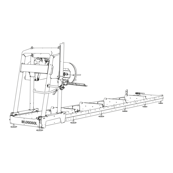
Page 5: Description Of The Band Sawmill
B751 DESCRIPTION OF THE BAND SAWMILL LOGOSOL B751 Saw carriage Reservoir, saw blade cooling Fuel tank Machine decal Lifting eyes Gauges, saw kerf setting Cover, band wheel Push handle/throttle control Crank, height setting Handle, saw blade tensioning Adjustable saw blade guard... -
Page 6: Safety Instructions
SAFETY INSTRUCTIONS KEY TO SYMBOLS Always wear approved hearing protection WARNING! This symbol means that you when working with the machine. Even have to take particular care. It is always brief exposure to high frequency noise accompanied by information on the can damage your hearing. - Page 7 B751 SAFETY INSTRUCTIONS THE BAND SAWMILL’S SAFETY WORK SITE EQUIPMENT WARNING! Never operate a band sawmill with a combustion engine in a closed or poorly WARNING! Never use the machine ventilated area. Doing so can cause death by if the safety equipment is defective..
-
Page 8: Technical Data
TECHNICAL DATA LOGOSOL B751 RAIL COMPONENT Rail length, standard 5.75 m Rail length, extension 1140 mm Track width 800 mm Overall width 850 mm Height 230 mm Weight (5.75 m rail) 195 kg SAW CARRIAGE Length 900 mm Width 1975 mm... - Page 9 B751 BOLTS/NUTS Definition of the fasteners on following pages. Shoulder bolt Allen screw Cross screw Allen screw (partially threaded) Hex bolt Slotted screw Set screw Hex bolt (partially threaded) Hex nut Flange screw Flange nut Flange screw (partially threaded) Carriage bolt...
-
Page 10: Component Parts
COMPONENT PARTS 01-00306 03-01959 8210-001-0020 03-01964 02-00247 03-01979 9039-001-0005 12 x 10 x 03-01957 01-00232 03-01968 03-01969 8400-005-0005 03-01970 8400-005-0010 03-01985 8400-005-0020 03-01983 8400-005-0030 03-01967 8200-005-0200 03-01966... - Page 11 B751 COMPONENT PARTS 8400-005-0005 100 x M8x20 9018-346-0820 110 x 9214-352-0008 8400-005-0010 9291-021-0180 M8x25 9018-346-0825 12 x M8x12 9018-346-0812 9018-346-1860 M8x30 8400-005-0020 9291-021-0140 24 x 9210-260-1600 M6x35 9018-346-1380 8400-005-0030 9214-352-0006 9291-020-0005 03-01464 9026-015-0002 03-01465 9029-011-0001 8200-005-0200 03-01772 03-01773 03-01982...
-
Page 12: Mounting The Rail
RAIL ASSEMBLY Work on a surface that is as flat as possible, as this will make it easier to set the rail. WARNING! Heavy lifting! Risk of injury. WARNING! Risk of crushing injury. Wear protective gloves and handle the motor Two people are always required to help with carefully when placing it on the motor shelf. - Page 13 B751 Assemble the bed fittings with the log bed. Note that it is important to install the fittings as illustrated. 8400-005-0010 M8x20 Repeat the installation procedure on the other log beds. 8400-005-0010 12 x M8x20 12 x...
- Page 14 Assemble the rail sections with the log bed. Note that these must only be fitted in the lower hole and tightened loosely. 8400-005-0010 M8x20 Assemble the rail sections with the log bed. Note that these must only be fitted in the lower hole and tightened loosely. 8400-005-0010 M8x20...
- Page 15 B751 Assemble the rail sections with the log bed. Note that these must only be fitted in the lower hole and tightened loosely. 8400-005-0010 M8x20 Assemble the rail sections with the log bed. Note that these must only be fitted in the lower hole and tightened loosely.
- Page 16 Assemble the rail sections with the log bed. Note that these must only be fitted in the lower hole and tightened loosely. 8400-005-0010 M8x20 Fit the inner end cap plates to the outer ones. Note that the two shock absorbers must be mounted in the upper corners.
- Page 17 B751 Fit the end piece to the end of the rail. Mount only in the lower holes. Then repeat the installation procedure at the other end of the rail. 8400-005-0010 M8x20 Assemble the pieces of rail. Start with a short piece of rail (3 holes) to be placed at the end of the rail.
- Page 18 Fit the next two pieces of rail. Tighten the screw joints loosely. 8400-005-0010 12 x M8x20 12 x Fit the last three pieces of rail. Note that the short piece must be located at the end of the rail. Tighten the screw joint loosely. 8400-005-0010 15 x M8x20...
- Page 19 B751 To complete the assembly of the rail pieces, repeat the assembly steps (10-12) on the other side of the rail. Fit the adjusting nuts on the feet. 8400-005-0030 12 x 12 x Fit the feet to the rail and secure them using the locking nuts.
-
Page 20: Setting: Rail
Well done! Now work continues on setting the rail SETTING: RAIL (Tools are not supplied with the sawmill.) Read through all the setting instructions before starting work, then follow the instructions step by step as you work. Now it is time to adjust the rail. The aim is to make both sides of the rail as flat as possible. - Page 21 B751 SETTING: RAIL Start setting the rail by securing a cord between the alignment holes in the ends of the rail. Position 2 nuts between the cord and the rail to act as a spacer. Make sure that the nuts are placed at the ends of the rail and lift the cord.
- Page 22 SETTING: RAIL IMPORTANT! Now aim and measure along the string to check that the distance This step is critical to sawmill between the string and the rail is consistent along its entire length. accuracy, so take care and The aim is to achieve even spacing over the entire length of the rail. spend extra time working To adjust the straightness, it may be useful to insert wedges under on this step.
-
Page 23: Final Assembly: Rail
B751 Well done! FINAL ASSEMBLY: RAIL Read through all the assembly instructions before starting assembly, then follow the instructions step by step as you work. The remaining installation work on the rail will now begin. Fit the log tensioning profiles on the log bed. - Page 24 FINAL ASSEMBLY: RAIL Fit the adjustment arm for the log support to the log bed. 8400-005-0010 8400-005-0020 8200-005-0200 M8x25 M8x11 Fit the log support in the log bed. Then repeat the installation procedure for the second log bed. Fit the spacers for the log support storage in the sides of the rail.
-
Page 25: Saw Head
B751 Well done! It is now time to mount the saw head on the rail. SAW HEAD The saw head is partly assembled when supplied. The rail bar tipping wheels must be installed as soon as the saw head has been placed on the rail. After installing... - Page 26 THE SAW HEAD INSTALLING THE SAW HEAD ON THE RAIL Lift the saw head into place on the rail. The saw head weighs 178 kg in total. Use a sling approved for the purpose and attach to the saw head’s lifting eyes. Lift the saw head using the appropriate lifting gear.
- Page 27 B751 THE SAW HEAD Fit the wheels and spacers to the anti- tip plate. Then repeat the installation procedure for the second anti-tip plate. 8400-005-0030 M6x35 Fit the anti-tip plate on the bogie tube. Use existing nuts from step 1. Then repeat the installation procedure for the other side of the machine.
-
Page 28: Final Saw Head Assembly
FINAL SAW HEAD ASSEMBLY The saw head is assembled on delivery of the sawmill, except for the motor and the handle and crank. Follow the instructions below to complete sawmill assembly before initial start-up. Assembly work begins with the crank and ends by connecting the throttle cable and installing the sawmill motor. Follow the installation instructions and take care with the assembly work. - Page 29 B751 FINAL SAW HEAD ASSEMBLY Insert the handle into the main post Secure the handle in place using the prefitted short fastening screws. M8x16 Secure the handle in place using the long fastening screws. Please note that the inner nut must be positioned so that the hex head of the bolt aligns with the outside of the tube.
- Page 30 FINAL SAW HEAD ASSEMBLY Tension the chain using the chain tensioner. Fit the crank. Liberally grease the crank threads.
-
Page 31: Installation Of The Motor
B751 INSTALLATION OF THE MOTOR: SEE THE SEPARATE USER MANUAL It is now time to fit the engine. The instructions for fitting the engine are supplied in a separate attachment: see the instructions for the engine you will be working with. -
Page 32: Adjustment Sequence
ADJUSTMENT SEQUENCE Read through all the set-up instructions before starting to set up, then follow the instructions step by step as you work. IMPORTANT! It is important to adjust the saw head before starting to ensure satisfactory sawing and the correct functioning of the sawmill. Carefully follow the adjustment sequence! Certain adjustments affect other machine settings. - Page 33 B751 ADJUSTMENT SEQUENCE ADJUST THE RAIL HORIZONTALLY It is important that the rail is completely level so as to ensure that it functions well. We have previously set the straightness of the rail in longitudinal direction. Now the rail has to be adjusted horizontally along the short side.
- Page 34 Loosen the locking screw ADJUSTMENT SEQUENCE LONGITUDINAL BLADE POSITION The longitudinal blade position over the wheels is adjusted using the horizontal adjusting screws, i.e. the screws on the outside of the axle mountings. The lock nut must be opened first when adjusting the blade position.
- Page 35 B751 ADJUSTMENT SEQUENCE Measurement point 2 Measurement point 1 X mm X mm ADJUST THE SAW BLADE PARALLEL TO THE LOG BEDS It is important for the saw blade to be parallel to the log beds to ensure the proper functioning of the sawmill. Measure the distance vertically down from the blade to the log bed, then note down the values.
- Page 36 ADJUSTMENT SEQUENCE TENSION THE BLADE GUARD ARM It is important for the blade guard arm to move smoothly in the attachment plate to ensure proper functioning of the sawmill. Release the Allen head bolt on the blade guard plate, then push the wheel downwards using a screwdriver as illustrated.
- Page 37 B751 ADJUSTMENT SEQUENCE Measurement point 1 ADJUST THE BLADE SO THAT IT IS PARALLEL TO THE RAIL It is important for the saw blade to be parallel to the rail to ensure the proper functioning of the X mm sawmill. Place a straightedge on the saw blade, as close to one of the blade guide rollers as possible.
-
Page 38: Other Settings
OTHER SETTINGS Read through all the set-up instructions The following settings are important for before starting to set up, then follow the satisfactory operation of the sawmill, instructions step by step as you work. but they do not affect one another and so there is no need to implement them in any particular order. - Page 39 B751 OTHER SETTINGS LOG SUPPORT It is important for the relationship between the log bed and the log support to be perpendicular to ensure the proper functioning of the sawmill. This is adjusted by turning the adjustment handle in the lower part of the log support.
- Page 40 OTHER SETTINGS SET THE CRANK SPRING Tighten the lock nut in order to tension the spring so that the handle snaps back easily and locks in the crank pulley. When the handle is working properly, bend the lock washer to secure the lock nut in position.
-
Page 41: Sawmill Features
B751 SAWMILL FEATURES CRANK FEATURE The crank used to move the saw head up and down is spring-loaded and must be pushed against the machine to release the locking mechanism while raising or lowering the saw head. 360 = 1 inch The crank locking mechanism is divided into eight positions on a single rotation. - Page 42 RELATIVE SCALE, BLADE- COMPENSATED mm/Inch SAWMILL FEATURES GAUGE, MM/INCH GAUGE FEATURE The sawmill has two gauges: a millimetre gauge showing the distance between the log bed and the saw blade, and a blade-compensated gauge LAST CUT INDICATOR showing a range of different board thicknesses in inches.
-
Page 43: Wiring Diagram
B751 SAWMILL FEATURES WATER COOLING Water cooling is controlled by means of a lever in the side panel in front of the operator. The lever is perpendicular to the panel in its initial position. The lever is pulled backwards to turn on the water flow. -
Page 44: Use
WARNING! Risk of flying fragments from dirty logs. WARNING! Cutting tools: Always stand Always inspect the logs so that there are no behind the saw carriage and keep both hands objects wedged in the bark before sawing. on the handles when operating the machine. Never stand in front of the saw carriage or Load and turn logs carefully. - Page 45 B751 Hard knots may cause deviations in the outcome • the bandsaw blade runs clear of the log of the sawing. supports and log clamp • the rail is clear of debris, dirt, etc. • the workpiece is secured in place BEFORE EACH USE: •...
-
Page 46: Chip Collection
STORAGE MOVING THE BAND SAWMILL The bandsaw blade must be removed from the WARNING! Risk of entrapment. machine and stored out of reach of children and other persons, even if the machine will not be used When lifting and moving machine parts, keep for just a short time. -
Page 47: Start / Stop
B751 STARTING AND STOPPING STARTING 1. Open the fuel valve by moving the slide control to the right to the "ON" position. 2. To start a cold engine, set the choke to closed position (lever to the left). To start a warm engine, leave the choke in open position (lever to the right). -
Page 48: Operating Instructions
OPERATING INSTRUCTIONS LOG PILE When loading a log: 1. Place the saw carriage as far back on the rail Do not make the log pile more than 1 m high. as possible (its starting position). Logs that are contaminated with earth, sand or clay 2. - Page 49 B751 OPERATING INSTRUCTIONS OP:1 Safety device at the front of the log pile Logs The right side of the Safety wedge at the rail must be clear rear of the log pile Rail Log table OP:2 Detachable ramp Figure 2...
- Page 50 ADJUSTING THE SAW KERF The position of the saw head can be adjusted in increments to set the depth of the cut. The B751 PRO band sawmill comes equipped with 1”, 1 1/2”, 1 3/4” and 2” gauges with saw kerf compensation as standard.
- Page 51 B751 OPERATING INSTRUCTIONS 6. Secure the log using the log clamps. Adjust the 13. Placing both hands on the push handle, carefully height of the log clamps, but do not position them push the saw carriage forward until the saw blade so high that the saw blade may come into contact starts to cut into the log.
-
Page 52: Maintenance
OPERATING INSTRUCTIONS M AINTENANCE MAINTENANCE Turn the log through 90° so that one of the freshly sawn sides rests against the log supports, then The periodic maintenance on the machine that clamp the log in position. Now you can make the is expected to be performed by the operator is third kerf and obtain finished boards. - Page 53 B751 MAINTENANCE HANDLING SAW BLADES and to ensure problem-free ownership. Lubrication must be carried out: WARNING! Cutting tools: Incorrect handling of • Immediately after assembly and before bandsaw blades may result in potentially fatal starting to use the sawmill. injuries. Saw blades are extremely sharp.
- Page 54 MAINTENANCE CLEANING THE BAND SAWMILL RAIL FLATNESS Clean the band sawmill after every shift. Brush out Check the balance of the rail before every shift, any wood chips or sawdust inside the band wheel particularly in winter when frost may affect the guard and on and around the rail.
-
Page 55: Troubleshooting
B751 TROUBLESHOOTING SCHEDULE PROBLEM/SYMPTOM PROBABLE CAUSE ACTION The saw blade quickly loses its edge • Dirty logs • Avoid dragging the logs over the ground. • The saw blade is worn out • Debark the log at the point where the saw blade is to cut •... -
Page 56: Machine Declaration
Fiskaregatan 2 Tel. +46 611 18285 871 33 Härnösand hereby declares that Logosol B751 hereby declare that the Logosol B751mobile band sawmill has been manufactured in conformity with: Supply of Machinery (Safety) Regulations has been manufactured in conformity with: 2008...
Need help?
Do you have a question about the B751 and is the answer not in the manual?
Questions and answers