Advertisement
Quick Links
Advertisement

Subscribe to Our Youtube Channel
Related Manuals for Cookology CYL351BK


Summary of Contents for Cookology CYL351BK
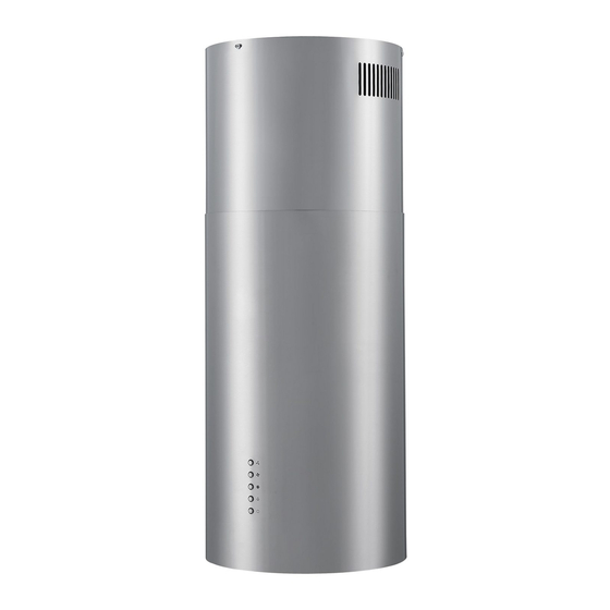
- Page 1 CYL351BK & CYL351SS CYL351WH & CYL351COP Cooker hood Instruction manual...
-
Page 2: Table Of Contents
CONTENT 1……………………………………….Notice 2……………………………………….Feature 3………………………………………..Installation 4………………………………………..Notice of installation 5………………………………………..Safety Warning 6…………………………………………Speed adjustment 7…………………………………………Maintenance 8………………………………………….. Abnormity and Solution... -
Page 3: Notice
1.Notice This appliance can be used by children aged from 8 years and above and persons with reduced physical, sensory or mental capabilities or lack of experience and knowledge if they have been given supervision or instruction concerning use of the appliance in a safe way and understand the hazards involved. - Page 4 The instructions shall state the substance of the following: – there shall be adequate ventilation of the room when the range hood is used at the same time as appliances burning gas or other fuels (not applicable to appliances that only discharge the air back into the room);...
- Page 5 – CAUTION: Accessible parts may become hot when used with cooking appliances. The installation instructions shall include the substance of the following: – the air must not be discharged into a flue that is used for exhausting fumes from appliances burning gas or other fuels (not applicable to appliances that only discharge the air back into the room);...
- Page 6 discharge of air have to be fulfilled. The installation instructions for range hoods with accessible metallic enclosures of class II construction shall include details that indicate the location and maximum permitted lengths for any fixing or mounting screw or other fixing device that penetrates into the range hood to attach an accessory such as a facia or duct fitting.
-
Page 7: Feature
substance of the following warning. Warning: Failure to install the screws or fixing device in accordance with these instructions may result in electrical hazards Feature 1. The cooker hood uses high quality materials, and is made with a streamlined design. 2. - Page 8 If you have an outlet to the outside, your cooker hood can be connected as below picture by means of an extraction duct. (enamel, aluminum, flexible pipe or non-flammable material with an interior diameter of 150mm) 1. Before installation, turn the unit off and unplug it from the outlet. 2.
- Page 9 5. Calculate the length of angle iron according 1.To connect the angle iron and bracket with 18 pcs M4X10 screws ,M4 nut and washer. (the overlap between angle iron should more than 100mm) See pic 3. 6. Using 6 pcs M4X10 screws to fix the angle iron on the cooker hood housing, and install the expansion pipe.
-
Page 10: Notice Of Installation
9. See Pic 8, put up the unit, and take the expansion pipe out of ceiling. And then using 6 pcs M4X10 screws, M4 nut and washer fix the angle iron of unit to the hanging board. 10. see Pic 9. Undrawn the inside chimney and use 3 pcs ST4X8 screws to fix the inside chimney on hanging board. -
Page 11: Safety Warning
4. After installation, make sure that the extractor is level to avoid grease collection at one end. 5. Safety Warning In certain circumstances electrical appliances may be a danger hazard. Keep electrical appliances out of reach from Children or infirm •... -
Page 12: Speed Adjustment
6. Speed adjustment Electronic button There are five buttons: (Low), (Mid), (High), (Light), (Power).See Pic above. 1. After connecting to power, indicator light will lit on, all the output close and the hood will enter standby mode. The indicator light will be off automatically after reminding if no operation. -
Page 13: Maintenance
6. Press the (low) button one time, motor runs on low speed, the indicator light of low button and power button will beam. Press low button again and the motor will stop. Indicator light of low button and power button will be off,and recycle by circle. 7. - Page 14 Attention! Keep the motor and other spare parts free from water, as this will cause damage to the appliance. Attention! Before cleaning the appliance please remember to cut off the power. 6. Changing and cleaning the anti-grease filters -Removing the filters as the instruction of picture. You can clean the filter as below measure: Soak them for about 3 minute in hot water (40-50 degrees) with a grease-loosening detergent then brush it gently with a soft brush.
- Page 15 1)Remove the filters. 2)The carbon filters are located at either end of the motor. Turn the charcoal filters anti-clockwise until they are unscrewed. 3)Apply reverse procedure to install the charcoal filter NOTE: • Make sure the filter is securely locked. Otherwise, it would loosen and cause dangerous.
-
Page 16: Abnormity And Solution
– Dimensions: Abnormity and Solution Fault Cause Solution The leaf blocked Get rid of the blocking The capacitor damaged Replace capacitor Light on, but motor does not work The motor jammed bearing Replace motor damaged The internal with of motor off or Replace motor a bad smell from the motor Beside the above mentioned, check the following:... - Page 17 The body is not tightly Fixed the body tightly hanged Insufficient suction The distance between the Readjust the distance body and the gas top too long Too much ventilation from Choose a new place and open doors or windows resemble the machine The machine inclines The fixing screw not tight Tighten the hanging...
Need help?
Do you have a question about the CYL351BK and is the answer not in the manual?
Questions and answers