
Related Manuals for Extron electronics AXP 64 C AT


Summary of Contents for Extron electronics AXP 64 C AT
- Page 1 User Guide Audio Products Mixers and Processors AXP 64 C AT Audio Expansion Processor 68-2721-01 Rev. D 10 22...
- Page 2 Safety Instructions Safety Instructions • English WARNING: This symbol, , when used on the product, is intended to alert the user of the presence of uninsulated dangerous voltage within the product’s enclosure that may present a risk of electric shock. ATTENTION: This symbol, , when used on the product, is intended...
- Page 3 Copyright © 2013-2022 Extron. All rights reserved. www.extron.com Trademarks All trademarks mentioned in this guide are the properties of their respective owners. The following registered trademarks ( ® ), registered service marks ( ), and trademarks ( ) are the property of RGB Systems, Inc. or Extron (see the current list of trademarks on the Terms of Use page at www.extron.com):...
- Page 4 FCC Class A Notice This equipment has been tested and found to comply with the limits for a Class A digital device, pursuant to part 15 of the FCC rules. The Class A limits provide reasonable protection against harmful interference when the equipment is operated in a commercial environment.
- Page 5 Conventions Used in this Guide Notifications The following notifications are used in this guide: WARNING: Potential risk of severe injury or death. AVERTISSEMENT : Risque potentiel de blessure grave ou de mort. CAUTION: Risk of minor personal injury. ATTENTION : Risque de blessure mineure.
-
Page 7: Table Of Contents
Contents Dante Controller Configuration ....23 Introduction ..........1 Overview ............23 About this Guide ..........1 Downloading and Installing Dante Controller ..23 About the AXP 64 C AT ........1 Configuring the AXP 64 C AT Features .............. 2 in Dante Controller ..........24 AXP 64 C AT Application Diagrams...... - Page 8 Processors Configurable by SIS Commands ........38 Symbol Definitions ......... 39 Special Characters ........40 Command and Response Table for DSP SIS Commands ........40 Digital I/O SIS Commands ......... 42 Symbol Definitions ......... 42 Command and Response Table for Digital I/O SIS Commands ....... 42 Mounting the AXP 64 C AT ......
-
Page 9: Introduction
Introduction This section provides an overview of this guide and the features of the Extron AXP 64 C AT Audio Expansion Processor. Topics include: • About this Guide • About the AXP 64 C AT Features • • AXP 64 C AT Application Diagrams About this Guide This guide contains installation, configuration, and operation information for the Extron AXP 64 C AT Audio Expansion Processor. -
Page 10: Features
Features • Inputs — Six balanced or unbalanced mic/line level processed inputs, four with AEC, are provided on 3.5 mm, 3-pole captive screw connectors. • Phantom power — 48-volt phantom power is provided on the first four inputs. • Independent AEC — Four independent channels of high performance AEC, as well as selectable noise cancellation, are provided on the first four inputs. - Page 11 DSP Configurator Software — A powerful yet user-friendly PC-based software tool • can be used for managing all audio operations of the AXP 64 C AT. It enables complete setup and configuration of digital audio processing tools on the ProDSP platform. • Intuitive Graphical User Environment — The DSP Configurator Software features a Graphical User Environment that offers a clear view of all inputs, outputs, and audio processing blocks in a single window.
-
Page 12: Axp 64 C At Application Diagrams
AXP 64 C AT Application Diagrams Assistive Listening Network System Emitters Extron Extron AXP 64 C AT MPA 152 Plus Expansion Power Processor Ampli er Wireless Microphone Transmitters MPA 152 Plus 8Ω / 4Ω CLASS 2 IN G 01 02 IN G 01 02... - Page 13 INPUTS OUTPUTS ACTIVITY CLIP CLIP CONFIG SIGNAL SIGNAL DMP 128 DIGITAL MATRIX PROCESSOR GREEN - ACTIVE OVER System Emitters AMBER - STANDBY TEMP LIMITER / PROTECT SIGNAL XPA 4002 Figure 2. AXP 64 C AT Auditorium Application AXP 64 C AT • Introduction...
-
Page 14: Installation
Installation This section describes the front and rear panel features and the rear panel connections. It also provides procedures for installing the Dante Controller and DSP Configurator software. The following topics are discussed: • System Configuration Rear Panel Features and Cabling •... -
Page 15: Rear Panel Features And Cabling
IN G 01 02 IN G 01 02 IN G 01 02 IN G 01 02 POWER 1.0A MAX RESET AXP 64 C AT Power input Analog outputs Digital I/O ports AT ports Mic/line inputs Reset button Figure 3. AXP 64 C AT Rear Panel Power input —... - Page 16 ATTENTION: • Always use a power supply provided by or specified by Extron. Use of an unauthorized power supply voids all regulatory compliance certification and may cause damage to the supply and the end product. • Utilisez toujours une source d’alimentation fournie par Extron. L’utilisation d’une source d’alimentation non autorisée annule toute conformité...
- Page 17 ATTENTION: • Condenser microphones require phantom power. Dynamic microphones do not require power. • Les microphones électrostatiques nécessitent une alimentation fantôme. Les microphones dynamiques n’ont pas besoin d’alimentation. • Never set an unbalanced dynamic microphone to +48 V. Doing so may damage the microphone.
- Page 18 X .X DO NOT Connect Here 5-pole CSR Figure 7. Connecting a 5-pole Audio Connector AT ports — (see figure 3 on page 7) This four-port Gigabit switch with four RJ-45 Ethernet connectors supports digital audio transport (AT) and communications. Connect one or more AXP 64 C ATs to a device such as the DMP 128 AT to form a larger AXP 64 C AT system (see Creating a Physical Dante Network on page 12).
-
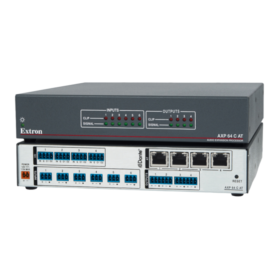
Page 19: Front Panel Indicators
OUTPUTS CLIP CLIP SIGNAL SIGNAL Extron AXP 64 C AT AUDIO EXPANSION PROCESSOR Figure 8. AXP 64 C AT Front Panel Power LED — This green LED blinks during boot-up. It lights steadily when the AXP 64 C AT is powered on and ready to operate. -
Page 20: Creating A Physical Dante Network
A daisy chain configuration can also be used. Each unit is connected to both the previous unit and the next unit in the chain (see figure 10). DMP 128 AT AXP 64 C AT #1 AXP 64 C AT #3 AXP 64 C AT #2... -
Page 21: Software Installation
Software Installation To configure and operate the AXP, use a PC running Microsoft Windows 10 or newer and the following software programs: • Dante Controller for Windows from Audinate is required to select and route AXP 64 C AT digital inputs and outputs to and from all connected Dante-compatible devices on the same network and to rename connected devices. -
Page 22: Downloading Dsp Configurator And Software
Downloading DSP Configurator and Software Visit www.extron.com to download and install the DSP software. NOTES: • Download the latest versions of software for your product. • An Extron Insider account is required to download and use the software. Mouse over the Download tab (see figure 11, ) at the top of the page. -
Page 23: Resetting
Resetting A recessed button on the rear panel (see figure 3, , on page 7) initiates a reset to factory values. Reset clears all processors, level controls, and mixers to the defaults and initiates a Dante controller reset (see Dante Controller Configuration starting on page 23). -
Page 24: Dsp Configurator Configuration
DSP Configurator Configuration This section contains information on configuring and operating the AXP 64 C AT using the DXP Configurator software. • AXP 64 C AT Operation • DSP Configurator Main Workspace • Connecting to DSP Configurator • Menu Bar • Accessing the DSP Configurator Help File AXP 64 C AT Operation You can create a complete configuration for the AXP 64 C AT using the DSP Configurator software. -
Page 25: Accessing The Dsp Configurator Help File
Accessing the DSP Configurator Help File DSP Configurator comes loaded with a context-sensitive help file that can be accessed by clicking the help icon ( ) in the top right corner of any dialog box in DSP Configurator. Alternatively, click Help > Contents in the menu bar at the top of the main workspace, or press <F1>... -
Page 26: Menu Bar
Menu Bar File The File menu offers the standard Windows File Menu options such as New, Open, Save, Save As, Recent Files, and Exit, along with three operations that are specific to Extron devices. Those operations are: • Export Single Device — Saves the currently selected device in Device Manager as a configuration file. -
Page 27: Tools
Tools Configure Digital I/O — Opens the Configure • Digital I/O dialog box to assign actions and modes to the digital inputs and outputs. • Connect/Disconnect from Device — In Emulate Connect to Device is listed and opens the mode, Connect to Device dialog box. -
Page 28: Presets Drop-Down List
Presets Drop-Down List Select the Presets drop-down list (see the image at the right) to view and apply presets saved in the current configuration file or on a device connected in Live mode. Presets with an asterisk next to them are on the AXP 64 C AT, but not in the current configuration file. - Page 29 To connect via RS-232: • Click the RS-232 tab in the dialog box. Select the Com port the device is connected to on the host PC from the Com Port drop-down list ( Figure 16. Connect to device... When a connection with a device is established, the Synchronize with Device dialog box opens (see the top image at the right).
- Page 30 Exit Live Mode and Enter Emulate Mode Click the Emulate button in the DSP Configurator menu bar. Alternatively, select Tools > Disconnect from Device or press <F6> on the keyboard. Click OK to confirm. Emulate Mode While in Emulate mode, DSP Configurator is functioning in an “offline” state. Changes made to the configuration file are not applied to a AXP 64 C AT.
-
Page 31: Dante Controller Configuration
• Overview AXP 64 C AT devices are equipped with an AT (Extron Audio Transport) bus and use Dante technology to provide high performance digital audio networking over standard TCP/IP networks. Dante allows audio channels to be transported across a switched Ethernet data network while meeting the quality requirements of professional audio. -
Page 32: Configuring The Axp 64 C At In Dante Controller
Existing subscriptions are removed when a device is renamed. • Il est essentiel qu’un appareil Dante soit nommé avant l’établissement des abonnements audio avec d’autres appareils. Les abonnements existants sont supprimés lorsqu’un appareil est renommé. AXP 64 C AT • Dante Configuration and Operation... -
Page 33: Dante Controller Naming Conventions
There are two MAC addresses listed on the rear panel of a AXP 64 C AT, one for the LAN port and one for the Dante interface. The Dante interface MAC address is listed beneath the LAN port MAC address. AXP 64 C AT • Dante Configuration and Operation... - Page 34 NOTE: The device name assigned in Dante Controller only applies to the Dante interface and does not affect the device name recognized in DSP Configurator. Figure 21. Rename Device Confirmation Dialog Box AXP 64 C AT • Dante Configuration and Operation...
-
Page 35: Renaming A Receiver Or Transmitter
Expanded Device View — Input and Output Names To simplify setup and operation of large AXP 64 C AT systems, rename the TIP: receiver and transmitter channels to better indicate the source at the transmitters or receivers. AXP 64 C AT • Dante Configuration and Operation... - Page 36 Press <Enter> on the keyboard to confirm the name, or click another channel text box. Repeat steps 4 through 6 to rename additional receiver or transmitter channels. When finished renaming receivers and transmitters, close the Device View dialog box. AXP 64 C AT • Dante Configuration and Operation...
-
Page 37: Finding A Dante Device Ip Address
EXP outputs. The AXP 64 C AT input channels are Dante receivers because they receive digital audio signal from the Dante network that can then be routed and mixed into the AXP 64 C AT mix AXP 64 C AT. AXP 64 C AT • Dante Configuration and Operation... -
Page 38: Dante Routing Operation
The Dante Controller - Network View screen opens (see figure 25). Dante Controller auto-discovers Dante devices on the network and advertises itself to allow other Dante-enabled devices to communicate with it. Transmitters connect to receivers using the subscription AXP 64 C AT. AXP 64 C AT • Dante Configuration and Operation... -
Page 39: Disconnecting Inputs From Outputs
Ethernet cable connecting the PC to the Dante network and restart Dante Controller. This can be enough for the software to reacquire the Dante network. If the problem persists, perform the following troubleshooting procedures in the order listed. AXP 64 C AT • Dante Configuration and Operation... -
Page 40: Simplifying The Network For Troubleshooting
Enable DHCP on the remaining network connection. This forces the computer to acquire an IP address from the Dante interface. NOTE: A DHCP server must be on the network for DHCP to function correctly. AXP 64 C AT • Dante Configuration and Operation... -
Page 41: Restarting Dante Controller
Click the Help icon in the upper-right corner of the Network View screen (see • figure 28, • Select Help, then Contents Shift+F1 from the list ( Press the <F1> key on the computer keyboard for online help or <Shift+F1> for offline • help. AXP 64 C AT • Dante Configuration and Operation... -
Page 42: Sis Configuration And Control
SIS Configuration and Control Extron SIS (Simple Instruction Set) commands can be issued from a host computer to remotely perform certain configuration and control functions on the AXP 64 C AT. This section describes the Ethernet connection through which these commands are issued to the AXP 64 and the commands. -
Page 43: Using Sis Commands
On the Device Info screen, locate the name of your AXP. The IP address is in the Primary Address column (see the example in figure 30, Figure 30. AXP IP Addresses on the Dante Controller Device Info Screen Connect the AXP to the control computer using a host communication utility such as Extron DataViewer (available at no charge from www.extron.com). -
Page 44: Using The Command And Response Tables
Using the Command and Response Tables SIS commands consist of a string (one or more characters per command field). No special characters are required to begin or end a command sequence. When the AXP 64 C AT determines a command is valid, it executes the command and sends a response to the host device. -
Page 45: Special Characters
Special Characters The HTML language reserves certain characters for specific functions. The device does not accept these characters as part of preset names, the device name, or locally created file names. The AXP 64 C AT rejects the following characters: + } ~ , @ = ‘ ’ [ ] { } < > “ ” | \ ? ; : {space} (Spaces are permitted in names.) Command and Response Table for Basic SIS Commands ASCII Command... -
Page 46: Processors Configurable By Sis Commands
Processors Configurable by SIS Commands The following diagram shows the specific DSP processors that can be configured via SIS commands (see the DSP Configurator Help File for details on the entire signal flow). Figure 31. DSP Processors Addressable via SIS Commands The DSP Configurator program window contains six channels. -
Page 47: Symbol Definitions
Symbol Definitions CR/LF (carriage return/line feed) (hex 0D 0A) Carriage return (no line feed, hex 0D) Space character • Escape key (hex 1B) Gain, trim, or attenuation block AT Output Gain Input Gain (Post-processed) Value Value Input 1 gain 40000 Output 1 gain 40100 Input 2 gain... -
Page 48: Special Characters
Special Characters The HTML language reserves certain characters for specific functions. The device will not accept these characters as part of preset names, the device name, passwords, or locally created file names. The AXP 64 C AT rejects the following characters: + } ~ , @ = ‘ ’ [ ] { } < > “ ” | \ ? ; : {space} (Spaces are permitted in names.) Command and Response Table for DSP SIS Commands ASCII Command... - Page 49 ASCII Command Response Command Additional Description (Host to Processor) (Processor to Host) Input Type Select input type X* ] Ds D Select input type block . For = analog = digital Polarity Set signal polarity X( ] Ds P Set signal polarity to block .
-
Page 50: Digital I/O Sis Commands
Digital I/O SIS Commands The digital I/O SIS commands let you view the status of the digital input and output ports. These ports can be configured via the DSP software from the Configure Digital I/O dialog box, which you can open by selecting Configure Digital Inputs from the DSP Tools menu. -
Page 51: Mounting The Axp 64 C At
Reliable earthing (grounding) — Maintain reliable grounding of rack- • mounted equipment. Pay particular attention to supply connections other than direct connections to the branch circuit (such as the use of power strips). AXP 64 C AT • Mounting the AXP 64 C AT... -
Page 52: Consignes Ul Pour Le Montage En Rack
Attach the four rubber feet to the bottom of the AXP in the four corners and place the unit on furniture as desired. To mount the AXP 64 C AT using an Extron mounting kit, see the instructions provided with the kit. AXP 64 C AT • Mounting the AXP 64 C AT... - Page 53 Extron Warranty Extron warrants this product against defects in materials and workmanship for a period of three years from the date of purchase. In the event of malfunction during the warranty period attributable directly to faulty workmanship and/ or materials, Extron will, at its option, repair or replace said products or components, to whatever extent it shall deem necessary to restore said product to proper operating condition, provided that it is returned within the warranty period, with proof of purchase and description of malfunction to: USA, Canada, South America,...
Need help?
Do you have a question about the AXP 64 C AT and is the answer not in the manual?
Questions and answers