Table of Contents
Advertisement
Quick Links
AXP 50 C AT • Setup Guide
Disconnect Power and Mount the AXP 50 C AT
Disconnect power to the AXP 50 C AT and turn off all devices that will be connected to it. The AXP 50 C AT is housed in a half
rack width, 9.5 inch deep, 1U high metal enclosure that can sit on a table with the provided rubber feet, or mount underneath a
conference table, inside a credenza, or anywhere microphones or other sources are located. Select a suitable mounting location,
then choose an appropriate mounting option.
Make all external device connections before applying power.
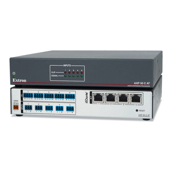
AXP 50 C AT Rear Panel
Figure 1.
A
12 VDC power input.
B
Five 3.5 mm, 4-pole captive screw connectors for
digital I/O trigger and tally back.
C
Five 3.5 mm, 3-pole captive screw connectors for
analog mic or line audio input.
Connections
B
Digital I/O connectors — Five connectors associated with the mic/line inputs provide digital input
and output ports designed to connect to microphones with logic circuits. Each has an input (IN) and
two output (O1 and O2) ports. The input port can enable mic mute from a remote source. The two
output ports can provide tally back to the mic LEDs to indicate mic status.
C
Mic/Line 1-5 input connectors — Connect up to five balanced or unbalanced microphone or
mono line level devices using the 3-pole, 3.5 mm captive screw connectors. Wire as shown below.
Audio Input Wiring
Tip
Ring
Sleeve
Balanced Input
NOTE:
An input can be analog or digital. Each channel can select either the associated rear panel analog input or
the AT digital channel input assigned by Dante Controller (see
D
AT port connectors — A 4-port Gigabit switch with RJ-45 connectors for digital audio transport and communications.
Connect one or more ports to a LAN using standard CAT cable. Connect one or more AXP 50 C ATs to a DMP 128 AT to form
a larger matrix system (see
Audio Output Wiring
E
Reset button — The reset button can return the AXP 50 C AT to a default state, see ("AXP 50 C AT Hardware Reset Mode" in
the AXP 50 C AT User Guide).
Tip
Ring
Sleeve
Balanced Output
Tip
Sleeve
Unbalanced Input
Creating a Physical Dante Network
Tip
NO Ground Here
Sleeve
Unbalanced Output
ATTENTION:
For unbalanced audio outputs,
This guide provides basic instructions for an experienced technician
to install the AXP 50C AT Audio Expansion Processor. For additional
information and specifications, see the AXP 50 C AT product page at
www.extron.com.
D
Four RJ-45 Ethernet connectors. The ports are used for both
digital audio and control.
E
Reset button.
Dante Operation
on page 8).
Product Category
3 "
(5 mm) MAX.
16
Do not tin the wires!
Digital I/O Wiring
on page 9).
I
G
O1
O2
1
Advertisement
Table of Contents

Related Manuals for Extron electronics AXP 50 C AT


Summary of Contents for Extron electronics AXP 50 C AT
- Page 1 Select a suitable mounting location, then choose an appropriate mounting option. Make all external device connections before applying power. AXP 50 C AT Rear Panel Figure 1. 12 VDC power input.
-
Page 2: Control Connection
AXP 50 C AT • Setup Guide (Continued) Control Connection figure 1 LAN — Using a standard Ethernet cable, connect to a network via one of the four AT ports (see on page 1). The control device must be connected to the same network. One of the four Ethernet ports can be dedicated as a control connection. -
Page 3: Power Supply Connection
Product Category Power Supply Connection ATTENTION: • Always use a power supply provided by or specified by Extron. 12 VDC power input – Connect the provided Use of an unauthorized power supply voids all regulatory 12 VDC power supply to the rear panel captive screw compliance certification and may cause damage to the supply connector (see figure 2) and plug in the power cord. - Page 4 Dante Controller for Windows Download Both software applications are available from the Extron Electronics web page at www.extron.com. From the Extron Electronics web page at www.extron.com, enter AXP 50 C AT in the search field and press <Enter>. The AXP 50 C AT product page opens.
-
Page 5: Dante Network Setup
Product Category Click Download. Save the file to your desktop (or other known location). If the Download Center page has closed, repeat step 1 and step 2. The Download Center page opens. Click DSP Configurator. Fill in the required fields, then click Download. Save the file to your desktop (or other known location). - Page 6 AXP 50 C AT • Setup Guide (Continued) From the toolbar, select Device>Device View. The Dante Controller - Device View dialog opens. Select your device from the (Select a Dante Device...) drop-down list. AXP50- 063f70 AXP50-063f70 AXP50-Podium AXP50-Lecture Hall AXP50-ConfRm 01 AXP50-ConfRm 02 DMP128-Rack #1 DMP128-Lecture Hall DMP128-Rack #2...
-
Page 7: Building Blocks
Product Category To Configure the AXP 50 C AT: After the name of the device is changed, DSP Configurator can configure the AXP 50 C AT. Control Connection Ensure the control computer and AXP 50 C AT are connected to the same network (see on page 2) and the AXP 50 C AT is renamed for identification (see Rename an AXP 50 C AT: on page 5). -
Page 8: Creating A Physical Dante Network
A daisy chain configuration can also be used. Each unit is connected to both the previous unit and the next unit in the chain. DMP 128 AT AXP 50 C AT #1 AXP 50 C AT #2 AXP 50 C AT #3... - Page 9 Product Category Hybrid versions combining the star and daisy chain topologies can be built, but a ring topology, or any topology that creates a duplicate connection causes a connection failure in Dante Controller. NOTE: Connections between ports in either a star or daisy chain network do not need to be sequential (1 to 2, 2 to 3, 3 to 4), nor do they need to be made between the same port numbers (1 to 1, 2 to 2, 3 to 3, 4 to 4).
- Page 10 (Inside India Only) Extron USA - West Extron USA - East +1.714.491.1500 +1.919.850.1000 +31.33.453.4040 +91.80.3055.3777 +1.714.491.1517 FAX +1.919.850.1001 FAX +31.33.453.4050 FAX +91.80.3055.3737 FAX www.extron.com © 2014 Extron Electronics All rights reserved. All trademarks mentioned are the property of their respective owners.
Need help?
Do you have a question about the AXP 50 C AT and is the answer not in the manual?
Questions and answers