Extron electronics Annotator 300 Setup Manual
Hide thumbs
Also See for Annotator 300:
- User manual (112 pages) ,
- User manual (116 pages) ,
- User manual (90 pages)
Advertisement
Quick Links
Download this manual
See also:
User Manual
Annotator 300 • Setup Guide
The Extron Annotator 300 Annotation Graphics Processor is a scaling product that allows a presenter to draw, point, or type on video or
computer source outputs using a touch panel, mouse, or keyboard.
This set up guide allows you to easily and quickly set up and configure your Annotator 300 using step by step instructions. It covers
performing basic operations using the front panel controls and selected Simple Instruction Set (SIS
NOTE:
For full installation, configuration, menus, and operation details, see the Annotator 300 User Guide at
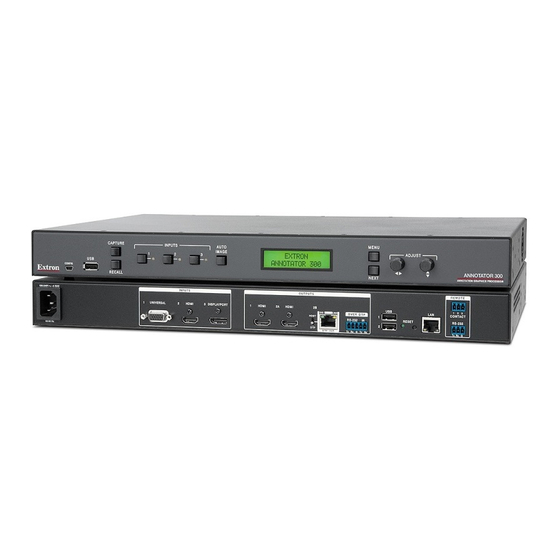
Rear Panel Features
100-240VAC
--A MAX
50/60 Hz
A
Power and video input connections
A
AC power connector
B
Universal analog 15-pin HD connector
C
HDMI connector (HDMI/DVI inputs)
D
DisplayPort connector
Installation
Mounting and Cabling
Step 1 — Mounting
a.
Turn off or disconnect all equipment power sources.
Mount the Annotator 300 to a rack using the pre-installed rack ears (see
b.
figure 1), or use an optional MBU 149 mounting kit (part number 70-222-01)
for under-the-desk mounting (see figure 2).
Step 2 — Connecting inputs
Connect analog video sources to the universal connector (see
a.
Compatible sources are RGB, YUV (HD or SD), RGBcvS, S-video and
composite video. Default setting for the input is auto-detect.
Connect a digital HDMI or DVI source to the HDMI connector (see
b.
Connect a DisplayPort input source to the DisplayPort connector (see
c.
above).
Step 3 — Connecting outputs
Connect suitable video displays to the two HDMI connectors (see
a.
Connect either an Extron DTP device to this connector for transmission over
b.
DTP (default), or connect an HDBaseT device if transmitting over HDBaseT
(see
above)
. Set the DIP switch to DTP or HDBaseT as applicable.
F
CAUTION:
Risk of damage to equipment.
DO NOT connect an HDBaseT unit if using DTP transmission.
The power carried over DTP may damage the unit.
Attention:
Cela risque d'endommager votre équipement.
Ne PAS connecter une unité HDBaseT si vous utilisez la transmission
DTP. L'alimentation transmise sur DTP peut endommager l'unité.
INPUTS
1
UNIVERSAL
2
HDMI
3
DISPLAYPORT
B
C
D
E
HDMI connectors (2) (HDMI/DVI outputs)
F
RJ-45 connector (DTP or HDBaseT
output), selectable by DIP switch
G
5-pole captive screw connector
(for DTP RS-232 and IR insert)
H
USB A connectors (2)
OUTPUTS
1
HDMI
2A
HDMI
2B
SIG
LINK
OVER DTP
HDBT
RS-232
HDBT
DTP
DTP OUT
Tx Rx G Tx Rx
E
F G
Outputs and control connections
I
J
K
screw connector
L
above).
B
above).
C
D
above).
E
Mounting Screws
(2) Places
Each Side
#8 Screw
(4) Places
Each Side
™
) commands.
www.extron.com.
REMOTE
USB
1
2 3
LAN
CONTACT
1
IR
RS-232
RESET
2
Tx Rx G
H I J K L
Reset button and LED
RJ-45 LAN connector
Remote RS-232 3-pole captive
Remote contact closure 3-pole
captive screw connector
Rack Ears
Rack Mount
Figure 1.
MBU 149
Mounting Bracket
Furniture Mount
Figure 2.
1
Advertisement

Related Manuals for Extron electronics Annotator 300


Summary of Contents for Extron electronics Annotator 300
- Page 1 This set up guide allows you to easily and quickly set up and configure your Annotator 300 using step by step instructions. It covers performing basic operations using the front panel controls and selected Simple Instruction Set (SIS ™...
-
Page 2: Front Panel Overview
Step 5 — Connecting user Connect user interface devices (mouse and keyboard) or touch panels to the Annotator 300 using either of the rear panel USB ports (see on page 1). Alternatively the front panel USB port can also be used to connect a user interface device. -
Page 3: Touch Panel Calibration
Annotation Graphics Overview The Annotator 300 output includes a graphical toolbar, which is used for annotation. The toolbar slides in from the right side, and can be accessed through a touch screen, or by using a compatible 2-button mouse attached to a USB port. - Page 4 Basic SIS Commands Table The Annotator 300 can be configured with specific SIS commands via USB, RS-232, or a LAN connection. This table lists a selection of the commands. For a full list of SIS commands see the Annotator 300 User Guide, online at www.extron.com.
Need help?
Do you have a question about the Annotator 300 and is the answer not in the manual?
Questions and answers