Table of Contents
Advertisement
Quick Links
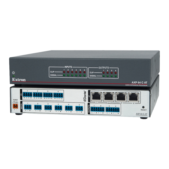
AXP 64 C AT • Setup Guide
Disconnecting Power and Mounting the AXP 64 C AT
Before beginning installation, disconnect power to the AXP 64 C AT and turn off all devices that will be connected to it. The
AXP 64 C AT is housed in a half rack wide, 9.5 inches deep, 1U high metal enclosure that can be set on a table (with the provided
rubber feet attached), or be mounted underneath a conference table, inside a credenza, or anywhere microphones or other
sources are located. Select a suitable mounting location, then choose an appropriate mounting option.
Make all external device connections before applying power.
Rear Panel Connections
1
IN G
01 02
IN G 01 02
POWER
12V
1.0A MAX
1
12 VDC power input connector
A
Digital I/O connectors
B
Mic/Line input connectors
C
Figure 1.
AXP 64 C AT Rear Panel
12 VDC power input – Connect the provided 12 VDC power supply to the rear panel captive screw connector (see
A
on page 2) and plug in the power cord. The front panel power LED blinks while the unit is booting, then lights steadily when
the AXP is powered and operational (see
Digital I/O connectors — Four 4-pole, 3.5 mm captive screw connectors associated with the
B
mic/line inputs provide digital input and output ports to connect microphones with logic circuits.
Each has an input (IN), a ground (G), and two output (O1 and O2) ports. The input port can enable
mic mute from a remote source. The two output ports can provide tally back to the mic LEDs to
indicate mic status. To wire these connectors, see the illustration at right.
Mic/Line 1-6 input connectors — Connect up to six balanced or unbalanced microphone or
C
mono line level devices using the 3-pole, 3.5 mm captive screw connectors. Wire as shown below.
Inputs 1 through 4 provide 48 volts phantom power.
Tip
Ring
Sleeve
Balanced Input
NOTE:
The first four inputs can access any Dante channel on the network. An input can be analog or digital. Each
channel can select either the associated rear panel analog input or the AT digital channel input assigned by Dante
Controller (see
2
3
4
IN G 01 02
IN G 01 02
2
3
4
5
figure
3,
Tip
Sleeve
Unbalanced Input
Dante Operation
on page 9).
This guide provides basic instructions for an experienced technician
to install the AXP 64 C AT Audio Expansion Processor. For additional
information and specifications, see the AXP 64 C AT product page at
www.extron.com.
1
6
1
2
Audio output connectors
D
AT port connectors
E
Reset button, recessed
F
, on page 3). Verify that the power LED lights.
A
Product Category
2
3
4
3
4
AXP 64 C AT
3 "
16
Do not tin the wires!
Digital I/O Wiring
RESET
figure 2
(5 mm) MAX.
I
G
O1
O2
1
Advertisement
Table of Contents

Related Manuals for Extron electronics AXP 64 C AT


Summary of Contents for Extron electronics AXP 64 C AT
-
Page 1: Rear Panel Connections
Product Category AXP 64 C AT • Setup Guide This guide provides basic instructions for an experienced technician to install the AXP 64 C AT Audio Expansion Processor. For additional information and specifications, see the AXP 64 C AT product page at www.extron.com. Disconnecting Power and Mounting the AXP 64 C AT Before beginning installation, disconnect power to the AXP 64 C AT and turn off all devices that will be connected to it. -
Page 2: Connecting Power
AXP 64 C AT • Setup Guide (Continued) Analog audio output connectors — Audio outputs 1 through 4 are on two 3.5 mm, 6-pole captive screw connectors. Connect up to four balanced or unbalanced mono line level or two stereo outputs to these 6-pole 3.5 mm captive screw X . -
Page 3: Front Panel Indicators
AXP 64 C AT to assist identification on the network. Both software applications are available at www.extron.com. On the Extron Electronics web page at www.extron.com, click the Download tab. The Download screen opens. On Download screen, click the Dante Controller link (... - Page 4 AXP 64 C AT • Setup Guide (Continued) On the Dante Controller web page, click Download ( On the Download Center page, follow the prompts to download the Dante Controller installer file. If the Download Center page has closed, click the Download tab again to access the left sidebar. On the left sidebar, click DSP Configurator Software.
- Page 5 Product Category Setting Up the Dante Network Communication between the AXP 64 C AT and a controlling device or a computer running software such as Extron DataViewer via a TCP socket using port 4333. Use a standard Ethernet cable to connect the AXP to a network via one of the four RJ-45 AT ports (see figure , on page 1).
- Page 6 AXP 64 C AT • Setup Guide (Continued) Click the Device Config tab ( ) to open the device configuration page. In the Rename Device panel, enter the new name of the device in the text field. No spaces are allowed in the name. Click Apply.
- Page 7 Product Category Configuring the AXP 64 C AT After the device is named, use the DSP Configurator to configure the AXP 64 C AT as desired. Ensure the control computer and AXP 64 C AT are connected to the same network and that the AXP 64 C AT is renamed for Renaming an AXP 64 C AT identification (see on page 5).
-
Page 8: Creating A Physical Dante Network
AXP 64 C AT • Setup Guide (Continued) Loading Building Blocks The discrete signal paths can be individually loaded with pre-configured, modular templates called building blocks. These blocks are designed for specific microphones, source devices, analog and digital inputs, and can streamline initial configuration. The building blocks contain configuration parameters tailored to a selected input device. -
Page 9: Daisy Chain Configuration
Product Category Daisy Chain Configuration A daisy chain configuration can also be used. Each unit is connected to both the previous unit and the next unit in the chain. DMP 128 AT AXP 64 C AT #1 AXP 64 C AT #3 AXP 64 C AT #2 100-240V ~ --A MAX DMP 128 C AT... - Page 10 Extron USA - West Extron USA - East +1.714.491.1640 +1.919.864.1000 +31.33.453.4040 +91.80.3055.3777 +1.714.491.1517 FAX +1.919.864.1001 FAX +31.33.453.4064 FAX +91.80.3055.3737 FAX www.extron.com © 2015 Extron Electronics All rights reserved. All trademarks mentioned are the property of their respective owners. 68-2721-50 A 03 15...
Need help?
Do you have a question about the AXP 64 C AT and is the answer not in the manual?
Questions and answers