Table of Contents
Advertisement
WWW.SEAGULLMODELS.COM
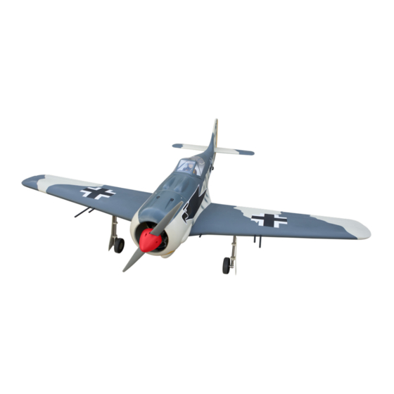
A S S E M B L Y M A N U A L
Code: SEA257
" Graphics and specifications may change without notice ".
Specifications:
Wingspan---------------80 in (203.3 cm).
Wing area---------------1083.8 sq.in ( 69.9 sq.dm).
Weight-------------------15.4 lbs ( 7.0 kg).
Length-------------------62.9 in ( 159.7 cm).
Engine-------------------33-38cc
Motor size---------------Power 160
Radio--------------------6 channels with 10 servos.
Electric Power Conversion Optional.
www.seagullmodels.com
1
Advertisement
Table of Contents

Related Manuals for Seagull Models FOCKE-WULF FW190


Summary of Contents for Seagull Models FOCKE-WULF FW190
- Page 1 WWW.SEAGULLMODELS.COM A S S E M B L Y M A N U A L Code: SEA257 “ Graphics and specifications may change without notice ”. Specifications: Wingspan---------------80 in (203.3 cm). Wing area---------------1083.8 sq.in ( 69.9 sq.dm). Weight-------------------15.4 lbs ( 7.0 kg). Length-------------------62.9 in ( 159.7 cm).
-
Page 2: Kit Contents
FOCKE-WULF FW190 is simply a joy. This instruction manual is designed to help you build a great flying aeroplane. Please read this manual throughly before starting assembly of your FOCKE-WULF FW190 . Use the parts listing below to indentify all parts. -
Page 3: Additional Items Required
WWW.SEAGULLMODELS.COM HINGING THE FLAP. KIT CONTENTS. SEA25701 Fuselage SEA25702 Wing set SEA25703 Tail set SEA25704 Canopy SEA25705 Cowling SEA25706 Aluminium tube SEA25707 Pilot ADDITIONAL ITEMS REQUIRED. 33cc-38cc gasoline engine. � Power 160 � Computer radio with 10 servos. � Glow plug to suit engine. �... -
Page 4: Wing Assembly
Focke- Wulf FW190 Instruction Manual. INSTALL FLAP CONTROL HORN. Install the flap control horn using the same method as same as the aileron con- trol horns. INSTALL THE AILERONS Fiberglass control horn CONTROL HORN. Fiberglass control horn Epoxy. Epoxy. WING ASSEMBLY. Please see below pictures. -
Page 5: Installing The Aileron Servos
WWW.SEAGULLMODELS.COM INSTALLING THE AILERON SERVOS. Epoxy. Servos Small weight Thread Because the size of servos differ, you may need to adjust the size of the precut opening in the mount. The notch in the sides of the mount allow the servo lead to pass through. - Page 6 Focke- Wulf FW190 Instruction Manual. C/A glue 4) Apply 2-3 drops of thin C/A to each 8) Remove the string from the wing at of the mounting holes. Allow the C/A to the servo location and use the tape to at- cure without using accelerator.
-
Page 7: Installation
WWW.SEAGULLMODELS.COM 9) Set the aileron hatch in place and use a AILERON PUSHROD HORN Phillips screw driver to install it with four INSTALLATION. wood screws. Please see below pictures. 2x10mm 50mm M3 lock nut. M3 clevis. INSTALLING THE FLAP SERVO. Repeat the procedure for the flap servo. - Page 8 Focke- Wulf FW190 Instruction Manual. INSTALLING THE FLAP PUSHROD. Cut. Repeat the procedure for the aileron pushrod. 50mm M3 lock nut. M3 clevis. STANDARD RETRACTABLE LANDING GEAR. Please see below pictures.
- Page 9 WWW.SEAGULLMODELS.COM Epoxy. Collar. 3x25mm Collar. Epoxy.
- Page 10 Focke- Wulf FW190 Instruction Manual. 3x10mm 50mm M3 clevis. M3 lock nut. Insert bomb onto the wing.
- Page 11 WWW.SEAGULLMODELS.COM Epoxy. Insert the wing gun onto the wing. Epoxy.
- Page 12 Focke- Wulf FW190 Instruction Manual. Epoxy. OPTIONAL ELECTRIC RETRACT LANDING GEAR 33cc. Electric retract landing gear is not in- cluded in this kit, however it is a very popular add-on as optional. If you want to use retracts in your FW190, we recom- mend that you buy a good set of electric retracts as the Himark AM07 Main Gear shown as below.
- Page 13 WWW.SEAGULLMODELS.COM 3x25mm...
-
Page 14: Installing The Fuselage Servos
Focke- Wulf FW190 Instruction Manual. INSTALLING THE FUSELAGE SERVOS. Because the size of servos differ, you may need to adjust the size of the precut opening in the mount. The notch in the sides of the mount allow the servo lead to pass through. - Page 15 WWW.SEAGULLMODELS.COM Loctite secure. Adjustable servo connector. Servo arm. Switch. Throttle servo arm. INSTALLING THE ENGINE SWITCH. Trim and cut. INSTALLING THE RECEIVER SWITCH. Install the switch into the precut hole in the side, in the fuselage. 3/32” Hole. Switch. INSTALLING THE STOPPER ASSEMBLY.
-
Page 16: Fuel Tank Installation
Focke- Wulf FW190 Instruction Manual. 6) When satisfied with the alignment of the stopper assembly tighten the 3 x 20mm ma- chine screw until the rubber stopper expands and seals the tank opening. Do not over- tighten the assembly as this could cause the tank to split. -
Page 17: Mounting The Engine
WWW.SEAGULLMODELS.COM 9) Drill a hole for the throttle pushrod. MOUNTING THE ENGINE . Please see below pictures. Vent tube. 5x80mm Fuel fill tube. Fuel pick up tube. 10) Connect the lines from the tank to the engine and muffler. The vent line will con- nect to the muffler and the line from the clunk to the carburetor. - Page 18 Focke- Wulf FW190 Instruction Manual. COWLING. Please see these below pictures. Reinstall the servo horn by sliding the connector over the pushrod wire. Center the throttle stick and trim and install the servo horn perpendicular to the servo center line. Cut.
-
Page 19: Installing The Spinner
WWW.SEAGULLMODELS.COM Because of the size of the cowl, it may be nec- essary to use a needle valve extension for the high speed needle valve. Make this out of suf- ficient length 1.5mm wire and install it into the end of the needle valve. Secure the wire in place by tightening the set screw in the side of the needle valve. -
Page 20: Hinging The Elevator
Focke- Wulf FW190 Instruction Manual. The propeller should not touch any part of the spinner cone. If it does, use a sharp modeling knife and carefully trim away the spinner cone where the propel- ler comes in contact with it. INSTALL ELEVATOR CONTROL HORN. - Page 21 WWW.SEAGULLMODELS.COM Use knife to remove covering INSTALLING RUDDER HINGE. Glue the rudder hinges in place using the same techniques used to hinge the el- evator. INSTALL RUDDER CONTROL HORN. Repeat steps to install the rudder control horn as same as steps done for ailerons. Fiberglass control horn Thin CA.
-
Page 22: Installing Horizontal Stabilizer
Focke- Wulf FW190 Instruction Manual. INSTALLING HORIZONTAL STABILIZER. ELEVATOR PUSHROD HORN INSTALLATION. Use Epoxy Glue to glue the Horizontal 1) Locate items necessary to install eleva- Stabilizer to the fuselage. tor pushrod. Elevator control horn. 2) Elevator pushrods assembly as pic- tures below. - Page 23 WWW.SEAGULLMODELS.COM M2 lock nut. M2 clevis. 915mm M2 lock nut. M2 clevis. Elevator pushrod. RUDDER PUSHROD HORN INSTALLATION. Rudder pushrod. 1) Locate items necessary to install rud- der pushrod. MOUNTING THE TAIL WHEEL. Rudder control horn. 2) Rudder pushrods assembly as pictures below.
- Page 24 Focke- Wulf FW190 Instruction Manual. Steering arm. Tail gear. M2 clevis. M2 lock nut.
- Page 25 WWW.SEAGULLMODELS.COM INSTALLATION PILOT AND CANOPY. 1) Locate items necessary to install pilot, seats. Epoxy. 2) A scale pilot is included with this ARF. The Seagull Pilot included fitting well to the cockpit. (or you can order others scale pilot figures made by Seagull factory. They are available at Seagull distributors.) If you are going to install a pilot figure, please use a sanding bar to sand the base...
-
Page 26: Apply The Decals
Focke- Wulf FW190 Instruction Manual. 4) Position the canopy onto the fuselage. APPLY THE DECALS. Trace around the canopy and onto the fu- selage using a felt-tipped pen. Carefully 1) If all the decals are precut and ready to cut and remove covering material from stick. - Page 27 WWW.SEAGULLMODELS.COM BALANCING. ATTACHMENT WING- FUSELAGE. 1) It is critical that your airplane be balanced correctly. Improper balance will cause your plane to lose control and crash. THE CENTER OF GRAV- ITY IS LOCATED 69MM BACK FROM THE LEADING EDGE OF THE WING AT THE WING ROOT.
-
Page 28: Control Throws
Focke- Wulf FW190 Instruction Manual. Lift the model. If the tail drops when CONTROL THROWS. you lift, the model is “tail heavy” and you must add weight* to the nose. If the nose Ailerons: drops, it is “nose heavy” and you must High Rate : 15mm add weight* to the tail to balance. -
Page 29: Flight Preparation
A) Plug in your radio system per the 2) Check every bolt and every glue manufacturer’s instructions and turn joint in the FOCKE-WULF FW190 everything on. to ensure that everything is tight and well bonded.
Need help?
Do you have a question about the FOCKE-WULF FW190 and is the answer not in the manual?
Questions and answers