Table of Contents
Advertisement
Quick Links
Advertisement
Chapters
Table of Contents

Subscribe to Our Youtube Channel
Summary of Contents for ADS-tec StoraXe PowerBooster GSS0608
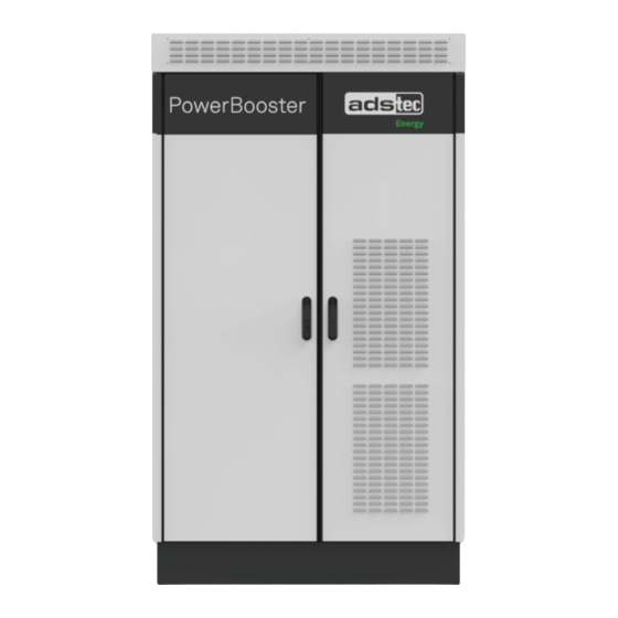
- Page 1 StoraXe PowerBooster Compact storage system GSS0608...
- Page 2 Copyright © ads-tec Energy GmbH. Copies and reproductions are only permitted with the permission of the author. Changes and errors excepted.
- Page 3 StoraXe PowerBooster GSS0608 Table of Contents Transport and advance information Instruction sheet in case of fire Declaration of conformity Instruction manual Electrical diagram Instructions smoke detector UN38.8 confirmation and MSDS...
- Page 5 Version Transport and preliminary information Preliminary information Transport and preliminary information StoraXe PowerBooster Compact Storage System GSS0608 Page 1 of 14 GSS0608 Version: 1.3...
- Page 6 Technical data ......................8 Temporary storage of the battery modules ..............9 Bottom view of unit .....................10 Checklist for commissioning ..................11 Contact .........................13 Support ADS-TEC Company address Appendix: Extract of the electrical diagram ..............14 Page 2 of 14 GSS0608 Version: 1.3...
- Page 7 Preliminary information 1 Transport information (Detail from the instruction manual) The battery modules are declared as dangerous goods when transported. Follow the relevant instructions on the packaging. The storage system is delivered in 3 parts: One pallet with storage system preassembled, without battery modules (approx. 800 kg •...
- Page 8 Preliminary information 2 Installation information german/english) (Detail from the information of the housing manufacturer – Blenden entfernen / Remove panels Lösen Sie die Befestigungsschrauben des vorderen Sockels. Unscrew the fastening screws of the front panel. Schieben Sie die Frontblende nach vorne und entfernen Sie diese.
- Page 9 Preliminary information Palette entfernen / Remove pallet Lösen Sie die 4 Befestigungsschrauben und entfernen Sie die Palette. Loosen the 4 fastening screws and remove the pallet. Page 5 of 14 GSS0608 Version: 1.3...
- Page 10 Preliminary information 3 Requirements regarding installation location (Detail from the instruction manual) The system is designed for stationary use in an outdoor area. Make certain that the specified environmental conditions are maintained at all times. Use in non-specified environments, e.g. on board ships, in explosive atmospheres or at high altitude (see the climatic environmental conditions) is prohibited.
- Page 11 Preliminary information Keep the existing housing doors closed. • • Observe the required minimum distances of 1.5 m to adjacent structures. Make additional spacing allowances for open doors and any escape routes. When installing in built-up areas, observe the local noise abatement regulations (Germany: "Technische Anleitung zum Schutz gegen Lärm"...
- Page 12 Preliminary information 4 Technical data GSS0608 AC coupled storage system with outdoor System type cabinet ADS-TEC Energy apps: peak-shaving, optimisation of personal Control / functions consumption, System ADS-TEC master interface Network connection Ethernet, RJ45, LTE Inverter Integrated Effective power 60 kW...
- Page 13 Preliminary information 5 Temporary storage of the battery modules Observe the manufacturer specifications and safety data sheets of the battery cell. • It is strongly advised that directive VDS-3103: 2019-06 also be observed. Store the battery modules in their original packaging in a dry, ideally air-conditioned indoor •...
- Page 14 Preliminary information 6 Bottom view of unit Page 10 of 14 GSS0608 Version: 1.3...
- Page 15 Preliminary information 7 Checklist for commissioning Page 11 of 14 GSS0608 Version: 1.3...
- Page 16 Preliminary information Page 12 of 14 GSS0608 Version: 1.3...
- Page 17 Preliminary information 8 Contact 8.1 Support ADS-TEC The ADS-TEC support team is available for inquiries from direct customers between 8:30am and 5:00pm, Monday to Friday. The support team can be reached via phone or e-mail: Phone: +49 7022 2522-203 Email: support.est@ads-tec-energy.com...
- Page 18 Preliminary information 9 Appendix: Extract of the electrical diagram Page 14 of 14 GSS0608 Version: 1.3...
- Page 19 Instruction sheet - Operating regulations and rules of conduct For handling lithium-ion batteries Place the filled form clearly visible near the system! Whoever operates a system is responsible for its proper operation Information about the system Designation and address of the system: Operating company of the system: Model (lithium-ion) and battery capacity (kWh): Conduct in case of fire...
- Page 20 Operating regulations and rules of conduct For handling lithium-ion batteries Place the filled form clearly visible near the system! Please provide this information sheet (or an information sheet according to local regulations) to the local fire protection officer / to the control center for the local fire protection concept.
- Page 23 Version Translation of the original instruction manual Translation of the original instruction manual StoraXe PowerBooster Compact Storage System GSS0608 Last changed: 05/2022...
- Page 24 A corresponding declaration of conformity is available for competent Conformity authorities at ADS-TEC and can be viewed upon request. © ads-tec Energy GmbH. Copying and duplication only with the Copyright permission of the originator. Page 2 of 72 GSS0608...
-
Page 25: Table Of Contents
Table of Contents Table of Contents Table of Contents ........................3 General information ......................6 About this document 1.1.1 Legal regulations and other information 1.1.2 Data, figures and modifications Applicable documents Limitation of liability Manufacturer and contact details Data, figures and modifications Trademarks Copyright Safety instructions ...................... - Page 26 Configuration of the SRC4310 via the web interface System start 8.2.1 System start for EMS operating mode 8.2.2 System start for Master operating mode Operation ........................56 Operating mode: ADS-TEC EMS 9.1.1 Operation 9.1.2 Optimisation of personal consumption 9.1.3 Peak-load capping 9.1.4...
- Page 27 Replacing the backup battery 11.3 Smoke detector 11.4 Cleaning 11.5 Information on storage Disposal ........................69 Service & support......................70 13.1 ADS-TEC support 13.2 Company address 13.3 Replacement parts Appendix ........................71 14.1 List of tables 14.2 List of figures 14.3...
-
Page 28: General Information
General information 1 General information 1.1 About this document This instruction manual is intended to ensure safe and efficient handling of the storage system. The instruction manual and all additional documents provided are part of the storage system and must be kept in the immediate vicinity of the system. -
Page 29: Applicable Documents
1.4 Manufacturer and contact details The manufacturer of the product is ads-tec Energy GmbH. The company is referred to in the following as ADS-TEC. -
Page 30: Data, Figures And Modifications
Any modified use or exploitation of the provided content, particularly duplication, modification or publishing in whatever form is permitted only with the prior consent of ADS-TEC. In the case of copyright infringement, ADS-TEC reserves the right to exercise all rights. Page 8 of 72 GSS0608 Version: 1.3... -
Page 31: Safety Instructions
Safety instructions 2 Safety instructions 2.1 Structure of safety instructions The safety and warning notices used in this documentation are based on the standards DIN ISO 3864-2 (signal words), ISO 3864-1 (safety colours), DIN EN 82079-1 and ANSI Z 535.4 (design). Signal word Meaning DANGER... -
Page 32: General Safety Instructions
Safety instructions 2.2 General safety instructions The system contains electrical voltages. Should comprehensive modifications be required, it is necessary to consult either with the manufacturer directly or with support personnel authorised by the manufacturer. If the system is opened up by an unauthorised person, the user may be subject to hazards as well as personal injury and the warranty will be invalidated. -
Page 33: Safety Symbols
Safety instructions 2.3 Safety symbols Symbol Meaning Designation of batteries in accordance with § 13 of the German Battery Act (BattG). Batteries may not be disposed of with household waste, but must rather be disposed of separately. Used batteries must be returned to the point of sale or a disposal system. -
Page 34: Special Rules Of Conduct In The Event Of Fire
Safety instructions 2.4 Special rules of conduct in the event of fire The system is equipped with a smoke detector that outputs an acoustic signal in the event of smoke emission and stops the power flow by opening the AC and DC isolating elements. NOTE Fire protection concept requirement. -
Page 35: Lithium-Ion Batteries
UN regulations for the given mode of transport. Responsibility for compliance with the legal regulations lies with the packer and shipper. If ads-tec Energy GmbH is involved with handling and packaging on an advisory level, then handling and packaging must only be performed in accordance with the instructions of ads-tec Energy GmbH. If packaging and part numbers of the packaging components are specified therein, only these are to be used. -
Page 36: Transportation Of Defective Or Damaged Lithium-Ion Batteries
Safety instructions 2.5.2 Transportation of defective or damaged lithium-ion batteries Defective or damaged batteries are subject to more stringent regulations, which include up to a complete ban on transport. The transport ban applies for air carriers (ICAO T.I., IATA DGR special provision A154). DANGER Risk of death due to poisoning! Outgassing substances can cause injury to eyes, skin and respiratory passages. -
Page 37: Storage And Supply Of Defective Or Damaged Lithium Batteries
Safety instructions 2.5.4 Storage and supply of defective or damaged lithium batteries Observe the manufacturer specifications and safety data sheets of the battery cell. It is strongly advised that directive VDS-3103: 2019-06 also be observed. Separate the defective lithium batteries (quantity restriction). •... -
Page 38: Product Description
Product description 3 Product description 3.1 General The battery storage system is a compact lithium-ion battery storage system for outdoor installation directly at the installation site. The system stores electrical power from the AC power supply network and feeds it back to the AC power supply network if necessary. -
Page 39: Technical Data
Product description 3.2 Technical data GSS0608 AC coupled storage system with outdoor System type cabinet ADS-TEC Energy apps: peak-shaving, optimisation of personal Control / functions consumption, System ADS-TEC master interface Network connection Ethernet, RJ45, LTE Inverter Integrated Effective power 60 kW... -
Page 40: Safety In The Total System
3.3 Safety in the total system Functionality: The safety system from ADS-TEC is based on a redundant safety concept which protects the battery cells from unsafe operating windows. The safety concept ensures that the battery is switched off reliably in the event of a fault, e.g. -
Page 41: Operating Instructions
In the case of improper use, ADS-TEC shall not accept responsibility or liability for injury or damage that is directly or indirectly attributable to the handling of the storage system. Should the battery storage cabinet have evident signs of damage caused by, for example, improper operation or storage conditions or due to improper use or handling, it must be shut down immediately. -
Page 42: Personnel Qualification
GSS and to recognise and avoid hazards independently: Professional training and experience. • • Specific product training by ADS-TEC. • Knowledge of relevant standards and regulations. 4.4.2 Transport personnel Transport personnel must meet the following qualifications and requirements in order to be able to carry out transport work at storage system and to independently recognise and avoid hazards: Trained in driving conveyor vehicles with driver's seat or driver's platform. -
Page 43: Target Group Matrix
Installation Commissioning Operation Maintenance Repair X (ADS-TEC) Decommissioning Table 3: Target group matrix 4.5 Personal protective equipment To prevent personal injury and damage to the plant, every activity requires the utmost concentration of the persons involved because these activities are always carried out close to earthed or live components. -
Page 44: Warranty / Repairs
Operating instructions 4.6 Warranty / repairs Repairs must be performed only by ADS-TEC or by persons authorised by ADS-TEC. Failure to observe this point will invalidate the warranty. The warranty will also be invalidated in the case of failure to observe... -
Page 45: Standards
Operating instructions Installation conditions: checklist "Commissioning Requirements" must completed signed • ( attachment: Transport and preliminary information). • The system is only suitable for outdoor installation. Observe the following floor space requirements for the system: • − The floor space is to be constructed at the installation location in accordance with the local conditions and technical data (... -
Page 46: Transport
Transport 5 Transport CAUTION Risk of irreversible damage to the components! Improper transport can irreversibly damage components. Use only means of transport that are designed for the weight of the storage system and battery modules. Transport the battery modules to the final location separately from the storage ... -
Page 47: Brief Description Of System Components
Brief description of system components 6 Brief description of system components 6.1 Double cabinet housing The outdoor double cabinet housing is designed to accommodate all system components. Depending on the components used, it has recesses for cable entry, ventilation openings on the base and roof as well as ventilation grilles on the right-hand door and on the right side of the cabinet. -
Page 48: Srs Storage Rack System
Brief description of system components 6.2 SRS Storage Rack System The storage system includes a battery storage system rack of type SRS0085. The SRS Storage Rack System comprises 8 battery modules and a SRC4 Storage Rack Controller for control and monitoring of the battery modules. Storage Rack Controller SRC1420 Storage Rack Controller... -
Page 49: Storage Rack Battery - Srb5106
Brief description of system components 6.2.1 Storage Rack Battery – SRB5106 The Storage Rack Battery (SRB) component represents one battery module of the storage system. The battery module contains the cells and its own battery management system (BMS). The SRB module displays its current status via a display on the front. -
Page 50: Storage Rack Controller - Src4310 (Src4)
Brief description of system components 6.2.2 Storage Rack Controller – SRC4310 (SRC4) The storage rack controller (SRC4310) component is the control unit of the StoraXe storage system and handles functions such as the following: Controls and monitors the connected battery modules via the battery management system (BMS) •... - Page 51 Brief description of system components 6.2.2.1 Connections on front side The Storage Rack Controller SRC4 is already configured and connected. Only the key of the key switch (2) still has to be inserted. 5: S IGURE TORAGE ONTROLLER FRONT VIEW EXAMPLE FIGURE Minus pole to SRB Key switch (ON –...
- Page 52 Brief description of system components 6.2.2.2 Status indicators SRC LED (top) Symbol Behaviour Description System is switched off Flashing SRC4 is starting up Flashing SRC4 is performing an update Static SRC4 in operating state Static SRC4 in warning state Static SRC4 in fault state Flashing Reset to factory settings...
-
Page 53: Storage Rack Controller Src1420 (Src1)
Brief description of system components 6.2.3 Storage Rack Controller SRC1420 (SRC1) The SRC1420 functions as a control unit for systems with inverters for the ads-tec EMS operating mode with apps (standard operating mode) as well as Master operating mode. Smart meters can be connected to the SRC1420. For this purpose, please refer to the list of supported smart meter models (... - Page 54 Brief description of system components 6.2.3.1 Connections on front side 6: SRC1420 S IGURE TORAGE ONTROLLER COMPONENT FRONT VIEW Position Labelling Description Lithium battery (1/2AA 3 V 850 mAh) (located under ventilation grille) START Power button T10A, H, Fine-wire fuse 5 mm x 20 mm / T10 250 V 250 VAC Reset Reset button...
- Page 55 Brief description of system components 6.2.3.2 Status indicators Status LED (front, top LED) Symbol Behaviour Description Status LED System is not connected to any voltage source (power supply/battery) Static System OK Static System in fault state Power LED (front, bottom LED) Symbol Behaviour Description...
-
Page 56: Inverter
Brief description of system components 6.3 Inverter 6.3.1 Scope of delivery 30 kVA bi-directional inverters with power section and control unit have been integrated for the storage system. The inverter transfers electrical power from the public grid to a battery and back. It is the interface between AC (public grid) and DC (battery system) and operates bidirectionally to charge and discharge the battery system. -
Page 57: Structure
Brief description of system components 6.3.3 Structure 7: I – IGURE NVERTER COMPONENT POSITION EXAMPLE FIGURE Inverter 1 master, top Inverter 2 slave, bottom 8: V IGURE IEW OF INVERTER EXAMPLE FIGURE Version:1.3 GSS0608 Page 35 of 72... -
Page 58: Air-Conditioning System
Brief description of system components 6.4 Air-conditioning system The air-conditioning system is a switching cabinet-type cooling unit of the Blue e+ series from Rittal. The air-conditioning system is preconfigured for cooling the battery modules and is equipped with an additional heater for lower temperatures. -
Page 59: Installation
Installation 7 Installation 7.1 Checking delivery package Check that the delivery package is complete and in flawless condition. If parts are missing or damaged: Do not use the product! Submit a complaint to the supplier. • The delivery package consists of: GSS0608 storage system (preassembled and prewired). -
Page 60: Assembly At Final Location
Installation NOTE Note position of cable gland. When preparing the floor space, pay attention to the recess for cable gland from below. 7.3 Assembly at final location The storage system is delivered preassembled. The individual components are pre-installed and already connected. -
Page 61: Electrical Connection
Installation 7.4 Electrical connection DANGER Risk of death due to high voltages! High voltages can cause fatal injury. Before starting work, make sure that the main switch is set to "OFF" and the storage system is in a de-energised state and protected from being switched on again. -
Page 62: Earth Connection
Installation 7.4.2 Earth connection NOTE Observe the earth connection. The housing system must be properly earthed at the designated location with an earthing cable and maintained in accordance with VDE0113 (Electrical diagram in manual GSS0608). The device includes interference suppressor filters with increased earth leakage ... - Page 63 Installation 12: P IGURE OSITION OF EQUIPOTENTIAL BONDING RAIL Equipotential bonding rail with EXAMPLE FIGURE cover Remove the cover of the • equipotential bonding rail. • Connect the foundation earth electrode to the equipotential bonding rail. Keep the earth connection as short as possible.
-
Page 64: Ac Power Connection
Installation 7.4.3 AC power connection The AC power cable is fed in via the cable inlet on the underside of the housing. Observe the cable cross section 5-wire cable electrical diagram (Electrical diagram in manual GSS0608). Follow the electrical diagram for all electrical connections. - Page 65 Installation 15: P IGURE OSITION OF CONNECTION EXAMPLE FIGURE Connect the wires of the AC • supply line from below as follows: (phase 1) (phase 2) (phase 3) (neutral conductor) (protective earth) NOTE: Observe the clockwise rotating field. If the L1, L2 and L3 sequence is incorrect, the inverters will not work! 16: C...
-
Page 66: Communication Port
Installation 7.4.4 Communication port The cable entries on the underside of the housing are used to feed in the communication line for local diagnosis and monitoring of the battery storage system, the optional supply line for connecting charging stations, smart meters or service, and the optional supply line for an external emergency stop signal. Follow the electrical diagram for all electrical connections. -
Page 67: Installing The Battery Modules
Installation 7.5 Installing the battery modules NOTE Observe qualifications. Only qualified electricians are allowed to install the battery modules! The procedure described in the following for assembling the storage system is to be observed under all circumstances. The module label can be found imprinted on the front label of the module. 7.5.1 Inserting the battery modules Owing to the heavy weight of the SRB modules, it is essential to follow the procedure described below for installing the components. - Page 68 Installation Basic procedure for inserting battery modules: Place the battery module on the • support rails of the lifting equipment and position at the intended installation height. Note the order of installation when doing so. • Push the module halfway into the rack.
-
Page 69: Installing The Power Cabling
Installation 7.5.2 Installing the power cabling The procedure described in the following for assembling the power cabling is to be observed under all circumstances. The module label can be found imprinted on the front label of the module. The modules are equipped ex factory with a transport cover on the plus pole. This transport cover is screwed to the module with Torx-TR 20 safety screws. - Page 70 Installation Negative power cable (- -) Connect the negative power • cable from the SRC4310 controller to the first SRB battery module with the short cable (- -). 23: A IGURE TTACHING THE POWER CABLE Transport cover 1 • Remove the transport cover on the first battery module.
- Page 71 Installation Transport cover 2 Remove the transport cover on • the second battery module. 26: A IGURE TTACHING THE POWER CABLE Power cable 2 (+ -) • Insert the positive plug and screw the cable onto the minus pole of the second battery module.
- Page 72 Installation Long positive power cable (+ +): Plus pole of SRC4310 controller Plus pole of bottom battery module Connect the plus pole of the • bottom module to the plus pole of the SRC4310 controller with the long cable (+ +). 28: A IGURE TTACHING THE POWER CABLE...
-
Page 73: Installing The Communication Cabling
Installation 7.5.3 Installing the communication cabling The procedure described in the following for assembling the storage system is to be observed under all circumstances. The designation on the SRB modules is CAN-BUS1 for the input and CAN-BUS2 for the output to the next module. The module label can be found imprinted on the front label of the module. Communication cable 1 (short) Connect the communication •... - Page 74 Installation Order of all communication cables Repeat the previous step for the • remaining modules. Note that the order is from top to bottom. Attach cable routing guide rails Fasten the cable guide rails • 31: A IGURE TTACHING THE COMMUNICATION CABLE Terminator plug Attach the terminator plug •...
-
Page 75: Commissioning
Commissioning 8 Commissioning NOTE Observe qualifications. Commissioning must be performed only by qualified electricians! It is essential to follow the procedure described below! 8.1 Configuring the components 8.1.1 Network overview IP addresses Subnet Gateway Operating mode SRC1420 DHCP 172.17.10.100 255.255.255.0 DHCP... -
Page 76: Configuration Of The Src1420 Via The Web Interface
8.1.2 Configuration of the SRC1420 via the web interface The web interface of the SRC1420 delivers state values for the entire system. Determine the SRC1420 system from the list of ads-tec devices and enter this IP address in the browser. The web interface is displayed. -
Page 77: System Start
6. Set the desired application types and parameters via the apps. Please note the documentation for the StoraXe Machine Interface ( ADS-TEC EMS_StoraXe Machine Interface). 7. ADS-TEC EMS takes over the control of the system. 8.2.2 System start for Master operating mode 1. Switch on the main switch. -
Page 78: Operation
TEC EMS_StoraXe Machine Interface". The control is automated via the local ADS-TEC EMS energy management system for easy operation and control of the storage system. Various standard apps are available for the respective applications described in greater detail below. -
Page 79: Selfcare
For details on the Master communication interface, please see the description "ADS-TEC Master". If the ADS-TEC storage system as a complete unit with inverter is controlled by means of an external energy management system provided by the customer, then the storage system is controlled via the ADS- TEC master protocol, which uses Modbus/TCP. -
Page 80: Switching Off The System
Switching off the system 10 Switching off the system 10.1 Switching off the system before performing maintenance or decommissioning NOTE Observe qualifications. Maintenance work, service and repairs as well as decommissioning must be performed by qualified electricians only. Switch off all fuses belonging to the system. Use a suitable testing device to check that no •... -
Page 81: Order Of Disassembly
Switching off the system 10.2 Order of disassembly The procedure described in the following for disassembling the storage system is to be observed under all circumstances. The modules are removed from the cabinet starting with the top module and working down. - Page 82 Switching off the system − Attach the protective covers. 34: A IGURE TTACHING THE TRANSPORT COVER − Undo the screws securing the communication cables (2 screws per connector, shown in blue in the drawing). − Disconnect all communication cables in the cabinet. 35: D IGURE ISCONNECTING THE COMMUNICATION...
- Page 83 Switching off the system − Detach the front cable guide rails (shown in blue in the drawing). 37: D IGURE ETACHING THE CABLE GUIDE RAILS − Remove the socket head cap screws securing modules (M6x16 DIN 912, 4 screws per module, shown in blue in the drawing).
- Page 84 Switching off the system − Unscrew the socket head cap screws (M5x16 DIN 912, 2 screws per module, shown in blue in the drawing). These screws are used as a removal aid. Remove the top modules first. 39: R IGURE EMOVING THE REMOVAL AID SCREWS INFO: The socket head of the removal aid...
- Page 85 Switching off the system Use lifting equipment to remove the battery modules. − Pull out the top battery module. The module can be pulled halfway out of the cabinet without tipping. − Lift the other modules out from top to bottom. 41: L IGURE IFTING OUT THE BATTERY MODULE...
-
Page 86: Maintenance & Storage
NOTE Contact ADS-TEC service If SRB modules need to be replaced, please contact ADS-TEC support. Replacement and exchange may only be carried out by qualified and specially trained electricians. NOTE... - Page 87 Maintenance & storage • For further information, see chap. 11.3 Follow maintenance Inverter • instructions manufacturer’s documentation! Clean ABB PQstorl • Every 12 months (1 and 2) • Check AC/DC torques Every 12 months Check fans (replace • Every 5 years necessary) Follow maintenance...
-
Page 88: Replacing The Backup Battery
Maintenance & storage 11.2 SRS battery system NOTE Observe procedure. The maintenance intervals/cleaning of the storage system may only be carried out after the system is shut down. NOTE Observe the aids. Compressed air and dry cleaning cloths must be used for any cleaning work ... - Page 89 Maintenance & storage • Replace the battery (CR2032), paying attention to the polarity. 43: R SRC4310 IGURE EPLACING THE BACKUP BATTERY • Reinsert the slot. When correctly installed, the arrows on the slot and the front point towards one another. 44: R SRC4310 IGURE...
-
Page 90: Smoke Detector
Maintenance & storage 11.3 Smoke detector Description Maintenance interval Visual inspection and care: 1 x annually Perform a visual inspection of the smoke detector for humidity, dust, traces of heat or other abnormalities. The device should be wiped dry if necessary and vacuumed from the outside with a vacuum cleaner. -
Page 91: Disposal
(cf. chap. 2.6 Lithium-ion batteries). If ADS-TEC is involved with handling and packaging on an advisory level, then handling and packaging must only be performed in accordance with the instructions of ADS-TEC. If packaging and part numbers of the packaging components are specified therein, only these are to be used. -
Page 92: Service & Support
Service & support 13 Service & support ADS-TEC and its partner companies provide you with comprehensive maintenance and support services, ensuring quick and competent assistance should you have any questions or queries with regard to ADS- TEC products and equipment. -
Page 93: Appendix
Appendix 14 Appendix 14.1 List of tables Table 1 Signal colours ............................. 9 Table 2: Safety symbols ............................11 Table 3: Target group matrix ..........................21 Table 4: Personal protective equipment .........................21 14.2 List of figures ......................16 1: V IGURE IEW OF BATTERY STORAGE SYSTEM ........................25 2: D IGURE... -
Page 94: Revision History
Appendix 35: D ...................60 IGURE ISCONNECTING THE COMMUNICATION CABLES .......................60 36: U IGURE NSCREWING THE CABLE GUIDE RAILS ......................61 37: D IGURE ETACHING THE CABLE GUIDE RAILS 38: R ) ..............61 IGURE EMOVING THE BATTERY MODULE SCREWS EXAMPLE FIGURE 39: R .......................62 IGURE EMOVING THE REMOVAL AID SCREWS... - Page 95 Energy GmbH Phone. +49 7022 2522-203 Heinrich-Hertz-Straße 1 72622 Nürtingen +49 7022 2522-406 Germany E-mail support@ads-tec.de Customer Control DVG-SRC1420 Street ZIP code / City Phone E-mail Project name Storage Container GSS0608_EN Place of installation Manufacturer (company) ads-tec Energy GmbH...
-
Page 96: Table Of Contents
Parts list : PXC.1201662 - PXC.0201346 30.11.2021 Vetter.Benjamin /1.b Parts list : PXC.3209662 - PXC.1900895 30.11.2021 =01+S2/1 Date 18.02.2022 ads-tec Energy GmbH Table of contents : =00+A/1 - /1.b PJ-EST-000085 Vetter.Benjamin Grid Support Station 0608 Appr Page Modification Date Name... - Page 97 Busbar 3x 12 x 5 400V AC 50 Hz 400V AC 50 Hz -L1:1 -L1:2 -L1:3 Grid0 L1 / 2.0 -L2:1 -L2:2 -L2:3 Grid0 L2 / 2.0 -L3:1 -L3:2 -L3:3 Grid0 L3 / 2.0 Short-circuit proof 1/L1 3/L2 5/L3 1/L1 3/L2 5/L3 -K10...
- Page 98 Busbar 3x 12 x 5 400V AC 50 Hz -L1:4 -L1:5 Grid0 L1 -L2:4 -L2:5 Grid0 L2 -L3:4 -L3:5 Grid0 L3 Grid0 N -F10 -F11 C16A C10A 2,5² 2,5² 2,5² 2,5² 2,5² -KEC1 =02+S/6.2 X10L -X11L Air-conditioning system SRC 1 + Switch cabinet heating 24V DC -Power supply unit ABB protective cover...
- Page 99 Grid5 L2 Grid5 N Grid5 PE -G10 TRIO-PS-2G/1AC/24DC/10 / 8.5 / 7.1 2,5² 2,5² -X1.1L -X1.1L M14. / =03/2.0 M13. / =03/1.0 M12. / =10+S1/2.7 M11. / =02+S/6.1 / 4.1 / 7.1 / =02+S/6.1 -X1.1L 6,3A -X1.1L P14. / =03/2.0 P13.
- Page 100 =04+S1/5.4 K100_A1 =04+S1/5.5 K10_21 -WK10 /4.7 2X0,75 -X1.2 -X1.2L -K10 /4.1 -K11 /4.2 -X1.2L -X1.2 -WK100 -K100 ÖLFLEX® CLASSIC 110 /4.5 -WK10 2X0,5 /4.7 300/500V 2X0,75 -X1.2 -X1.2L -K10 -K11 -K100 Feedback-K AC3:37KW/400V, AC/DC 20-33V AC3:37KW/400V, AC/DC 20-33V =04+S1/5.2 -X1.2L -X1.2 M11.1 K100_A2...
- Page 101 -A10 Modbus Converter PQConnect IP 172.17.10.200 RJ45 RJ12 LANEC1.1 / =05+S1/1.2 -WABB_1_LAN -WABB_1_CAN -EC1.1 Power supply USB Host SK.3124300 IP : 172.17.10.20 3124300 micro USB Modbus Modbus ABB Inverter1 ABB_CAN Klima1 =02+S/6.1 =03/1.0 PQstorI =05+S1/1.3 IoT Interface Date 30.11.2021 Climate monitoring Vetter.Benjamin IoT Interface Grid Support Station 0608...
- Page 102 LAN interface SRC1 LAN interface SRC1 - Rear - Rear =05+S1/1.4 =05+S1/1.3 CUSTOMER_LAN SERVICE_LAN M11.1 IL_1 IL_2 / 4.1 =03/1.1 / =03/1.1 -WLANC -WLANS FC10_ PE / 1.3 -FC10 -FC10 -F03 -F04 /8.7 /8.5 RJ45 RJ45 RJ45 RJ45 PE (via DIN rail) PE (via DIN rail) LAN interface LAN interface Support...
- Page 103 Date 25.11.2021 CAD Low voltage distributor Besitzer View Mounting panel Grid Support Station 0608 mounting plate Appr Page Enclosure right Modification Date Name Original Replacement of Replaced by Page...
- Page 104 =02+S/4 Date 25.11.2021 CAD Low voltage distributor Besitzer View Mounting panel Grid Support Station 0608 mounting plate Appr Page Enclosure right Modification Date Name Original Replacement of Replaced by Page...
- Page 105 S11_14 =04+S1/5.6 -U101 S11_13 =04+S1/5.2 -WS11 ÖLFLEX® CLASSIC 110 2X0,5 300/500V -S11 Door switch right =05+S1/1.8 =01+S2/13 Date 13.09.2021 Door switch right Vetter.Benjamin LTE antenna Grid Support Station 0608 Enclosure Appr Page Enclosure completely Modification Date Name Original Replacement of Replaced by Page...
- Page 106 =01+S2/7.1 Klima1 -X10.1 =01+S2/2.2 Grid1 L1 -X1.2L Grid1 L2 Grid3 L2 Grid4 PE =01+S2/2.2 =01+S2/2.5 =04+S1/6.5 Grid4 N =04+S1/6.5 Grid1 L3 Grid3 N Grid4 L2 =01+S2/2.2 =01+S2/2.6 =04+S1/6.5 Grid1 PE =01+S2/2.2 -WEC1 -WEC2 ÖLFLEX CLASSIC 110 G ÖLFLEX 191 G 4x2.5 3x1.5 -WM1...
- Page 107 M13. =01/3.5 =01/3.5 P13. DZ-SONS-20192-0/A -W10.1 -WABB_2_CAN -U10 =01/8.8 IL_2 IL_1 =01/8.7 DZ-SONS-20192-0/A -W10.1 DIP Switch Position -XCAN -XCAN -WABB_1_CAN =01/7.6 ABB_CAN -XDC -XAC DZ-SONS-20196-0/A -WU100 -WPEU100 gn/ge -U1000 -U100 Snap ferrite -U1001 ABB Inverter2 Snap ferrite PQstorI HLV 710-500/55 DZ-SONS-20194-0/A -WDCU100 PLUS1...
- Page 108 M14. =01/3.5 P14. =01/3.5 DZ-SONS-20192-0/A -W20.1 -U20 DIP Switch Position -XCAN -XCAN 1 2 3 4 5 6 7 ABB Inverter2 PQstorI -XDC -XAC DZ-SONS-20196-0/A -WU200 -WPEU200 gn/ge -U2000 Snap ferrite -U2001 -U200 Snap ferrite DZ-SONS-20194-0/A -WDCU200 HLV 710-500/55 PLUS2 MINUS2 =04+S1/6.7 =04+S1/6.8...
- Page 109 =05/1.8 XA_1 =05/1.8 XA_ENABLE_1 =05/1.8 XA_3 XA_4 =05/1.8 XA_5 =05/1.8 XA_6 =05/1.8 XB_6 =05/1.8 XB_Feedback-K =05/1.8 XB_Smoke =05/1.8 XB_3 =05/1.8 XB_DOOR_RIGHT =05/1.8 =05/1.8 XB_1 DZ-SONS-20191-0/A -X12.2 -XL12.2 24V+ 24V+ -XL12.1 =03+S2/2 Date 30.11.2021 Signal exchange Besitzer Grid Support Station 0608 Support rail Appr Page...
- Page 110 Grid4 PE / =02+S/6.7 Grid4 N / =02+S/6.7 =03+S2/1.5 =03+S2/1.5 Grid4 L2 / =02+S/6.7 PLUS1 MINUS1 =03+S2/2.5 =03+S2/2.5 PLUS2 MINUS2 16² 16² 16² 16² -X14L -XL10 Grid2 PE / =05/1.8 PLUS MINUS DZ-SONS-20189-0/A Grid2 N / =05/1.8 =10/1.7 =10/1.6 -X11.0 -W10 -X14.0 Grid2 L2...
- Page 111 ENABLE_B =10/2.2 Smoke -U10 Switching relay ER10018930 ESYLUX ER10018923 smoke detector DZ-SONS-20219-0/A -WU10 ÖLFLEX CLASSIC 110 3x0,75 -X12.1 =05/1 Date 13.09.2021 smoke detector Vetter.Benjamin Grid Support Station 0608 Support rail Appr Page Enclosure left Modification Date Name Original Replacement of Replaced by Page...
- Page 112 =02+S/4.6 =01+S2/8.3 SERVICE_LAN -SRC1 12VDC IP : 172.17.10.100 XA_1 / =04/5.1 =01+S2/7.5 =01+S2/8.2 XA_ENABLE_1 / =04/5.1 ABB Inverter1 CUSTOMER_LAN IP : 172.17.10.100 XA_3 / =04/5.1 PQstorI XA_4 / =04/5.1 XA_5 / =04/5.1 XA_6 / =04/5.1 3 4 5 6 3 4 5 6 XB_6 / =04/5.1 XB_Feedback-K...
- Page 113 NSGAFÖU 1.8/3 kV 1x50 1800/3000V -WCAN1 CAN Bus -SRC4310 /2.2 -X300 -X1600 D-SUB9 Current -WCAN2 Sensor CAN Bus NSGAFÖU 1.8/3 kV LF 310-S 1x50 1800/3000V -X300 NSGAFÖU 1.8/3 kV 1x50 Front 1800/3000V BATT CAN-BUS1 RESET CR2032 76-99V DC -CAN1 -CAN2 -SRB1 SRB5083 -X203...
- Page 114 =02+S/6.8 GND1 =01+S2/3.5 P12. Tach M12. =02+S/6.8 =01+S2/3.5 =02+S/6.8 -WX1300 Klima Klima (Air in) (Air out) DZ-SONS-20187-0/A -WX203 2x0,75 =05/1.3 SRC1-2 =04/5.5 ENABLE_A =04/7.1 ENABLE_B -LAN CAN: -X1301 -X1300 -X1200 Data Out: -SRC4310 -X1701 -X1700 -X1400 RJ45 -X1500 Mini-DIN4 Mini-DIN4 D-SUB9 /1.3 CAN_L 3...
- Page 115 =01+S2-X1.2L Feed-through terminal block PT 2,5-QUATTRO/2P PXC.3209662 =01+S2-X1L Feed-through terminal block PT 16 N PXC.3212138 =10+S1/2 Date 30.11.2021 ads-tec Energy GmbH Parts list : ABB.2GCA298532A0070 - Vetter.Benjamin PXC.3212138 Grid Support Station 0608 Appr Page Modification Date Name Original Replacement of...
- Page 116 PXC.3209688 =04+S1-XL10 Feed-through terminal block UKH 50 PXC.3009118 =04+S1-XL10 Fixed bridge FBI 2-20 PXC.0201346 Date 30.11.2021 ads-tec Energy GmbH Parts list : PXC.1201662 - PXC.0201346 Vetter.Benjamin Grid Support Station 0608 Appr Page Modification Date Name Original Replacement of Replaced by...
- Page 117 =10+S1-X1300 Printed-circuit board connector MC 1,5/ 9-ST1F-5,08 PXC.1900950 =10+S1-X1301 Printed-circuit board connector MC 1,5/ 3-ST1F-5,08 PXC.1900895 Date 30.11.2021 ads-tec Energy GmbH Parts list : PXC.3209662 - PXC.1900895 Vetter.Benjamin Grid Support Station 0608 Appr Page Modification Date Name Original Replacement of...
- Page 119 DATA SHEET PROTECTOR K RELAY Item number GTIN Product description ER10018923 4015120018923 • Switching relay for triggering external devices such as sirens, flash lights and alarm horns • Can be used with PROTECTOR K 9 V, PROTECTOR K 9 V Lithium, PROTECTOR GD 230 V and PROTECTOR K 230 V •...
- Page 130 SAMSUNG SDI Co., LTD Revision date: Sep. 21. 2016 Revision no.:2.0 MODEL CM0940R0008A (94Ah capacity) 1. Product and Company Identification USA, EU Important Note: As a solid, manufactured article, exposure to hazardous ingredients is not expected with normal use. This battery is an article pursuant to 29 CFR 1910.1200 and, as such, is not subject to the OSHA Hazard Communication Standard requirement.
- Page 131 SAMSUNG SDI Co., LTD Revision date: Sep. 21. 2016 Revision no.:2.0 MODEL CM0940R0008A (94Ah capacity) Remark: The information and recommendations set forth are made in good faith and believed to be accurate as of the date of preparation. SAMSUNG SDI Co., Ltd. makes no warranty, expressed or implied, with respect to this information and disclaims all liabilities from reliance on it.
- Page 132 SAMSUNG SDI Co., LTD Revision date: Sep. 21. 2016 Revision no.:2.0 MODEL CM0940R0008A (94Ah capacity) Further Information For information purposes: (*) Main ingredients: Lithium hexafluorophosphate, organic carbonates Because of the cell structure the dangerous ingredients will not be available if used properly. During charge process a lithium graphite intercalation phase is formed.
- Page 133 SAMSUNG SDI Co., LTD Revision date: Sep. 21. 2016 Revision no.:2.0 MODEL CM0940R0008A (94Ah capacity) Personal precautions Use personal protective clothing. Avoid contact with skin, eyes and clothing. Avoid breathing fume and gas. Environmental precautions Do not discharge into the drains/surface waters/groundwater. Methods for cleaning up/taking up Take up mechanically and send for disposal.
- Page 134 SAMSUNG SDI Co., LTD Revision date: Sep. 21. 2016 Revision no.:2.0 MODEL CM0940R0008A (94Ah capacity) Hand protection No specific precautions necessary. Eye protection No specific precautions necessary. Skin protection No specific precautions necessary. 9. Physical and Chemical Properties USA, EU Appearance Form: Solid...
- Page 135 SAMSUNG SDI Co., LTD Revision date: Sep. 21. 2016 Revision no.:2.0 MODEL CM0940R0008A (94Ah capacity) 11. Toxicological Information USA, EU Empirical data on effects on humans If appropriately handled and if in accordance with the general hygienic rules, no damages to health have become known.
- Page 136 SAMSUNG SDI Co., LTD Revision date: Sep. 21. 2016 Revision no.:2.0 MODEL CM0940R0008A (94Ah capacity) Marine transport UN number: 3480 IMDG code: Marine pollutant: Hazard label: IMDG packing group: EmS: F-A, S-I Limited quantity: None Description of the goods Lithium-ion batteries Air transport UN/ID number: 3480...
- Page 137 SAMSUNG SDI Co., LTD Revision date: Sep. 21. 2016 Revision no.:2.0 MODEL CM0940R0008A (94Ah capacity) Labeling Hazardous components which must be listed on the label As an article the product does not need to be labeled in accordance with EC directives or respective national laws. EU regulatory information 1999/13/EC (VOC): 16.
- Page 140 Energy GmbH Heinrich-Hertz-Str. 1 72622 Nuertingen Germany Phone +49 7022 2522-201 Email: energy-storage@ads-tec-energy.com Home: www.adstec-energy.com...
Need help?
Do you have a question about the StoraXe PowerBooster GSS0608 and is the answer not in the manual?
Questions and answers