Table of Contents
Advertisement
Quick Links
Advertisement
Table of Contents

Related Manuals for Keysight M9005A


Summary of Contents for Keysight M9005A
- Page 1 User Guide Keysight M9005A PXIe Chassis...
- Page 3 Software. The EULA and MATION CONTAINED HEREIN. SHOULD 900 S. Taft Ave. the license set forth therein, does not KEYSIGHT AND THE USER HAVE A SEP- Loveland, CO 80537 USA require or permit, among other things, ARATE WRITTEN AGREEMENT WITH...
- Page 4 Cleaning Do Not Remove Instrument Cover The following general safety precau- tions must be observed during all Clean the outside of the Keysight mod- Only qualified, service-trained person- phases of operation of this instrument. ule/chassis with a soft, lint-free, nel who are aware of the hazards Failure to comply with these precau- slightly dampened cloth.
- Page 5 To return unwanted products, contact leak or deteriorate during normal use. from AC mains when your local Keysight office for more Forty years is the expected useful life switch is in standby. information. of this product.
-
Page 7: Table Of Contents
Rack Mount Kit..........6 M9005A Chassis Backplane Overview....... . . 7 Interoperability with CompactPCI. - Page 8 M9005A Specifications ........
- Page 9 Hybrid Slot Pinouts..........51 Index Keysight M9005A PXIe Chassis User Guide...
- Page 10 Keysight M9005A PXIe Chassis User Guide...
-
Page 11: Getting Started
M9005A PXIe Chassis User Guide Getting Started This chapter describes the key features of the M9005A chassis, and lists the kit contents and optional equipment you can order from Keysight. -
Page 12: Unpacking
Retain the packing material for possible inspection and/or reshipment. What You Need to Get Started The M9005A chassis kit contains the following items: - M9005A PXIe Chassis User Guide - Four filler panels. Additional filler panels (part number Y1213A) are available. -
Page 13: Key Features
Unpacking Getting Started Key Features The M9005A chassis combines a 5-slot PXI backplane with a structural design that has been optimized for maximum usability in a wide range of applications. The key features of the chassis include the following: - Accepts 3U PXI Express, CompactPCI Express, and hybrid slot compatible PXI-1/CompactPCI (PICMG EXP.0 R1.0) modules... -
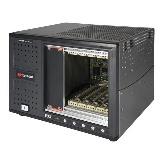
Page 14: Chassis Description
Getting Started Unpacking Chassis Description Figure 1 Figure 2 show the key features of the M9005A chassis front and rear panels. Figure 1 shows the front view of the M9005A. Figure 2 shows the rear view of the M9005A. Figure 3 shows the bottom of the chassis. - Page 15 6 Auto/High Fan Speed Selector Switch 3 Power Supply Fan Exhaust 7 Rubber Foot 4 Chassis Controller Connector Figure 2 Rear View of the M9005A Chassis 1 Rubber Foot 3 Fan Intake Cover 2 Power Switch 4 Fan Intake Cover Screw...
-
Page 16: Additional Equipment
Slot blocker kits (part number Y1212A) are available from Keysight for improved thermal performance when all slots are not used. Rack Mount Kit A rack mount kit (part number Y1274A) is available for mounting the M9005A chassis into a 19 in. instrument cabinet. Refer to Figure 19 on page 48 for more information. -
Page 17: M9005A Chassis Backplane Overview
Getting Started M9005A Chassis Backplane Overview Interoperability with CompactPCI The design of the M9005A chassis provides you the flexibility to use the following devices in a single PXI Express chassis: - PXI Express compatible products - CompactPCI Express compatible Type-2 peripheral products... -
Page 18: Interface
Getting Started M9005A Chassis Backplane Overview Interface The M9005A chassis has a built-in x1 interface that can be accessed through the chassis controller connector on the back of the chassis, as shown in Figure The interface can be cabled to a remote system with a host card using a x1 cable to provide control of the M9005A chassis. -
Page 19: Pxi Local Bus
The PXI trigger lines allow you to send trigger signals to, and receive trigger signals from, every slot in the chassis. Static trigger routing (user-specified line assignments) can be configured through Keysight Connection Expert. Dynamic routing of triggers (automatic line assignments) is supported through certain Keysight drivers. -
Page 20: System Reference Clock
M9005A Chassis Backplane Overview System Reference Clock The M9005A provides a 10 MHz clock (PXI_CLK10) and 100 MHz clock (PXIe_CLK100) to each peripheral slot. The 100 MHz clock is a high speed LVPECL clock, while the 10 MHz clock is a TTL/CMOS clock. The backplane also provides a PXIe_SYNC100 signal which asserts a 10 ns pulse which is synchronous to PXIe_CLK100. - Page 21 0 1 2 3 4 5 6 7 8 9 0 1 2 3 4 5 6 7 8 9 0 1 2 3 4 5 6 7 8 9 PXIe_CLK100 PXI_CLK10 PXIe_SYNC100 Figure 7 System Reference Clock Default Behavior Keysight M9005A PXIe Chassis User Guide...
- Page 22 Getting Started M9005A Chassis Backplane Overview Keysight M9005A PXIe Chassis User Guide...
-
Page 23: Installation And Configuration
User Guide Installation and Configuration This chapter describes how to install, configure, and use the M9005A chassis. There is no IVI driver included with this chassis. Also, there is no Soft Front Panel. The software provided on the M9005A PXIe... -
Page 24: Safety Information
- Modification—Do not modify any part of the chassis from its original condition. Unsuitable modifications may result in safety hazards. Chassis Cooling Considerations The M9005A chassis is designed to operate on a bench or in an instrument rack. Determine how you want to use the chassis and follow the appropriate installation instructions. -
Page 25: Providing Adequate Clearance
High-power applications may require additional clearance. 1 Air Outlets 2 Air Intake Figure 8 M9005A Module Cooling Airflow Side View Do not block air intake. This could lead to overheating. Keysight M9005A PXIe Chassis User Guide... -
Page 26: Chassis Ambient Temperature Definition
39. Slot 6 will have higher temperature rise than other slots. Setting Fan Speed The AUTO/HIGH fan-speed selector switch is on the rear panel of the M9005A. Refer to Figure 2 on page 5, to locate the fan-speed selector switch. Select HIGH for maximum cooling performance (recommended) or AUTO for quieter operation. -
Page 27: Connecting Safety Ground
Getting Started With The System To set up and use your cards, you need the following: - One host card (PCI Express or ExpressCard) and one M9005A chassis - A x1 copper cable - A host PC with an available x1 (or wider) PCI Express slot or a laptop with an... -
Page 28: Unpacking The Host Card
Remove the device from the package and inspect the device for loose components or any sign of damage. Notify Keysight if the device appears damaged in any way. Do not install a damaged device into the computer or PXI/CompactPCI chassis. -
Page 29: Hardware Installation
2 Touch the ExpressCard module and a metal part of the PXI chassis simultaneously. 3 Connect the cable to the ExpressCard module and the M9005A chassis. 4 Plug the ExpressCard module into an available ExpressCard slot. If your computer is already running (or hibernating) when you install ExpressCard module, you must reboot to detect the PXI system. -
Page 30: Installing A Pci Express Host Card
2 Remove the top cover or access port to the PCI Express bus. 3 Select any available PCI Express expansion slot (x1 or wider). The BIOS or motherboard may not support the PCI Express host card in a slot intended for a graphics card. Keysight M9005A PXIe Chassis User Guide... - Page 31 7 Reinstall the bracket-retaining screw to secure the PCI Express host card to the back panel rail. 8 Replace the computer cover. 1 PCI Express Host Card 3 PCI Express Slot 2 PCI Express x1 Card-Edge Connector Figure 10 Installing the PCI Express Host Card Keysight M9005A PXIe Chassis User Guide...
-
Page 32: Cabling
Figure 11 PCI Express Host Card Cable Connection Cabling Connect the appropriate cable to the PCI Express card and M9005A chassis. The cables have no polarity, so either end may be connected to either connector. remove the cable after the system is powered up. Doing so can hang or cause errors in applications communicating with devices. -
Page 33: Powering Up The System
As a result, the user must press and hold the power button for 3 seconds in order to power down a linked-up M9005A. The order in which expansion chassis are powered off, relative to each other, is not important. -
Page 34: Functional Overview
ExpressCard is a laptop expansion card interface. Plugging the ExpressCard into a laptop provides point-to-point connectivity to the PCIe connector, in this case, built into the M9005A chassis. The PCI Express-to-PCI bridge architecture is transparent to device drivers, so no additional software is needed to support using PXI and CompactPCI devices in a connected chassis. -
Page 35: Installing Peripheral Modules
7, for a description of the various slot types. This section contains general installation instructions for installing a peripheral module in a M9005A chassis. Refer to your peripheral module user manual for specific instructions and warnings. To install a module, complete the following steps: Do not insert a hybrid PXI module (with J1 and XJ4 connectors) into slot 2 or 3, or pin damage may occur. -
Page 36: Pxi Express System Configuration With Keysight Connection Expert
Chassis driver software provided with the M9005 allows the system PXI Resource manager to enumerate the M9005 chassis and its installed peripheral modules. You can configure both PXIe and PXI-1 chassis through Keysight IO Libraries (version 17.2 or later), which is available through www.keysight.com/find/iosuite. - Page 37 Getting Started With The System Installation and Configuration Figure 13 Instruments View in Keysight Connection Expert Figure 14 PXI/AXIe Chassis View in Keysight Connection Expert Keysight M9005A PXIe Chassis User Guide...
-
Page 38: Basic Pxi System Configuration
Installation and Configuration Getting Started With The System Basic PXI System Configuration The M9005A chassis driver software provided on the M9005 PXIe Chassis Product will automatically detect your M9005A chassis. To Software and Information CD manually configure your chassis follow the steps outlined below. Refer to... -
Page 39: Trigger Configuration
PXI-1 system initialization file called pxisys.ini (PXI System Initialization). The system controller uses Keysight IO Libraries to generate the pxisys.ini file from the chassis.ini file. Device drivers and other utility software read the pxiesys.ini and pxisys.ini file to obtain system information. - Page 40 2 Select the PXIe/AXIe Chassis > Chassis Triggers tab. 3 Select which trigger lines you want to statically reserve. Figure 16 shows Trigger 3 reserved. 4 Click the Accept button. Figure 16 Reserving a Trigger Line in Keysight Connection Expert Keysight M9005A PXIe Chassis User Guide...
-
Page 41: Using System Configuration And Initialization Files
ASCII text. System integrators, configuration utilities, and device drivers can use these .ini files. The capability documentation for the M9005A chassis is contained in the chassis.ini file on the software media that comes with the chassis. The information in this file is combined with information about the system controller to create a single system initialization file called pxisys.ini (PXI System Initialization). - Page 42 Installation and Configuration Getting Started With The System Keysight M9005A PXIe Chassis User Guide...
-
Page 43: Maintenance
M9005A PXIe Chassis User Guide Maintenance This chapter describes basic maintenance procedures you can perform on the M9005A chassis. Disconnect the power cables prior to servicing the chassis. Service Interval Clean dust from the chassis exterior (and interior) as needed, based on the operating environment. -
Page 44: Interior Cleaning
If any dirt remains, wipe with a cloth moistened in a mild soap solution. Remove any soap residue by wiping with a cloth moistened with clear water. Do not use abrasive compounds on any part of the chassis. Keysight M9005A PXIe Chassis User Guide... -
Page 45: Troubleshooting
Performing the following steps can assist in narrowing down what’s causing the issue. This troubleshooting process assumes the chassis powers on fine and can communicate with the adapter card via Keysight Connection Expert (part of the Keysight IO Libraries Suite). -
Page 46: Chassis Will Not Turn On
(less likely) an issue with the integrated MXI on the chassis. If it ends up being the chassis, return the chassis to Keysight. Note that it should only be returned after being tested on multiple systems, preferably with multiple PCIe cables and even PCIe/ExpressCards. - Page 47 6 On the shipping label, write ATTENTION REPAIR DEPARTMENT and the RMA number provided by Keysight in step 2. Keep a copy of the chassis serial number, your Keysight-assigned case ID number, and the RMA number for your records. Provide these numbers in any future communications along with the chassis model number (M9005A).
- Page 48 Troubleshooting Keysight M9005A PXIe Chassis User Guide...
-
Page 49: Specifications
User Guide Specifications This chapter contains specifications for the M9005A chassis. If the M9005A chassis is used in a manner inconsistent with the instructions or specifications listed by Keysight, the protective features of the chassis may be impaired. Specifications are subject to change without notice. -
Page 50: M9005A Specifications
CompactPCI/PXI backplane. DC Output Table 2 DC current capacity (I Voltage Maximum Current +3.3 V 15 A +5 V 7.5 A +5 V 1.0 A +12 V 15 A –12 V 0.75 A Keysight M9005A PXIe Chassis User Guide... -
Page 51: Chassis Cooling
High/Auto speed selector - Intake Bottom of chassis - Exhaust Along rear, right side, and top of chassis Power supply cooling – System Forced air circulation through integrated fan - Intake Front side of chassis Keysight M9005A PXIe Chassis User Guide... -
Page 52: Environmental
10 to 95%, noncondensing (Tested in accordance with IEC-60068-2-56.) Shock and Vibration - Operational shock 30 g peak, half-sine, 11 ms pulse (Tested in accordance with IEC-60068-2-27. Meets MIL-PRF-28800F Class 2 limits.) Random Vibration - Operating 5 to 500 Hz, 0.3 g Keysight M9005A PXIe Chassis User Guide... -
Page 53: Acoustic Emissions
Conform to IEC 917 and IEC 1076-4-101, and are UL 94 V-0 rated 1 V(I/O) is connected to the +5 V DC power plane, so the same specifications apply to V(I/O) and +5 V. Keysight M9005A PXIe Chassis User Guide... -
Page 54: System Synchronization Clocks (Pxi_Clk10, Pxie_Clk100, Pxie_Sync100)
±25 ppm max. (guaranteed over the operating temperature range) - Maximum jitter 3 ps RMS phase-jitter (10 Hz–12 kHz range) 2 ps RMS phase-jitter (12 kHz– 20 MHz range) - Duty-factor for PXIe_CLK100 45%–55% Keysight M9005A PXIe Chassis User Guide... -
Page 55: Mechanical
5 kg (11.0 lbs) - Chassis materials Sheet Aluminum, Extruded Aluminum, Cold Rolled Steel, Nylon - Finish Clear Chromate Conversion Coat on Aluminum Electrodeposited Nickel Plate on Cold Rolled Steel Polyester Urethane Powder Paint Keysight M9005A PXIe Chassis User Guide... - Page 56 Specifications M9005A Specifications Figure 17 Figure 18 show the M9005A dimensions. The holes shown are for the installation of the optional rack-mount kits as shown in Figure 19. Notice that the front and rear rack mounting holes (size M4) are symmetrical.
- Page 57 M9005A Specifications Specifications M4 × 0.7 0.96 in. 0.25 in. (6.35 mm) Max, 4× (24.38 mm) 6.49 in. (164.85 mm) 0.69 in. 8.74 in. (222 mm) (17.5 mm) Figure 18 M9005A Chassis Dimensions (Bottom) Keysight M9005A PXIe Chassis User Guide...
- Page 58 Y1274A rack mount kit for the M9005A chassis. Figure 19 M9005A Chassis Rack Mount Kit Components To mount the M9005A in an instrument rack, complete the following steps. 1 Remove the bottom feet and COA label plate (as required) from the M9005A chassis.
-
Page 59: Adapter Card Specifications
Power Rail Typical Current Maximum Current +3.3 V 360 mA 450 mA +3.3 VAux 1 mA 10 mA +12 V Environmental – Maximum altitude 2,000 m - Pollution Degree - For indoor use only. Keysight M9005A PXIe Chassis User Guide... -
Page 60: Operating Environment
Storage Environment - Ambient temperature range -20 to 70 °C (Tested in accordance with IEC 60068-2-1 and IEC 60068-2-2.) - Relative humidity range 10 to 95%, noncondensing (Tested in accordance with IEC 60068-2-56.) Keysight M9005A PXIe Chassis User Guide... - Page 61 M9005A PXIe Chassis User Guide Pinouts This chapter describes the connector pinouts for the M9005A backplane. Figure 20 illustrates the types of PXI Express connectors by providing a layout of a PXI Express Hybrid peripheral slot. Table 4 shows the XP4 Connector Pinout for the PXI Express and Hybrid peripheral slots.
- Page 62 1RefClk+ 1RefClk- 1PETp0 1PETn0 1PERp0 1PERn0 1PETp1 1PETn1 1PETp2 1PETn2 1PERp2 1PERn2 1PERp1 1PERn1 1PETp3 1PETn3 1PERp3 1PERn3 1PETp4 1PETn4 1PETp5 1PETn5 1PERp5 1PERn5 1PERp4 1PERn4 1PETp6 1PETn6 1PERp6 1PERn6 1PETp7 1PETn7 1PERp7 1PERn7 Keysight M9005A PXIe Chassis User Guide...
- Page 63 3.3V AD[20] AD[19] C/BE[3]# IDSEL AD[23] AD[22] AD[26] V(I/O) AD[25] AD[24] AD[30] AD[29] AD[28] AD[27] REQ# 3.3V AD[31] BRSVP1A5 BRSVP1B5 RST# GNT# IPMB_PWR HEALTHY# V(I/O) INTP INTS INTA# INTB# INTC# INTD# –12V TRST# +12V Keysight M9005A PXIe Chassis User Guide...
- Page 64 Pinouts Keysight M9005A PXIe Chassis User Guide...
- Page 65 M9005A Keysight M9005A PXIe Chassis User Guide...
- Page 66 AC input acoustic emissions backplane chassis cooling DC output dimensions environmental shock and vibration system configuration getting started system reference clock default behavior (figure) testing power up trigger bus troubleshooting unpacking host card overview Keysight M9005A PXIe Chassis User Guide...
- Page 68 This information is subject to change without notice © Keysight Technologies 2016 Edition 1 August 2016 Published in USA *M9005-90001* M9005-90001 www.keysight.com...
Need help?
Do you have a question about the M9005A and is the answer not in the manual?
Questions and answers