Table of Contents
Advertisement
Quick Links
Advertisement
Table of Contents

Related Manuals for Keysight M9602A PXIe


Summary of Contents for Keysight M9602A PXIe
- Page 1 Keysight M9602A/M9603A PXIe Precision Source/Measure Unit Startup Guide...
- Page 2 - This product complies with POLLUTION BUT NOT LIMITED TO THE IMPLIED WAR- other things, that Keysight: (1) Furnish techni- DEGREE 2 defined in IEC 61010-1. RANTIES OF MERCHANTABILITY AND FIT- cal information related to commercial com- NESS FOR A PARTICULAR PURPOSE.
- Page 3 Return the instrument to a Keysight Technolo- Hot surface. Avoid contact. Sur- gies sales or service office for services and faces are hot and may cause per- repair to ensure that safety features are main- sonal injury if touched.
- Page 4 The Chinese mark for paper- To return unwanted products, contact your documentation. The equipment based packaging materials; local Keysight office or visit the following will be marked with this symbol Paperboard and Corrugated website for more information. when it is necessary for the user Fiberboard http://about.keysight.com/en/companyinfo/...
-
Page 5: Table Of Contents
Keysight M9602A/M9603A PXIe Precision Source/Measure Unit Startup Guide Contents Introduction Related Documentation Step 1: Unpack and Inspect the Module Electrostatic Discharge (ESD) Precautions Before Unpacking Inspect for Damage Return the Module for Service Step 2: Verify Shipment Contents Step 3: Install the Software... - Page 6 Operation Mode Output Filter Pulse Output Sweep Output List Sweep Ranging Mode Seamless Current Measurement Ranging Trigger System Measurement Time Remote Transient Voltage Measurement Automatic Output On/Off Output Off Mode Interlock Protection from Emergency Keysight M9602A/M9603A Startup Guide, Edition 3...
-
Page 7: Introduction
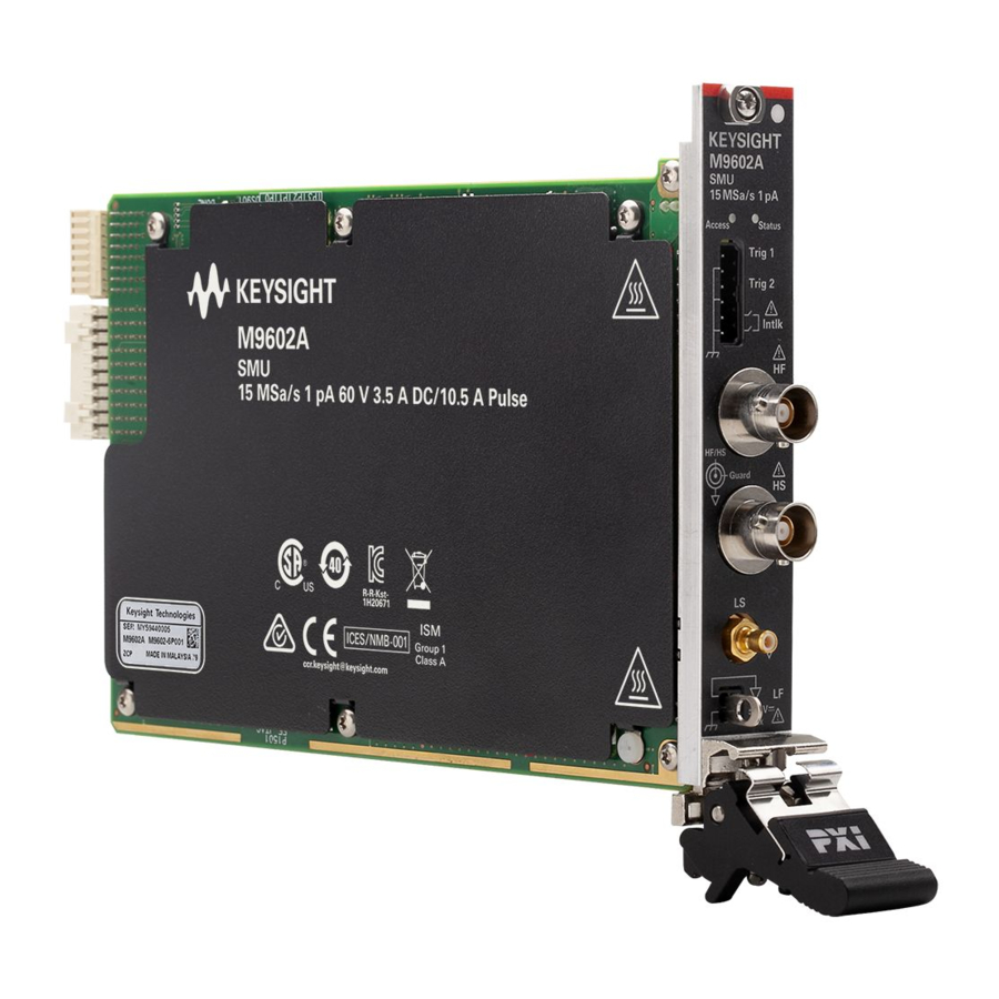
Keysight Connection Expert and a soft front panel (SFP). M9602A PXIe SMU, 15 MSa/s, 1 pA, 60 V, 3.5 A DC/10.5 A pulse • M9603A PXIe Precision SMU, 15 MSa/s, 100 fA, 60 V, 3.5A DC/10.5 A pulse •... -
Page 8: Step 1: Unpack And Inspect The Module
Step 1: Unpack and Inspect the Module Step 1: Unpack and Inspect the Module Keysight’s PXIe chassis and instrument modules are shipped in materials which prevent static electricity damage. The modules should only be removed from the packaging in an anti-static area ensuring that correct anti-static precautions are taken. -
Page 9: Before Unpacking
Step 1: Unpack and Inspect the Module Before Unpacking Keysight M9602A/M9603A module is designed to meet IEC/EN61010-1 and must only be installed in the PXIe chassis which is certified by a Nationally Recognized Testing Laboratory. The PXIe chassis must already be installed on a static-safe workbench so that you can install the module soon after unpacking. -
Page 10: Return The Module For Service
Should it become necessary to return a module for repair or service, follow the steps below. 1. Review the warranty information shipped with your product. 2. Contact Keysight to obtain a Return Material Authorization (RMA) and return address. For assistance in finding Keysight contact information, visit www.keysight.com/find/assist. -
Page 11: Step 2: Verify Shipment Contents
Certification of calibration (without test data) Short bar Connector-terminal block 2.5 mm 6-terminal Consumable supplies of the M9602A/M9603A are shown below. Table 1-2 Consumable Supplies Part number Description Quantity M9601-87001 Short bar M9601-87002 Connector-terminal block 2.5 mm 6-terminal Keysight M9602A/M9603A Startup Guide, Edition 3... -
Page 12: Step 3: Install The Software
Controller (desktop PC, laptop PC, rackmount PC, or PXIe embedded • computer) installed with Keysight IO Libraries Suite Keysight PXIe chassis which has already been set up • For setting up the controller and the PXIe chassis, refer to the PXIe chassis documentation. -
Page 13: Step 4: Install The Module
Generic module installation is shown below. It may not reflect your module’s actual size and chassis placement. Install the leftmost module first and continue installing modules from left to right according to the image below. Keysight M9602A/M9603A Startup Guide, Edition 3... - Page 14 For more information on the module installation, refer to the PXIe chassis documentation. Ensure that filler panels are installed in all empty slots. Missing filler panels will impact cooling of the chassis and may cause RFI (radio frequency interference) with other devices. Keysight M9602A/M9603A Startup Guide, Edition 3...
- Page 15 Immediately after powering down, the M9602A/M9603A module side panels may be hot to cause a burn. Before removing the module from the chassis, take a time for dissipating the heat, and make sure that the side panels are cool enough to touch. Keysight M9602A/M9603A Startup Guide, Edition 3...
-
Page 16: Step 5: Verify Operation Of The Module
Device Manager. The module should be visible in the device tree. The controller might request a reboot. Reboot the controller, if requested. 6. Check if the module is also visible in the Keysight Connection Expert; e.g. via Start menu > Keysight Connection Expert. -
Page 17: To Update The Firmware
If a firmware update is available, perform the following procedure to update the firmware of the M9602A/M9603A modules. 1. Click Start menu > Keysight M960x Source Measure Unit > M960x SFP. The Connect to Instrument dialog box will open. 2. In the list on the window, highlight the M9602A/M9603A modules to connect, and click Connect to launch the Keysight M960x PXIe Source Measure Unit Soft Front Panel (the M960x SFP). -
Page 18: To Perform Self Test
Before performing the self test, turn the instrument output off and disconnect cables from the measurement terminals. 1. Click Start menu > Keysight M960x Source Measure Unit > M960x SFP. The Connect to Instrument dialog box will open. 2. In the list on the window, highlight the M9602A/M9603A modules to connect, and click Connect to launch the M960x SFP. -
Page 19: Front Panel Features
Figure 1-1 M9602A/M9603A Front Panel Status indicator Access indicator Trigger and Interlock External trigger 1 Frame/chassis External trigger 2 High force Frame/chassis Interlock high Interlock low (Frame/chassis) High sense Low sense Low force Frame/chassis Keysight M9602A/M9603A Startup Guide, Edition 3... -
Page 20: Measurement Terminals
2-wire connection using the High force and Low force terminals or 4-wire connection (Kelvin connection) using the High force, Low force, High sense and Low sense terminals. The Kelvin connection is effective in high current measurement. Keysight M9602A/M9603A Startup Guide, Edition 3... - Page 21 Confirm that the Status indicator does not turn yellow. • Open the fixture cover or the shielding box access door (open interlock). • Discharge any capacitors connected to a channel. • Warn persons working around the instrument about dangerous conditions. • Keysight M9602A/M9603A Startup Guide, Edition 3...
- Page 22 Vérifiez que la LED Status ne devienne pas jaune. • Ouvrez le couvercle d'appareil ou la protection du boîtier de la porte • d'accès (verrouillage ouvert). Déchargez tous les condensateurs connectés au réseau. • Déchargez tous les condensateurs connectés au réseau. • Keysight M9602A/M9603A Startup Guide, Edition 3...
- Page 23 This connector is used for the 4-wire connection (Kelvin connection). If you make the 2-wire connection, open this connector. The connector has two conductors: core and shield. These conductors Low sense are the measurement terminals as shown in the following figure. Low force Keysight M9602A/M9603A Startup Guide, Edition 3...
- Page 24 40 V. Failure to heed this caution may result in damage to the M9602A/M9603A. Do not apply current or voltage to the frame/chassis terminal. Doing so will damage the M9602A/M9603A. Keysight M9602A/M9603A Startup Guide, Edition 3...
-
Page 25: Trigger And Interlock Terminals
Figure 1-1. You can connect these terminals using a connector-terminal block furnished with the M9602A/ M9603A and ferrule terminal cables such as Keysight PX0101A-001 or PX0101A-002 BNC to ferrule terminal cable. Trig 1 and Trig 2 External trigger 1 and 2 terminals These terminals are used to make synchronization with other modules or instruments. -
Page 26: Connecting A Dut
électrique et toute brûlure. Utilisez des gants et des outils. Prévoyez également du temps pour la décharge et la radiation. Set the instrument output off when changing the connections. If not, the DUT may be damaged. Keysight M9602A/M9603A Startup Guide, Edition 3... -
Page 27: 2-Wire Connection Or 4-Wire Connection
Connecting the force and sense lines together at the terminal of the DUT minimizes the measurement error by the residual resistance of the test leads or cables. This connection is effective for low resistance measurements and high current measurements. Keysight M9602A/M9603A Startup Guide, Edition 3... - Page 28 Short bar High force High sense Low sense Low force Frame/chassis Figure 1-3 2-Wire Connection and 4-Wire Connection High force High force High sense Low sense Low force Low force 2-wire connection 4-wire connection Keysight M9602A/M9603A Startup Guide, Edition 3...
-
Page 29: Floating
Utiliser également des accessoires qui sont conformes à la norme IEC 61010-031. Toutes les bornes et les conducteurs prolongés doivent être isolés en utilisant des bouchons d'isolation, des manchons, etc. Keysight M9602A/M9603A Startup Guide, Edition 3... -
Page 30: Guarding
1-4. The guard shield is necessary to prevent the leakage current in the measurement environment including extension cables, test fixtures, shielding boxes. It is important to use a triaxial cable such as Keysight PX0102A-001 Low noise triaxial cable (1.5 m). The buffer amplifier keeps the potential of the Guard (inner shield of triaxial cable) at the same potential as the High force (core), so that the current does not flow between the core and the inner shield. -
Page 31: Installing Interlock Circuit
For information on setting the threshold level by programming, refer to the driver references. Figure 1-5 Interlock Circuit Shielding box Access door Connector-terminal block Ferrule terminal Interlock high Interlock low (Frame/chassis) Mechanical switches Keysight PX0101A-001 or equivalent Insulator Keysight M9602A/M9603A Startup Guide, Edition 3... - Page 32 Mechanical switch (Keysight N1254A-402 or equivalent), 2 ea. • Connector-terminal block 2.5 mm 6-terminal, 1 ea. • BNC to ferrule terminal cable (Keysight PX0101A-001 (1.5 m), PX0101A-002 • (3.0 m), or equivalent), 1 ea. BNC connector (jack to soldering terminals), 1 ea.
- Page 33 Installing Interlock Circuit You can also connect the mechanical switches directly to the connector-terminal block by connection wires and ferrule terminals. Figure 1-6 Dimension of the Interlock Switch (Keysight N1254A-402) 10.3 4.75 35.6 Switch off 15.3 10.3 15.9 18.8 C OM 22.2...
-
Page 34: Maintenance
Do not use too much liquid in cleaning the PXIe chassis. Water can enter the PXIe chassis panels and damage sensitive electronic components. Make sure that the PXIe chassis is completely dry before reconnecting the power cord. Keysight M9602A/M9603A Startup Guide, Edition 3... -
Page 35: Self Test
Maintenance Self Test Keysight M9602A/M9603A provides the self test function to check the operation. It is recommended to perform the self test for the following condition or purpose. If emergency shutdown occurs. • In this condition, both the Access and Status indicators turn red. The shutdown condition will be solved after passing the self test. -
Page 36: Calibration
Maintenance To perform 1. Click Start menu > Keysight M960x Source Measure Unit > M960x SFP. The self calibration Connect to Instrument dialog box will open. 2. From the list on the window, highlight the M9602A/M9603A modules to connect and click Connect to launch the Keysight M960x Source Measure Unit Soft Front Panel. -
Page 37: Function Overview
(DUT) due to overcurrent or overvoltage. The voltage Limit is for current source, and the current Limit is for voltage source. Operation Mode The M9602A/M9603A module provides two operation modes for source output. The following modes can be selected depending on DUT or application. Keysight M9602A/M9603A Startup Guide, Edition 3... -
Page 38: Output Filter
Figure 1-7. You can control the pulse output and measurement timing by setting trigger parameters. Figure 1-7 Variety of Sweep Outputs Constant Linear single sweep Linear double sweep List sweep V or I Pulse Keysight M9602A/M9603A Startup Guide, Edition 3... -
Page 39: Sweep Output
This mode is available for source output except linear sweep output. BEST Best range The minimum range covering the whole sweep output is automatically selected. This mode is available for linear sweep output. Keysight M9602A/M9603A Startup Guide, Edition 3... -
Page 40: Seamless Current Measurement Ranging
M9602A/M9603A supports the ARM-TRIGger model in 1999 SCPI Command Reference. This trigger model is independently applied to two device actions: Transient (source output) and Acquire (measurement). These two device actions can start simultaneously or separately. Keysight M9602A/M9603A Startup Guide, Edition 3... -
Page 41: Measurement Time
PXI1, ..., PXI7). Measurement Time The measurement time depends on the aperture time, measurement range, and other measurement conditions. It can be expressed by the following equation. Measurement time = Aperture time + Overhead time Keysight M9602A/M9603A Startup Guide, Edition 3... -
Page 42: Remote Transient Voltage Measurement
10 mA and 10 mA range. Otherwise, the output value is set to 10 mA, and the output range is set to 10 mA range. Normal Output switch: off Source function: voltage source Keysight M9602A/M9603A Startup Guide, Edition 3... -
Page 43: Interlock
If the interlock terminals are opened in a high voltage condition over the • threshold voltage level, the output voltage is immediately set to 0 V, and the output switch is set to off. Keysight M9602A/M9603A Startup Guide, Edition 3... -
Page 44: Protection From Emergency
If the emergency condition continues for a certain period of time after the immediate output-off, the emergency shutdown occurs. If the emergency shutdown occurs, perform the self test. See “Self Test” on page Keysight M9602A/M9603A Startup Guide, Edition 3... - Page 46 This information is subject to change without notice. © Keysight Technologies 2020, 2021 Edition 3, May 2021 *M9603-90000* M9603-90000 www.keysight.com...
Need help?
Do you have a question about the M9602A PXIe and is the answer not in the manual?
Questions and answers