Table of Contents
Advertisement
Quick Links
Form Number: F-1031
Issue Date: Aug 1, 2017
Section: 2447
Revision Date: Sept 16, 2022
AQUIS™ Foam System
Installation, Operation, and Maintenance Instructions
AQUIS 1.5, AQUIS 3.0, and AQUIS 6.0
Waterous Company • 125 Hardman Avenue South • South Saint Paul, MN 55075 • (651) 450-5000
www.waterousco.com
Advertisement
Table of Contents

Related Manuals for Waterous AQUIS 1.5


Summary of Contents for Waterous AQUIS 1.5
- Page 1 Issue Date: Aug 1, 2017 Section: 2447 Revision Date: Sept 16, 2022 AQUIS™ Foam System Installation, Operation, and Maintenance Instructions AQUIS 1.5, AQUIS 3.0, and AQUIS 6.0 Waterous Company • 125 Hardman Avenue South • South Saint Paul, MN 55075 • (651) 450-5000 www.waterousco.com...
-
Page 2: Table Of Contents
Installation Precautions AQUIS 1.5 Components Disconnecting the Frame Ground AQUIS 3.0 Components Modifying the Foam System AQUIS 1.5 and 3.0—Under the Cover Preparing for the Install AQUIS 6.0 Components Installing the Vented Oil Cap AQUIS 6.0—Under the Cover Determining the Pump Assembly Location Overview Diagram—Typical... - Page 3 Maintenance Calibrating and Setup—Digital OIT Entering the Calibration/Setup Mode Maintenance Schedule Editing the Default Mix Percentage—F1 Servicing the Oil Editing the Units of Measure—F2 Checking the Oil Level Calibrating the Flow Rate—F3 Draining the Oil Enabling System Lockout—F4 Adding Oil Selecting the Concentrate Source—F5 Completing the Oil Change Simulating Water Flow—F6...
-
Page 4: Safety
Refer to instruction • Regularly check for leaks, worn, or deteriorated parts. shipping plug and replace it F-1031-2447 for • Waterous reserves the right to make modifications to the system without detailed information. with the vented oil cap. notice. NOTICE... -
Page 5: Safety Precautions-Continued
Safety Introduction Product Overview Installation Operation Maintenance Troubleshooting Safety Precautions—Continued NOTICE NOTICE Modification Equipment Damage Modifying the equipment • Using the wrong fuse may • can damage components damage the equipment. and void your warranty. Only use the specified fuse •... - Page 6 Safety Introduction Product Overview Installation Operation Maintenance Troubleshooting Safety Precautions—Continued High Current High Pressure Current can cause serious Liquid ejected at high • • pressure can cause injury or death. serious injury. Disconnect the power • Drain the lines before before servicing the pump.
-
Page 7: Introduction
This document is divided into the following sections: Locate and record the model and serial number of the equipment in your Safety application. Have this information available when you call Waterous. This section describes general precautions and alert symbols that are in this document. -
Page 8: Standard Components
Foam Only or Traditional CAFSystems™ ™ ONE STEP ONE STEP™ ™ and Eclipse GEN 2.0 and Eclipse GEN 2.0™ ™ Included Included with with AQUIS 1.5 AQUIS 1.5 AQUIS 3.0 AQUIS 3.0 AQUIS 6.0 AQUIS 6.0 AQUIS 1.5 AQUIS 1.5 AQUIS 3.0... -
Page 9: Optional Components
Dual tank selector kit This kit allows drawing the concentrate from 2 on-board supply tanks, or an on-board tank and an external container. Note: This kit is not available for AQUIS 1.5. Overboard foam pick-up kit This kit includes a pump, a pick-up hose and fittings to transfer concentrate from an external container. -
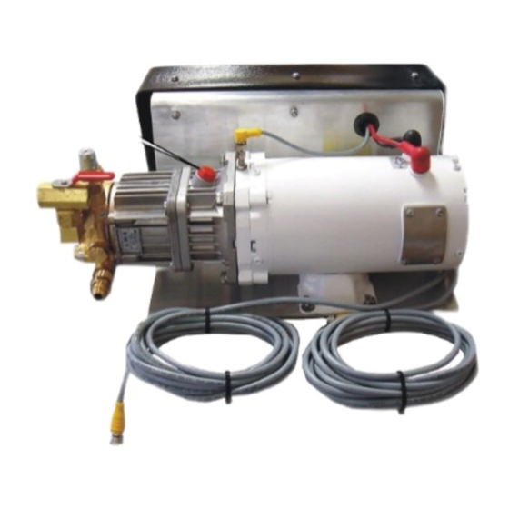
Page 10: Aquis 1.5 Components
Safety Introduction Product Overview Installation Operation Maintenance Troubleshooting AQUIS 1.5 Components Figure 1... - Page 11 Safety Introduction Product Overview Installation Operation Maintenance Troubleshooting AQUIS 1.5 Components Feature Feature Description Description Oil level window This shows the oil level in the pump. Cover This covers the control box and terminal strip. Pump This is the pump assembly.
-
Page 12: Aquis 3.0 Components
Safety Introduction Product Overview Installation Operation Maintenance Troubleshooting AQUIS 3.0 Components Figure 2... - Page 13 Safety Introduction Product Overview Installation Operation Maintenance Troubleshooting AQUIS 3.0 Components Feature Feature Description Description Oil level window This shows the oil level in the pump. Cover This covers the control box and terminal strip. Vented oil cap This is cap replaces the shipping cap. Pump This is the pump assembly.
-
Page 14: Aquis 1.5 And 3.0-Under The Cover
Safety Introduction Product Overview Installation Operation Maintenance Troubleshooting AQUIS 1.5 and 3.0—Under the Cover Figure 3... - Page 15 Safety Introduction Product Overview Installation Operation Maintenance Troubleshooting AQUIS 1.5 and 3.0—Under the Cover Feature Feature Description Description Accessory terminal strip This connects accessories to the control box. Circuit breaker This prevents over-current. Control box This houses the electric components.
-
Page 16: Aquis 6.0 Components
Safety Introduction Product Overview Installation Operation Maintenance Troubleshooting AQUIS 6.0 Components Figure 4... - Page 17 Safety Introduction Product Overview Installation Operation Maintenance Troubleshooting AQUIS 6.0 Components Feature Feature Description Description Oil level window This shows the oil level in the pump. Cover This covers the control box and terminal strip. Pump This is the pump assembly. Vented oil cap This is cap replaces the shipping cap.
-
Page 18: Aquis 6.0-Under The Cover
Safety Introduction Product Overview Installation Operation Maintenance Troubleshooting AQUIS 6.0—Under the Cover Figure 5... - Page 19 Safety Introduction Product Overview Installation Operation Maintenance Troubleshooting AQUIS 6.0—Under the Cover Feature Feature Description Description Accessory terminal strip This connects accessories to the control box. Fuse housing This is the fuse location. Circuit breaker This prevents over-current. HMI/OIT connection This connects the controller to the HMI or OIT.
-
Page 20: Overview Diagram-Typical
Safety Introduction Product Overview Installation Operation Maintenance Troubleshooting Overview Diagram—Typical Note: The graphics in this illustration are intended to help you understand concepts in next sections. Do not use them to determine physical attributes, placement or proportion. -
Page 21: System Overview
Troubleshooting System Overview The following information describes the components the are used in a typical foam system setup. Your application may not include all, or contain additional components than the ones described below. Contact Waterous for more information. Component/Accessory Component/Accessory... -
Page 22: Dual Tank System Overview-Optional
Safety Introduction Product Overview Installation Operation Maintenance Troubleshooting Dual Tank System Overview—Optional Note: The graphics in this illustration are intended to help you understand concepts in next sections. Do not use them to determine physical attributes, placement or proportion. -
Page 23: Dual Tank System Overview-Optional
Dual Tank System Overview—Optional In addition to the typical setup, you can add additional flexibility by incorporating the dual tank option. Below is a description of the additional components used in most applications. Contact Waterous for more information. Component/Accessory Component/Accessory... -
Page 24: Flush System Overview-Optional
Safety Introduction Product Overview Installation Operation Maintenance Troubleshooting Flush System Overview—Optional... -
Page 25: Flush Kit Overview-Optional
You can add the flush kit to the AQUIS to flush the system when necessary. The environment, the concentrate used, and other factors determine if or when you need to flush the foam pump. Refer to the apparatus and/or concentrate manufacturer to determine a protocol for flushing. Contact Waterous for more information. -
Page 26: Component Overview
Figure Hose lines distribute the concentrate between the foam system components. This cable is an M12, 5-pin connector. Hoses are not supplied in this kit. Contact Waterous for more information. Cable Extension Supply Hose Extension cables extend the routing distance of the flowmeter or OIT/HMI The supply hose routes the concentrate from the supply tank to pump. -
Page 27: Usb Port
Figure Supply Tank Level Sensor This sensor alerts you when the concentrate reaches a predetermined level in the supply tank. A sensor not supplied in this kit. Contact Waterous for information about obtaining a sensor. Figure 8 Wye Fitting with Strainer... -
Page 28: Concentrate Inject Check Valve
Safety Introduction Product Overview Installation Operation Maintenance Troubleshooting Concentrate Inject Check Valve Inject/Bypass Valve This check valve is installed in the injector fitting and prevents the foam solution Use the inject/bypass valve (Figure 12) to manually direct the concentrate as from entering the concentrate hose (Figure 10). -
Page 29: Flowmeter Tee
Safety Introduction Product Overview Installation Operation Maintenance Troubleshooting Flowmeter Tee The flowmeter tee houses the flowmeter and measures the amount of water flowing from the waterway supply line (Figure 13). 1. Flowmeter 2. Tee body Figure 13 The flowmeter tee is available in the following configurations: 2-inch tee 2-inch tee Inlet/Outlet:... -
Page 30: Master Waterway Check Valve
Safety Introduction Product Overview Installation Operation Maintenance Troubleshooting Master Waterway Check Valve Concentrate Injector This valve ensures that the water and concentrate flow in one direction (Figure 14). It prevents the mix flowing into the water tank or pump. The check This fitting injects the concentrate into the waterway to create the valve is available in the following configurations: solution in the apparatus... -
Page 31: Foam Manifold
3. Manifold 1. Drain Figure 16 Figure 17 Inlet/Outlet Inlet/Outlet 2-1/2 inches Waterous 4-bolt flange (4-3/8 B.C.) Combination: Victaulic (2 inches) and FNPT (1-1/2 inches) Combination: Victaulic (2-1/2 inches) and FNPT (2 inches) Combination: Victaulic (3 inches) and FNPT (2-1/2 inches) -
Page 32: Pressure Regulator Valve
Do not tamper with the pressure regulator valve or operate the pump with a damaged pressure regulator valve. • Use Figure 18 to locate the regulator valve on the AQUIS 1.5. Figure 19 • Use Figure 19 to locate the regulator valve on the AQUIS 3.0. -
Page 33: Operator Interface Terminal (Oit)
Safety Introduction Product Overview Installation Operation Maintenance Troubleshooting Operator Interface Terminal (OIT) Manual OIT The OIT enables or disables the foam system operation and adjusts the amount The manual OIT (Figure 22) communicates with the pump controller to of concentrate that is injected into the waterway. It is available in digital and perform the following functions: manual versions. -
Page 34: Accessory Terminal Strip
Safety Introduction Product Overview Installation Operation Maintenance Troubleshooting Accessory Terminal Strip The terminal strip adds accessories and functionality to the pump. The terminal strip (Figure 24) is located under the cover on the controller (Figure 23). Figure 23 Figure 24 Description Description Comments... -
Page 35: Installation
The foam system is intended to be installed by a person or persons with The foam system components are designed to operate mounted to the basic knowledge of installing similar equipment. Contact Waterous with the mounting bracket. Removing the components from the mounting questions about installing the foam system. -
Page 36: Preparing For The Install
Safety Introduction Product Overview Installation Operation Maintenance Troubleshooting Preparing for the Install Installing the Vented Oil Cap Consider the information below before you begin installing the foam system. NOTICE • Determine the install location for the components, consider wire and hose routing, mounting locations and maintenance requirements. -
Page 37: Determining The Pump Assembly Location
Safety Introduction Product Overview Installation Operation Maintenance Troubleshooting Determining the Pump Assembly Location Installing the Pump Assembly Use the following guidelines to determine a location to mount the pump The foam system components are designed to operate as installed on the assembly: mounting bracket (Figure... -
Page 38: Installing The Oit
Safety Introduction Product Overview Installation Operation Maintenance Troubleshooting Installing the OIT Connecting M12 Cables to the Control Box 1. Locate one end of the M12, 8-pin cable. 1. Remove the cover. Refer to: "Removing the Cover" on page 2. Align the pins and key in the plug to the connector. 2. -
Page 39: Installing The Master Waterway Check Valve
3. Use cable ties to secure the cable to the apparatus. Note: Do not secure the wire harness to hot or moving parts. Note: Waterous for information about obtaining a cable extension. 4. Install the cover. Refer to: "Installing the Cover" on page Installing the Master Waterway Check Valve "Overview Diagram—Typical"... -
Page 40: Installing The Flowmeter Tee
Safety Introduction Product Overview Installation Operation Maintenance Troubleshooting Installing the Flowmeter Tee 2. Install the inlet side of the manifold towards the water pump. Important: Installing the foam manifold at more than a ± 15° tilt may 1. Orient the flowmeter with the connector at the top (Figure 32). -
Page 41: Installing The Supply Hose
3. Use cable ties to secure the hoses to the apparatus. Note: Do not pinch or kink the hose. Note: Do not secure the hose to hot or moving parts. Note: An optional hose kit is available, contact your Waterous for more information. Figure 32... -
Page 42: Connecting The Power Supply
30 A to 100 A to operate. Ensure the power source used meets the following specifications: Model Model Voltage Voltage Amps Amps AQUIS 1.5 AQUIS 1.5 12 Vdc 50 A 24 Vdc 30 A AQUIS 3.0 AQUIS 3.0... - Page 43 Safety Introduction Product Overview Installation Operation Maintenance Troubleshooting The electrical requirements vary based on your specific application. The 4. Connect the other end of the positive (+) cable to the positive (+) post of the following tables are calculated using the SAE J1128 standard with a 2% drop. foam pump (Figure 34).
-
Page 44: Installing The Tank Level-Sensor Cable
Safety Introduction Product Overview Installation Operation Maintenance Troubleshooting Installing the Tank Level—Sensor Cable Installing the Wye Fitting with Strainer 1. Connect the sensor wires to the foam concentrate terminal strip. The wye fitting with strainer is installed in-line with the supply shutoff valve and the supply hose. -
Page 45: Installing The Concentrate Inject Check Valve
Safety Introduction Product Overview Installation Operation Maintenance Troubleshooting Installing the Concentrate Inject Check Valve Installing the Drain Lines 1. Use the arrow on the check valve to determine the flow direction of the Install a dedicated line to the drain port on the check valve or manifold to concentrate (Figure 37). -
Page 46: Calibrating-Manual Oit
Safety Introduction Product Overview Installation Operation Maintenance Troubleshooting Calibrating—Manual OIT Calibrating and Setup—Digital OIT Entering the Calibration/Setup Mode 1. Rotate the (FOAM % dial) to 0. 1. Press and hold the (SELECT button). 2. Press and hold the (ON/OFF button) for 6 seconds. 3. -
Page 47: Editing The Default Mix Percentage-F1
Safety Introduction Product Overview Installation Operation Maintenance Troubleshooting Editing the Default Mix Percentage—F1 Editing the Units of Measure—F2 1. Enter the calibration/setup mode. Refer to: 1. Enter the calibration/setup mode. Refer to: "Entering the Calibration/Setup Mode" on page 46. "Entering the Calibration/Setup Mode" on page 2. -
Page 48: Calibrating The Flow Rate-F3
(FOAM button) to save the value and exit the display value to match the value that you measured. calibration and setup mode. Note: Contact Waterous for more information about locking and • When the (low flow) value is displayed, an insufficient unlocking the OIT. -
Page 49: Selecting The Concentrate Source-F5
1. Enter the calibration/setup mode. Refer to: "Entering the Calibration/Setup Mode" on page Use this mode to test and verify the foam system operation. This function is available for the AQUIS 1.5 with digital head, AQUIS 3.0 and 2. Navigate to (F5 parameter). -
Page 50: Setting Default Mix Percent For B Foam-F7
Safety Introduction Product Overview Installation Operation Maintenance Troubleshooting Setting Default Mix Percent for B Foam—F7 Default mix percentage Default mix percentage 1. Enter the calibration/setup mode. Refer to: 0.1% 0.1% 0.2% 0.2% 0.3% 0.3% 0.4% 0.4% .05% .05% 0.6% 0.6% 0.7% 0.7% 0.8% 0.8% 0.9% 0.9% 1.0%... -
Page 51: Operation
The foam system is intended to be operated by a person, or persons, with Components in the foam system may become hot during operation. the basic knowledge of operating similar equipment. Contact Waterous with questions about operating the foam system. Be aware of the following... -
Page 52: Operating The Manual Oit
Safety Introduction Product Overview Installation Operation Maintenance Troubleshooting Operating the Manual OIT Operating in Normal Mode In normal operating mode, the OIT uses information from the flowmeter and the FOAM % dial to produce the desired mix. Starting and Stopping the Pump 1. -
Page 53: Operating In Manual Mode
Safety Introduction Product Overview Installation Operation Maintenance Troubleshooting Operating in Manual Mode Understanding the LED Indicators The foam system can operate in manual mode as required by the NFPA Blue LED regulation. While in manual mode, the foam system injects concentrate into •... -
Page 54: Operating The Digital Oit
Safety Introduction Product Overview Installation Operation Maintenance Troubleshooting Operating the Digital OIT 1 Mounting hardware The hardware mounts OIT to the apparatus. 2 FOAM button This button starts and stops the pump operation. 3 Display The display shows 4 characters that represent the value for the current mode. -
Page 55: Powering Up The Oit
Safety Introduction Product Overview Installation Operation Maintenance Troubleshooting Powering Up the OIT Operating in Manual Mode The apparatus manufacturer determines how the foam system powers up in The foam system can operate in manual mode as required by the NFPA your application. -
Page 56: Operating And Disabling Manual Mode
Safety Introduction Product Overview Installation Operation Maintenance Troubleshooting Operating and Disabling Manual Mode Displaying Default Mix Percent In manual mode you can start or stop the pump and increase or decrease the foam percent. 1. Press the (SELECT button) until the PERCENT LED illuminates. 1. -
Page 57: Operating The Inject/Bypass Valve
Follow the instructions from the apparatus manufacturer to drain the valve. 1. Make the apparatus ready for flushing. Refer to the documentation Contact Waterous for more information. provided by the apparatus manufacturer for more information. 2. Enable manual mode on the OIT. Refer to: •... -
Page 58: Maintenance Schedule
Safety Introduction Product Overview Installation Operation Maintenance Troubleshooting Maintenance Schedule Perform the following procedures at the recommended intervals. Every 8 Every 8 Every 50 Every 50 Every 500 Every 500 Operation Operation Hours Hours Hours Hours Hours Hours Check the oil level High Pressure Inspect the hoses and fittings Clean the wye fitting with strainer... -
Page 59: Adding Oil
2,and Figure 2. Use the chart below to determine the oil capacity of your model. Model Model Oil Capacity Oil Capacity AQUIS 1.5 AQUIS 1.5 6.1 oz (0.18 L) AQUIS 3.0 AQUIS 3.0 10.8 oz (0.32 L) AQUIS 6.0 AQUIS 6.0 18.9 oz (0.56 L) -
Page 60: Replacing A Fuse
Safety Introduction Product Overview Installation Operation Maintenance Troubleshooting Replacing a Fuse Tripping and Resetting the Circuit Breaker Note: Only use a fuse with the following specifications: 1. Remove the cover. Refer to: "Removing the Cover" on page • 20 mm x 5 mm 2. -
Page 61: Cleaning The Wye Fitting With Strainer
Safety Introduction Product Overview Installation Operation Maintenance Troubleshooting Cleaning the Wye Fitting with Strainer Inspecting the Hoses and Fittings Clean the wye fitting every 50 hours of use. Check the hoses and fittings every 50 hours of use. 1. Close the shutoff valve at the supply tank. •... -
Page 62: Troubleshooting
Safety Introduction Product Overview Installation Operation Maintenance Troubleshooting Trouble Shooting Chart Symptom Symptom Possible Cause Possible Cause Solution Solution The foam pump is operating but not The foam pump is not primed. Prime the foam pump. producing flow. The concentrate tank is empty. Add concentrate to the tank. - Page 63 There is a communication error between the OIT and the controller. Verify that the pins on the cable are not bent, then replace the cable if they are damaged. Contact Waterous to replace the control box. The foam concentrate is entering the Concentrate was poured into the water tank.
- Page 64 Waterous Company 125 Hardman Avenue South South Saint Paul, MN 55075 (651) 450-5000 www.waterousco.com...
Need help?
Do you have a question about the AQUIS 1.5 and is the answer not in the manual?
Questions and answers