Waterous CM Series Installation Manual
Fire pumps
Hide thumbs
Also See for CM Series:
- Overhaul instructions (61 pages) ,
- Overhaul instructions (70 pages) ,
- Operation and maintenance manua (28 pages)

Related Manuals for Waterous CM Series


Summary of Contents for Waterous CM Series
- Page 1 Form Number: F-3003 Issue Date: Jan 5, 2023 Revision Date: Feb 6, 2023 CM Series Fire Pumps Installation Waterous Company • 125 Hardman Avenue South • South Saint Paul, MN 55075 • (651) 450-5000 www.waterousco.com...
-
Page 3: Table Of Contents
Installing the Transmission Drain Lines—CMUK Product Overview Installing the Transmission Drain Lines—CMPA/CMUPA CM Series Pumps—Drive Options Installing the Transmission Drain Lines—CMC22/CMUC22 CM Series Pumps—Intake and Discharge Flanges Installing the Transfer Valve Actuator—Manual Version CMD/CMUD Mounting the Control Panel CMK/CMUK Installing the Handle... -
Page 4: Safety
Before Operation • Be aware that these instructions are only guidelines and are not meant to be definitive. Contact Waterous when you have questions about the equipment. • Read and understand all the • Do not install the equipment if you are not familiar with the tools and skills needed to safely perform the required procedures—proper installation is the... - Page 5 Safety Introduction Product Overview Installation NOTICE High Current Freeze Damage • Do not allow fluid in the • Current can cause lines to freeze. serious injury or death. • Remove all freezable fluid • Disconnect power before from the lines before servicing the electronic storing the apparatus.
- Page 6 Safety Introduction Product Overview Installation High Pressure High Pressure • Liquid ejected at high • Discharge ejected at high pressure can cause serious pressure can cause injury and damage. serious injury. • Direct discharge away from • Do not operate beyond people and equipment.
-
Page 7: Introduction
Product Overview Installation Using this Document Use this document to install your Waterous equipment. Understand the following conditions before continuing with the document: Use the guidelines below when viewing this document. • The instructions may refer to options or equipment that you may not have Viewing the Document Electronically purchased with your system. -
Page 8: Cm Series Pumps-Drive Options
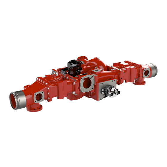
CM Series Pumps—Drive Options CM Series pumps are midship-mounted centrifugal pumps with multiple impellers. Depending on the model, pump capacity can range from 500 to 2,250 GPM (1,900 to 8,550 LPM). CM and CMU pumps are available with direct drive or one of the following transmissions: C22 (rear- or front-mounted), K, or PA (rear- mounted only). -
Page 9: Cm Series Pumps-Intake And Discharge Flanges
CM Series Pumps—Intake and Discharge Flanges CM Series pumps are available with angle-compensated or non-angle-compensated front and side discharge flanges—pump without angle compensation shown below. Pumps with angle compensation feature a front discharge flange angled at 4° and side discharge flanges with holes machined at a 4° rotation. This option ensures that the discharges align with the operator panel after installation. -
Page 10: Cmd/Cmud
Safety Introduction Product Overview Installation CMD/CMUD Feature Feature Description Description Body assembly The body assembly consists of the volute body and volute cover. Intake adapter This connects the pump to the water source. Intake mounting pad This is where the installer-supplied angle bracket is attached to the pump. Impeller shaft This connects the pump to the driveline. -
Page 11: Cmk/Cmuk
Safety Introduction Product Overview Installation CMK/CMUK Feature Feature Description Description Body assembly The body assembly consists of the volute body and volute cover. Intake adapter This connects the pump to the water source. Intake mounting pad This is where the installer-supplied angle bracket is attached to the pump. Transmission This increases the speed of the pump. -
Page 12: Cmpa/Cmupa
Safety Introduction Product Overview Installation CMPA/CMUPA Feature Feature Description Description Body assembly The body assembly consists of the volute body and volute cover. Intake adapter This connects the pump to the water source. Intake mounting pad This is where the installer-supplied angle bracket is attached to the pump. Transmission This increases the speed of the pump. -
Page 13: Cmc22/Cmuc22
Safety Introduction Product Overview Installation CMC22/CMUC22 Feature Feature Description Description Body assembly The body assembly consists of the volute body and volute cover. Intake adapter This connects the pump to the water source. Intake mounting pad This is where the installer-supplied angle bracket is attached to the pump. Transmission This increases the speed of the pump and can transfer incoming power to either the pump or driveline. -
Page 14: Cmc22/Cmuc22 (Front-Mounted)
Safety Introduction Product Overview Installation CMC22/CMUC22 (Front-Mounted) Feature Feature Description Description Body assembly The body assembly consists of the volute body and volute cover. Intake adapter This connects the pump to the water source. Intake mounting pad This is where the installer-supplied angle bracket is attached to the pump. Front support mounting hole This is where the installer-supplied front support bracket is attached to the pump. - Page 15 Notes...
-
Page 16: Transfer Valve Actuator Control Panel-Manual Version
Safety Introduction Product Overview Installation Transfer Valve Actuator Control Panel—Manual Version Feature Feature Description Description Mounting holes These are used to mount the actuator control panel to the apparatus. Handle This handle moves the valve into the pressure or volume position. Bare lead—black This connects to ground. -
Page 17: Manual Transfer Valve Actuator
Safety Introduction Product Overview Installation Manual Transfer Valve Actuator Feature Feature Description Description Connector This connects to the extension cable that goes between the control panel and encoder—DT04-4P. Encoder This monitors the position of the actuator and sends it to the control panel. Gear case shaft This connects to the control rod that goes between the control panel and actuator. -
Page 18: Encoder Extension Cable
Safety Introduction Product Overview Installation Encoder Extension Cable Feature Feature Description Description Connector This connects to the control panel —DT04-4P. Cable The length of this cable is 120 inches (3,048 mm). Connector This connects to the encoder—DT06-4S. -
Page 19: Transfer Valve Actuator Control Panel-Electric Version
Safety Introduction Product Overview Installation Transfer Valve Actuator Control Panel—Electric Version TRANSFER VALVE PRESSURE VOLUME Feature Feature Description Description Mounting holes These are used to mount the actuator control panel to the apparatus. Pressure button This button moves the valve into the pressure position. Volume button This button moves the valve into the volume position. -
Page 20: Electric Transfer Valve Actuator
Safety Introduction Product Overview Installation Electric Transfer Valve Actuator Feature Feature Description Description Gear motor This creates the force to move the valve. Encoder This monitors the position of the actuator and sends it to the control panel. Connector This connects to the extension cable that goes between the control panel and encoder—DT04-4P. Connector This connects to the motor extension cable that goes between the power relay module and gear motor. -
Page 21: Power Relay Module
Safety Introduction Product Overview Installation Power Relay Module Feature Feature Description Description Potting box This houses the module's electronic components. Mounting holes These are used to mount the power relay module to the apparatus. Connector This connects to the motor extension cable that goes between the power relay module and actuator motor. Connector This connects to the power relay module—DT06-4S. -
Page 22: Motor Extension Cable
Safety Introduction Product Overview Installation Motor Extension Cable Feature Feature Description Description Connector This connects to the actuator motor. Cable The length of this cable is 120 inches (3,048 mm). Connector This connects to the power relay module. -
Page 23: Transfer Valve Actuator Manual Override-Optional
Safety Introduction Product Overview Installation Transfer Valve Actuator Manual Override—Optional Feature Feature Description Description Mounting holes These are used to mount the manual override control panel to the apparatus. Crank handle This handle moves the valve into the pressure or volume position if the electric actuator fails. -
Page 24: Installation
This equipment is intended to be installed by a person or persons with the basic This equipment is intended to operate as designed. Do not remove, modify, or knowledge of installing similar equipment. Contact Waterous with questions change the components in the system. Doing so will void your warranty. -
Page 25: Cmd/Cmud-Installing The Pump
Safety Introduction Product Overview Installation CMD/CMUD—Installing the Pump Use the illustration and instructions to install the CMD or CMUD pump assembly. Note: Install the pump where it is accessible for regular maintenance. The pump location must also comply with drive shaft requirements. 1 Create angle brackets to attach to the intake mounting pads. -
Page 26: Cmk/Cmuk-Installing The Pump
Safety Introduction Product Overview Installation CMK/CMUK—Installing the Pump Use the illustration and instructions to install the CMK or CMUK pump assembly. Note: Install the pump where it is accessible for regular maintenance. The pump location must also comply with drive shaft requirements. 1 Create angle brackets to attach to the intake mounting pads. -
Page 27: Cmpa/Cmupa-Installing The Pump
Safety Introduction Product Overview Installation CMPA/CMUPA—Installing the Pump Use the illustration and instructions to install the CMPA or CMUPA pump assembly. Note: Install the pump where it is accessible for regular maintenance. The pump location must also comply with drive shaft requirements. 1 Create angle brackets to attach to the intake mounting pads. -
Page 28: Cmc22/Cmuc22-Installing The Pump
Safety Introduction Product Overview Installation CMC22/CMUC22—Installing the Pump Use the illustration and instructions to install the CMC22 or CMUC22 pump assembly. Note: Install the pump where it is accessible for regular maintenance. The pump location must also comply with drive shaft requirements. 1 Create angle brackets to attach to the intake mounting pads. -
Page 29: Cmc22/Cmuc22 (Front-Mounted)-Installing The Pump
Safety Introduction Product Overview Installation CMC22/CMUC22 (Front-Mounted)—Installing the Pump Use the illustration and instructions to install the front-mounted CMC22 or CMUC22 pump assembly. Note: Install the pump where it is accessible for regular maintenance. The pump location must also comply with drive shaft requirements. 1 Create a front support bracket to attach to the pump's side discharge and the frame rails. -
Page 30: Mounting The Angle Brackets
Safety Introduction Product Overview Installation Mounting the Angle Brackets Use the illustration and instructions to secure the angle brackets to the intake mounting pads. 1 There are 2 holes in each intake mounting pad. Select the holes that best suit your application, then drill corresponding holes into the angle brackets. -
Page 31: Cmc22/Cmuc22 (Front-Mounted)
Safety Introduction Product Overview Installation Mounting the Angle Brackets CMC22/CMUC22 (Front-Mounted) Use the illustration and instructions to secure the front support bracket and angle brackets to the intake mounting pads. 1 Use a cap screw (1/2-13 inch) to secure the front support bracket to the front of the side discharge. -
Page 32: Optional Spring Configuration
Safety Introduction Product Overview Installation Mounting the Angle Brackets Optional Spring Configuration Use the illustration and instructions to secure the angle brackets to the intake mounting pads. Note: Do not use this mounting method if your pump configuration includes a front-mounted C22 transmission or a rear intake adapter on the passenger side. -
Page 33: Mounting The Pump
Safety Introduction Product Overview Installation Mounting the Pump 3-Point Mounting Method Use the illustrations and instructions to secure the angle brackets to the frame rails using the 3-point mounting method. This method is recommended to compensate for vehicle frame twist. 1 After attaching the angle brackets to the intake adapters, position the pump assembly within the frame rails. -
Page 34: 3-Point Mounting Method-Cmc22/Cmuc22 (Front-Mounted)
Safety Introduction Product Overview Installation Mounting the Pump 3-Point Mounting Method— CMC22/CMUC22 (Front-Mounted) Use the illustrations and instructions to secure the angle brackets to the frame rails using the 3-point mounting method. This method is recommended to compensate for vehicle frame twist in applications with front-mounted C22 transmissions. -
Page 35: 4-Point Mounting Method-Optional Spring Configuration
Safety Introduction Product Overview Installation Mounting the Pump 4-Point Mounting Method— Optional Spring Configuration Use the illustrations and instructions to secure the angle brackets to the frame rails using the 4-point spring mounting method. This method allows for approximately 2° of vehicle frame twist. 1 After attaching the angle brackets to the intake adapters, position the pump assembly within the frame rails. -
Page 36: Installing The Pump Drain Lines-Pump Body
Safety Introduction Product Overview Installation Installing the Pump Drain Lines—Pump Body Use the illustration and instructions to install the pump drain lines. Fluid that is susceptible to freezing must be drained from the pump to prevent damage. NOTICE Freeze Damage •... -
Page 37: Installing The Transmission Drain Lines-Cmk
Safety Introduction Product Overview Installation Installing the Transmission Drain Lines—CMK Use the illustration and instructions to install the transmission drain lines. Fluid that is susceptible to freezing must be drained from the transmission to prevent damage. NOTICE Freeze Damage • Do not allow fluid in the lines to freeze. -
Page 38: Installing The Transmission Drain Lines-Cmuk
Safety Introduction Product Overview Installation Installing the Transmission Drain Lines—CMUK Use the illustration and instructions to install the transmission drain lines. Fluid that is susceptible to freezing must be drained from the transmission to prevent damage. NOTICE Freeze Damage • Do not allow fluid in the lines to freeze. -
Page 39: Installing The Transmission Drain Lines-Cmpa/Cmupa
Safety Introduction Product Overview Installation Installing the Transmission Drain Lines—CMPA/CMUPA Use the illustration and instructions to install the transmission drain lines. Fluid that is susceptible to freezing must be drained from the transmission to prevent damage. NOTICE Freeze Damage • Do not allow fluid in the lines to freeze. -
Page 40: Installing The Transmission Drain Lines-Cmc22/Cmuc22
Safety Introduction Product Overview Installation Installing the Transmission Drain Lines—CMC22/CMUC22 Use the illustration and instructions to install the transmission drain lines. Fluid that is susceptible to freezing must be drained from the transmission to prevent damage. NOTICE Freeze Damage • Do not allow fluid in the lines to freeze. - Page 41 Notes...
-
Page 42: Installing The Transfer Valve Actuator-Manual Version
Safety Introduction Product Overview Installation Installing the Transfer Valve Actuator—Manual Version Mounting the Control Panel Use the illustration and instructions to mount the actuator control panel on the operator panel. 1 Create the cutout and drill the mounting holes for the control panel. 2 Insert the control panel wiring through the cutout, then use the mounting hardware to install the control panel. -
Page 43: Installing The Handle
Safety Introduction Product Overview Installation Installing the Transfer Valve Actuator—Manual Version Installing the Handle Use the illustrations and instructions to install the handle onto the manual transfer valve actuator. 1 Slide the thrust bearing onto the remote shaft. 2 Press the remote shaft through the control panel hole, then press the remote body onto the shaft. -
Page 44: Installing The Control Rod
Note: The control rod is usually supplied by the installer and cut to length, but an optional control rod is available from Waterous. 1 Install U-joints onto each end of the control rod, then secure the joints with spirol pins. -
Page 45: Connecting The Components
Safety Introduction Product Overview Installation Installing the Transfer Valve Actuator—Manual Version Connecting the Components Use the illustration and instructions to connect the manual actuator cables. 1 Connect the control panel connector to the extension cable connector. 2 Connect the extension cable connector to the encoder connector. -
Page 46: Installing The Transfer Valve Actuator -Electric Version
Safety Introduction Product Overview Installation Installing the Transfer Valve Actuator —Electric Version Mounting the Control Panel Use the illustration and instructions to mount the actuator control panel on the operator panel. 1 Create the cutout and drill the mounting holes for the control panel. -
Page 47: Mounting The Power Relay Module
Safety Introduction Product Overview Installation Installing the Transfer Valve Actuator —Electric Version Mounting the Power Relay Module Use the illustration and instructions to mount the power relay module on the operator panel. 1 Drill the mounting holes for the power relay module. -
Page 48: Connecting The Components
Safety Introduction Product Overview Installation Installing the Transfer Valve Actuator—Electric Version Connecting the Components Use the illustration and instructions to connect the cables for the electric actuator assembly. 1 Connect the control panel connector to the extension cable connector. 2 Connect the extension cable connector to the encoder connector. -
Page 49: Installing The Transfer Valve Actuator -Manual Override
Safety Introduction Product Overview Installation Installing the Transfer Valve Actuator —Manual Override Mounting the Control Panel Use the illustration and instructions to mount the manual override control panel on the operator panel. Note: The manual override is optional with the electric transfer valve actuator. -
Page 50: Installing The Crank Handle
Safety Introduction Product Overview Installation Installing the Transfer Valve Actuator—Manual Override Installing the Crank Handle Use the illustrations and instructions to install the handle onto the manual override. 1 Slide the thrust bearing onto the remote shaft. 2 Press the remote shaft through the control panel hole, then press the remote body onto the shaft. -
Page 51: Installing The Control Rod
Note: The control rod is usually supplied by the installer and cut to length, but an optional control rod is available from Waterous. 1 Install U-joints onto each end of the control rod, then secure the joints with spirol pins. -
Page 52: Cmcgv/Cmucgv-Building The Isolation Valve Controls
Safety Introduction Product Overview Installation CMCGV/CMUCGV—Building the Isolation Valve Controls Use the illustration and instructions to build the installer-supplied manual control components for the isolation valve. Note: Certain parts have been removed from the illustration to provide a clear view of the equipment being discussed. -
Page 53: Installing The Anodes And Intake Screens
Safety Introduction Product Overview Installation Installing the Anodes and Intake Screens Use the illustrations and instructions to install the optional anodes and intake screens for corrosion protection. Anodes should be mounted on the intake plumbing, but can be mounted on the discharge plumbing if no intake mounting pads are available. -
Page 54: Tachometer Connection
Transmission Model Transmission Model Capacity (qt/L) Capacity (qt/L) Lubricant Lubricant is available from Waterous. C22C, C22D, ATF (all climates), SAE 20 C22E, C22F Oil 300 SSU at 100°F with service classification SA, SB, SC (ambient temperatures over 90°F or 32°C) - Page 55 Notes...
- Page 56 Waterous Company 125 Hardman Avenue South South Saint Paul, MN 55075 (651) 450-5000 www.waterousco.com...
Need help?
Do you have a question about the CM Series and is the answer not in the manual?
Questions and answers