Sign In
Upload
Manuals
Brands
Waterous Manuals
Firefighting Equipment
AQUIS 3.0
Waterous AQUIS 3.0 Manuals
Manuals and User Guides for Waterous AQUIS 3.0. We have
2
Waterous AQUIS 3.0 manuals available for free PDF download: Installation, Operation And Maintenance Instructions
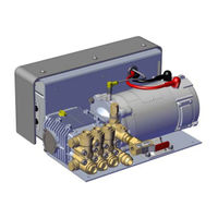
Waterous AQUIS 3.0 Installation, Operation And Maintenance Instructions (90 pages)
Foam System
Brand:
Waterous
| Category:
Firefighting Equipment
| Size: 10.87 MB
Table of Contents
Table of Contents
2
Safety
4
Safety Precautions
4
Safety Precautions-Continued
5
Introduction
7
Using this Document
7
Viewing the Document Electronically
7
Printing the Document
7
Locating the Serial Number
7
Product Overview
8
Standard Components
8
Optional Components
9
AQUIS 1.5 Components
10
AQUIS 3.0 Components
12
AQUIS 1.5 and 3.0-Under the Cover
14
AQUIS 6.0 Components
16
AQUIS 6.0-Under the Cover
18
Overview Diagram-Typical
20
System Overview
21
Dual Tank System Overview-Optional
22
Dual Tank System Overview-Optional
23
Flush System Overview-Optional
24
Flush Kit Overview-Optional
25
Component Overview
26
Hose Lines and Fittings
26
Supply Hose
26
Inject Hose
26
Fittings
26
Bypass Hose
26
Pump Mounting Hardware
26
Power Cables
26
Concentrate Tank
26
OIT/HMI Cable
26
USB Port
27
Supply Tank Level Sensor
27
Supply Tank Level Sensor Cable
27
Supply Tank Shutoff Valve
27
Wye Fitting with Strainer
27
Concentrate Inject Check Valve
28
Flowmeter
28
Inject/Bypass Valve
28
Flowmeter Tee
29
Master Waterway Check Valve
30
Concentrate Injector
30
Drain Port
30
Foam Manifold
31
Concentrate Injector
31
Drain Port
31
Pressure Regulator Valve
32
Operator Interface Terminal (OIT)
33
Digital OIT
33
Manual OIT
33
Accessory Terminal Strip
34
Installation
35
Installation Precautions
35
Disconnecting the Frame Ground
35
Modifying the Foam System
35
Dimensions-AQUIS 1.5
36
Dimensions-AQUIS 6.0
38
Dimensions-Digital OIT
39
Dimensions-Digital OIT Instruction Plate
40
Dimensions-Manual OIT
41
Dimensions-Foam Tee
42
Dimensions-Foam Manifold
43
Dimensions-2-1/2 Inch Check Valve Victaulic X FNPT
44
Dimensions-2-1/2 Inch Check Valve Victaulic X Victaulic
45
Dimensions-2 Inch Check Valve Victaulic X FNPT
46
Dimensions-2 Inch Check Valve Victaulic X Victaulic
47
Dimensions-1-1/2 Inch Check Valve Victaulic/Fnpt X FNPT
48
Dimensions-1-1/2 Inch Check Valve Victaulic/Fnpt X Victaulic
49
Preparing for the Install
50
Installing the Vented Oil Cap
50
Determining the Pump Assembly Location
51
Locating the Pump Assembly Mounting Holes
51
Locating the OIT Mounting Holes
51
Installing the Pump Assembly
51
Installing the OIT
52
Connecting M12 Cables to the Control Box
52
Installing the Master Waterway Check Valve
53
Installing the Foam Manifold
53
Installing the Flowmeter Tee
54
Installing the Supply Hose
55
Installing the Injector Hose
55
Connecting the Bypass Hose
55
Fittings
55
Removing the Cover
56
Connecting the Power Supply
56
Installing the Tank Level-Sensor Cable
58
Installing the Wye Fitting with Strainer
58
Installing the Concentrate Inject Check Valve
59
Installing the Cover
59
Installing the Drain Lines
59
Calibrating-Manual OIT
60
Calibrating and Setup-Digital OIT
60
Entering the Calibration/Setup Mode
60
Editing the Default MIX Percentage-F1
61
Editing the Units of Measure-F2
61
Calibrating the Flow Rate-F3
62
Enabling System Lockout-F4
62
Selecting the Concentrate Source-F5
63
Simulating Water Flow-F6
63
Setting Default MIX Percent for B Foam-F7
64
Auto Run Mode
64
Operation
65
Operating Precautions
65
Hot Liquid
65
Hot Surface
65
Operating the Manual OIT
66
Operating in Normal Mode
66
Starting and Stopping the Pump
66
Adjusting the MIX Ratio
66
Operating in Manual Mode
67
Understanding the LED Indicators
67
Operating the Digital OIT
68
Powering up the OIT
69
Understanding the on LED
69
Operating in Normal Mode
69
Starting and Stopping the Pump
69
Adjusting the MIX Percentage
69
Operating in Manual Mode
69
Enabling Manual Mode
69
Operating and Disabling Manual Mode
70
Auto Run Mode-If Equipped
70
Changing the Display Mode
70
Displaying Default MIX Percent
70
Zeroing the Total Water Value
70
Zeroing the Total Foam Value
70
Displaying the Supply Tank
70
Operating the Inject/Bypass Valve
71
Draining the Foam System
71
Flushing the Foam System
71
Flushing the AQUIS Foam System
71
Maintenance
72
Maintenance Schedule
72
Servicing the Oil
72
Checking the Oil Level
72
Draining the Oil
72
Adding Oil
73
Completing the Oil Change
73
Replacing a Fuse
74
Tripping and Resetting the Circuit Breaker
74
Cleaning the Wye Fitting with Strainer
75
Inspecting the Hoses and Fittings
75
Inspect the Mounting Hardware
75
Troubleshooting
76
Trouble Shooting Chart
76
Service Parts
78
AQUIS 1.5 and 3.0 Components-Horizontal Mount
78
AQUIS 6.0 Components
80
AQUIS 1.5, 3.0 and 6.0 Complete Unit
81
AQUIS Foam Manifold
82
AQUIS Flowmeter Tee
83
AQUIS Foam Pump Components-MISC
84
Optional Components-Remote OIT
85
Optional Components-3/8 Inch Inject/Bypass Lines for AQUIS 1.5 and 3.0
86
Optional Components-1/2 Inch Inject/Bypass Lines for AQUIS 6.0
87
Optional Components-3/4 Inch Supply Lines for AQUIS 1.5 and 3.0
88
Optional Components-1 Inch Supply Lines for AQUIS 6.0
89
Warranty
90
Advertisement
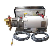
Waterous AQUIS 3.0 Installation, Operation And Maintenance Instructions (64 pages)
Brand:
Waterous
| Category:
Water Pump
| Size: 28.79 MB
Table of Contents
Table of Contents
2
Safety
4
Safety Precautions
4
Safety Precautions-Continued
5
Introduction
7
Using this Document
7
Viewing the Document Electronically
7
Printing the Document
7
Locating the Serial Number
7
Product Overview
7
Standard Components
8
Optional Components
9
AQUIS 1.5 Components
10
AQUIS 3.0 Components
12
AQUIS 1.5 and 3.0-Under the Cover
14
AQUIS 6.0 Components
16
AQUIS 6.0-Under the Cover
18
Overview Diagram-Typical
20
System Overview
21
Dual Tank System Overview-Optional
22
Dual Tank System Overview-Optional
23
Flush System Overview-Optional
24
Flush Kit Overview-Optional
25
Component Overview
26
Hose Lines and Fittings
26
Supply Hose
26
Inject Hose
26
Fittings
26
Bypass Hose
26
Pump Mounting Hardware
26
Power Cables
26
Concentrate Tank
26
OIT/HMI Cable
26
USB Port
27
Supply Tank Level Sensor
27
Supply Tank Level Sensor Cable
27
Supply Tank Shutoff Valve
27
Wye Fitting with Strainer
27
Concentrate Inject Check Valve
28
Flowmeter
28
Inject/Bypass Valve
28
Flowmeter Tee
29
Master Waterway Check Valve
30
Concentrate Injector
30
Drain Port
30
Foam Manifold
31
Concentrate Injector
31
Drain Port
31
Pressure Regulator Valve
32
Operator Interface Terminal (OIT)
33
Digital OIT
33
Manual OIT
33
Accessory Terminal Strip
34
Installation
35
Installation Precautions
35
Disconnecting the Frame Ground
35
Modifying the Foam System
35
Preparing for the Install
36
Installing the Vented Oil Cap
36
Determining the Pump Assembly Location
37
Locating the Pump Assembly Mounting Holes
37
Locating the OIT Mounting Holes
37
Installing the Pump Assembly
37
Installing the OIT
38
Connecting M12 Cables to the Control Box
38
Installing the Master Waterway Check Valve
39
Installing the Foam Manifold
39
Installing the Flowmeter Tee
40
Installing the Supply Hose
41
Installing the Injector Hose
41
Connecting the Bypass Hose
41
Fittings
41
Removing the Cover
41
Connecting the Power Supply
42
Installing the Tank Level-Sensor Cable
44
Installing the Wye Fitting with Strainer
44
Installing the Concentrate Inject Check Valve
45
Installing the Cover
45
Installing the Drain Lines
45
Calibrating-Manual OIT
46
Calibrating and Setup-Digital OIT
46
Entering the Calibration/Setup Mode
46
Editing the Default MIX Percentage-F1
47
Editing the Units of Measure-F2
47
Calibrating the Flow Rate-F3
48
Enabling System Lockout-F4
48
Selecting the Concentrate Source-F5
49
Simulating Water Flow-F6
49
Setting Default MIX Percent for B Foam-F7
50
Auto Run Mode
50
Operation
51
Operating Precautions
51
Hot Liquid
51
Hot Surface
51
Operating the Manual OIT
52
Operating in Normal Mode
52
Starting and Stopping the Pump
52
Adjusting the MIX Ratio
52
Operating in Manual Mode
53
Understanding the LED Indicators
53
Operating the Digital OIT
54
Powering up the OIT
55
Understanding the on LED
55
Operating in Normal Mode
55
Starting and Stopping the Pump
55
Adjusting the MIX Percentage
55
Operating in Manual Mode
55
Enabling Manual Mode
55
Operating and Disabling Manual Mode
56
Auto Run Mode-If Equipped
56
Changing the Display Mode
56
Displaying Default MIX Percent
56
Zeroing the Total Water Value
56
Zeroing the Total Foam Value
56
Displaying the Supply Tank
56
Operating the Inject/Bypass Valve
57
Draining the Foam System
57
Flushing the Foam System
57
Flushing the AQUIS Foam System
57
Maintenance Schedule
58
Servicing the Oil
58
Checking the Oil Level
58
Draining the Oil
58
Adding Oil
59
Completing the Oil Change
59
Replacing a Fuse
60
Tripping and Resetting the Circuit Breaker
60
Cleaning the Wye Fitting with Strainer
61
Inspecting the Hoses and Fittings
61
Inspect the Mounting Hardware
61
Troubleshooting
62
Trouble Shooting Chart
62
Advertisement
Related Products
Waterous AQUIS Series
Waterous AQUIS 1.5
Waterous AQUIS 6.0
Waterous Aquis 2.5 SSP
Waterous AQUIS ULTRAFLOW
Waterous 100-B
Waterous 100-D
Waterous 1000-150-P
Waterous 1000-150-PC
Waterous 1000-150-T
Waterous Categories
Water Pump
Firefighting Equipment
Industrial Equipment
Air Compressor
Control Unit
More Waterous Manuals
Login
Sign In
OR
Sign in with Facebook
Sign in with Google
Upload manual
Upload from disk
Upload from URL