Table of Contents
Advertisement
Quick Links
Read through the safety information
and overhaul instructions carefully
before repairing your Waterous TC20
Power Take-Off.
NOTE: Instructions subject to change without notice
Waterous Company, 125 Hardman Avenue South, South St. Paul, Minnesota 55075 USA (651) 450-5000
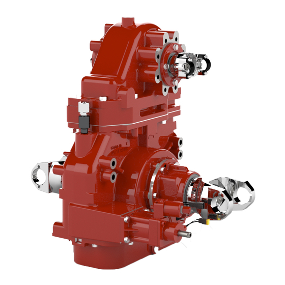
TC20 Chain Driven Power Take-Off
Section
Introduction
Ordering Repair Parts
General Information
Special Tools
Disassembly
Reassembly
www.waterousco.com
Overhaul Instructions
Table of Contents
Page
See Page 2
See Page 3
T-365 (Revised: 9/24/20)
4
4
5
6
Advertisement
Table of Contents

Related Manuals for Waterous TC20


Summary of Contents for Waterous TC20
- Page 1 Read through the safety information and overhaul instructions carefully before repairing your Waterous TC20 Power Take-Off. NOTE: Instructions subject to change without notice T-365 (Revised: 9/24/20) Waterous Company, 125 Hardman Avenue South, South St. Paul, Minnesota 55075 USA (651) 450-5000 www.waterousco.com...
-
Page 2: Table Of Contents
Table Of Contents Disassembly Drain Fluid from Transmission ....Removal of Driveline from Case: Removal of Output Shaft ....End Yokes or Companion Flanges . - Page 3 ....TC20 PTO .......
- Page 4 Refer to TC20 Series PTO Service Parts List furnished with your PTO for identification of individual components. When ordering repair parts, furnish the reference number of the compon ent (from Service Parts List) along with the PTO Model serial number. Gasket and O-ring repair kit (Part No. K-1117) is available from Waterous that includes all the gaskets and O-rings required for a complete overhaul.
- Page 5 Installing Ball Bearings Most Waterous PTOs are designed so that ball bearings fit tightly on their shafts and have relatively loose fits in the bearing housings. When mounting these bearings on shafts, always apply force to the inner races. When bear...
- Page 6 Drive (Input) Shaft Removal Sleeve Reference Page 18. Waterous Part No. 63431 Bracket is not available from Waterous and must be fabricated. Material: 4 in. Schedule 40 PVC Pipe NOTE: Provisions must be made to secure bracket to jack. Fasteners used must not interfere with case mounting.
- Page 7 (Reference Waterous Part No. V 3743) Reference pages 48-52 and 54-56. This sleeve is used when installing the Driveline in the PTO case. This sleeve is available from Waterous or may be fabricated per the diagrams below. Pipe Nipple Transmission Case Support Bracket (Reference Waterous Part No.
- Page 8 Waterous Part No.'s V 3722 and 63596 This tool is available from Waterous or may be fabricated per the diagram be low. Material: 1.250 Diameter Mild Steel Bar Stock...
-
Page 9: Drain Fluid From Transmission
Disassembly Drain Fluid from PTO Disconnect Propeller Shaft (Driveline) Driveline Input Driveline Output (Not required if PTO is configured with an input shaft only.) Disconnect propeller shaft (driveline) at the PTO input and output shafts and the PTO output shaft. NOTE: Driveline is furnished and installed by the truck builder, therefore configuration may vary from what is shown in the diagram. -
Page 10: Disconnect Output Shaft
Disassembly - Disconnect Output Shaft End Yoke Output Hydraulic Pump or Rear or Front Output Disconnect hydraulic pump from PTO. Remove two (2) 1/2-13 screws and lockwashers. Slide hy draulic pump away from PTO to dis engage splines on shafts. Disconnect Output Shaft NOTE: Hydraulic Pump is furnished... -
Page 11: Disconnect Optional Accessories: Tachometer Cable
Disassembly - Disconnect Optional Accessories Tachometer and Drain Valve Priming Pump (if equipped) - Disconnect Wiring and Hoses Tachometer (if equipped): Wiring to Priming Valve Disconnect Tachometer Cable. Unscrew cable from pick-up sensor on case. Hose to Priming Remove pick-up Valve sensor. -
Page 12: Shift Unit
Disassembly - Disconnect Optional Accessories Shift Unit Oil Temperature Sensor T-365 Page 12 of 75... -
Page 13: Eclipse™ Es Cafs On Rear Output
Disassembly - Disconnect Optional Accessories Eclipse™ ES CAFS on Rear Output Draining Compressor and Oil Cooler WARNING Electrical Hazard. Possible electrical shock. Disconnect electrical power to Eclipset ES unit (wire connected to Terminal No. 1 on Electrical Relay Panel (see Page 15) to prevent possible electrical shock. 1. -
Page 14: Removal Of Air Filter, Hoses And Cables
Disassembly - Disconnect Optional Accessories Eclipse™ ES CAFS on Rear Output (Continued) Removal of Air Filter, Hoses and Cables 2. Remove air filter to ease removal of pump from vehicle. Cable to Auto-Sync Panel 3. Disconnect hose 3a through 3e from unit. NOTE: Label hoses to ease reassembly. -
Page 15: Disconnect Wiring
Disassembly - Disconnect Optional Accessories Eclipse™ ES CAFS on Rear Output (Continued) Disconnect Wiring 5. Disconnect wiring from Terminals 1 through 8 along with ground wire from electrical relay panel. NOTE: Label wires to ease reassembly. Compressor Oil Sump 6. Disconnect wires from Oil Temperature Switch located on (Mounted remotely from pump on the vehicle. -
Page 16: Remove Pto From Vehicle
Disassembly - Remove PTO from Vehicle Removing PTO from Vehicle (8) Holes (2) Holes (both sides) 1. Remove drain plug from case. 2. Place a PTO jack with PTO case support bracket attached (see Page 6 for construction details) under the PTO. 3. -
Page 17: Remove Eclipse™ Es Unit From Pto
Disassembly - Remove Eclipset Unit from PTO Remove Eclipset ES CAFS Unit from PTO Eye Bolt Idler Sprocket Ad Clutch Key justment Screw Idler Pulley Five (5) 3/8-16 x 1 in. Screws and Lockwashers Two (2) M16 x 30mm Set Screw Screws and Lockwashers Air Clutch Eclipse ES™... -
Page 18: End Yokes Or Companion Flanges
3. If a new O-ring is required, note that the housing. a new O-ring is included in gasket kit Waterous Part No. K1117. 2. Discard lock nuts as they are not to be re-used. Note that new lock nuts are included in gasket kit Waterous Part No. -
Page 19: Shift Unit
Shift collar to PUMP (PTO) position. Remove 3/4 in. shoulder screw and discard. Screw is self-locking and is not to be re-used. Note that a new should screw is included in gasket kit Waterous Part No. K1117. T-365 Page 19 of 75... - Page 20 Disassembly - Removal of Driveline from Case (Continued) Shift Fork - Step 2 Shift Fork - Step 3 Step 2 Push slotted end of shift fork towards sprocket to clear mounting bracket. Step 3 Rotate fork and pull down to remove fork from case. T-365 Page 20 of 75...
-
Page 21: Removal Of Coupling (Output) Shaft
Disassembly - Removal of Driveline from Case (Continued) Removal of Coupling (Output) Shaft To remove coupling shaft from output side of case: Remove six (6) 3/8-16 x 1 in. screws and lockwashers. Install 3/8-16 x 1 in. screws in jacking screw holes and tighten to disengage coupling shaft housing from case. -
Page 22: Removal Of Drive (Input) Shaft
Disassembly - Removal of Driveline from Case (Continued) Removal of Drive (Input) Shaft Shift Collar Retaining Ring (Input Shaft Only Configurations) Retaining Ring Shift Collar Remove retaining ring loc ated behind shift collar. Leave shift collar in case. T-365 Page 22 of 75... -
Page 23: Pressing Out Drive Shaft
Place case on a suitable press as shown with drive shaft removal Apply force to the drive (input) shaft in the direction shown to dis sleeve (Waterous Part No. 63431, see Page 6) installed under the engage shaft from case. -
Page 24: Removing Drive Shaft, Sprocket And Housing
Disassembly - Removal of Driveline from Case (Continued) Removal of Drive (Input) Shaft Removing Drive Shaft, Sprocket and Housing Step 3 Remove case from the press and remove components as shown. Remove driveshaft housing. Note that the tachometer ring will be loose. -
Page 25: Drive (Input) Shaft
Disassembly - Driveline Components Drive (Input) Shaft Shaft Housing 1. Remove O-ring. 2. Remove oil seal. 3. Remove bearing. Transmission Case Support Bracket Remove bearing from shaft Sprocket Shift Fork Shoes 1. Remove both needle bearings 1. Remove shift shoes from fork. from sprocket bore. -
Page 26: Coupling (Output) Shaft
Disassembly - Driveline Components (Continued) Coupling (Output) Shaft Input Shaft Only Configurations Input and Output Shaft Configurations (No Coupling Shaft, Housing Only) 1. Press shaft out of housing. 1. Remove O-ring from housing. 2. Remove oil seal from housing. 2. Remove wave spring from housing. 3. -
Page 27: Removal Of Output Shaft
Disassembly - Removal of Output Shaft Removal of Output Shaft Various Output Connections are available on TC20 Series PTO's. The disassembly and reassembly of each varies slightly, use the diagram below to determine the output connection on your PTO. See Page... -
Page 28: Remove Cap From Case
Disassembly - Removal of Output Shaft Remove Cap from Case TC20B Models TC20C Models TC20D, TC20E and TC20F Models Note: The two (2) slots in the case flange may be used to help separate the cap from the case. T-365 Page 28 of 75... -
Page 29: End Yoke On Front Of Pto
Disassembly - Disassemble Cap End Yoke on Front of PTO Bearing Cover Four (4) 3/8-16 x 1 in. Screws and Lockwashers Rear Cap Flange Bearing Locknut O-ring Wave Spring Bearing Lockwasher Bearing Spacer Rear Cap Flange Narrow Spacer Front Cap Flange (Pump Side) Driven Sprocket Front Cap Flange... -
Page 30: End Yoke On Rear Of Pto
Disassembly - Disassemble Cap (Continued) End Yoke on Rear of PTO Four (4) 3/8-16 x 1 in. Bearing Cover Screws and Lockwashers O-ring Front Bearing Locknut Bearing Lockwasher Wave Spring Bearing Spacer Front Cap Flange Rear Driven Sprocket Rear Cap Flange Driven Shaft 1. -
Page 31: Hydraulic Pump On Front Of Pto
Disassembly - Disassemble Cap (Continued) Hydraulic Pump on Front of PTO Four (4) 3/8-16 x 1 in. Screws and Lockwashers Rear Bearing Cover O-ring Bearing Locknut Bearing Lockwasher Wave Spring Bearing Spacer Rear Cap Flange Front Driven Sprocket Front Cap Flange 1. -
Page 32: Hydraulic Pump On Rear Of Pto
Disassembly - Disassemble Cap (Continued) Hydraulic Pump on Rear of PTO Four (4) 3/8-16 x 1 in. Front Screws and Lockwashers Bearing Cover O-ring Bearing Locknut Bearing Lockwasher Wave Spring Bearing Spacer Front Cap Flange Rear Driven Sprocket Rear Cap Flange 1. -
Page 33: Eclipse™ Es Cafs On Rear Of Pto
Disassembly - Disassemble Cap (Continued) Eclipse ES™ CAFS on Rear of PTO Front Four (4) 3/8-16 x 1 in. Screws and Lockwashers Bearing Cover O-ring Bearing Locknut Bearing Lockwasher Wave Spring Single Row Bearing Bearing Lock nut Spacer Front Cap Flange Driven Sprocket Retaining Ring Rear Cap Flange... -
Page 34: End Yoke On Front And Hydraulic Pump On Rear
Disassembly - Disassemble Cap (Continued) End Yoke on Front and Hydraulic Pump on Rear Rear Four (4) 3/8-16 x 1 in. Hydraulic Pump Screws and Lockwashers Adapter O-ring Wave Spring Retaining Ring Spacer Bearing Rear Cap Flange Front Driven Sprocket Front Cap Flange Driven Shaft 1. -
Page 35: Hydraulic Pump On Front And End Yoke On Rear
Disassembly - Disassemble Cap (Continued) Hydraulic Pump on Front and End Yoke on Rear Oil Seal Four (4) 3/8-16 x 1 in. Front Screws and Lockwashers Hydraulic Pump O-ring Adapter Wave Spring Retaining Ring Spacer Bearing Front Cap Flange Rear Driven Sprocket Rear Cap Flange Driven Shaft... -
Page 36: Inspection And Repair
1. Before reassembly, make sure all reusable parts have been cleaned and kept free of dirt during reassembly. 2. All O-rings, gaskets, bearings, oil seals, etc. required for overhaul of the PTO are available in gasket kit Waterous Part No. K-1117. Ball Bearings and Oil Seals, O-rings Installing Ball Bearings Installing Oil Seals Keep new ball bearings wrapped until they are to be installed. -
Page 37: End Yoke On Front Of Pto
Reassembly - Assembly Cap End Yoke on Front of PTO Locknut, Torque to End Yoke Front 275-325 lb-ft. Four (4) 3/8-16 x 1 in. Oil Seal Screws and Lockwashers. Torque to 31 lb-ft Oil Seal Housing O-ring Bearing Rear Driven Shaft Use high pressure grease to coat the driven shaft's sprocket and bearing journals. -
Page 38: End Yoke On Rear Of Pto
Reassembly - Assembly Cap End Yoke on Rear of PTO Locknut, Torque to End Yoke 275-325 lb-ft. Rear Four (4) 3/8-16 x 1 in. Oil Seal Screws and Lockwashers. Torque to 31 lb-ft Oil Seal Housing O-ring Bearing Driven Shaft Front Use high pressure grease to coat the driven shaft's sprocket and bearing journals. -
Page 39: Hydraulic Pump On Front Of Pto
Reassembly - Assembly Cap Hydraulic Pump on Front of PTO Front Four (4) 3/8-16 x 1 in. Screws and Lockwashers. Oil Seal Torque to 31 lb-ft Hydraulic Pump Adapter O-ring Bearing Driven Shaft Rear Use high pressure grease to coat the driven shaft's sprocket and bearing journals. -
Page 40: Hydraulic Pump On Rear Of Pto
Reassembly - Assembly Cap Hydraulic Pump on Rear of PTO Rear Four (4) 3/8-16 x 1 in. Screws and Lockwashers. Oil Seal Torque to 31 lb-ft Hydraulic Pump Adapter O-ring Bearing Driven Shaft Front Use high pressure grease to coat the driven shaft's sprocket and bearing journals. -
Page 41: Eclipse™ Cafs Rear Of Pto
Reassembly - Assembly Cap Eclipse ES™ CAFS on Rear of PTO Spacer Four (4) 3/8-16 x 1 in. Oil Seal Screws and Lockwashers. Torque to 31 lb-ft Oil Seal Housing Shim, .010 in. Rear Driven Shaft Ball Bearing (Double Row) Front Retaining Ring Rear Cap Flange... -
Page 42: End Yoke On Front And Hydraulic Pump On Rear
Reassembly - Assembly Cap End Yoke on Front and Hydraulic Pump on Rear Locknut End Yoke Front Four (4) 3/8-16 x 1 in. Oil Seal Screws and Lockwashers. Torque to 31 lb-ft O-ring Oil Seal Housing Bearing Driven Shaft Rear Use high pressure grease to coat the driven shaft's sprocket and bearing journals. -
Page 43: Hydraulic Pump On Front And End Yoke On Rear
Reassembly - Assembly Cap Hydraulic Pump on Front and End Yoke on Rear Locknut End Yoke Rear Four (4) 3/8-16 x 1 in. Oil Seal Screws and Lockwashers. Torque to 31 lb-ft O-ring Oil Seal Housing Bearing Driven Shaft Front Use high pressure grease to coat the driven shaft's sprocket and bearing journals. -
Page 44: Attach Cap To Case: Apply Sealant To Flanges (All Pto Models)
Reassembly - Attach Cap to Case Apply Sealant T-365 Page 44 of 75... -
Page 45: Tc20F Models
Reassembly - Attach Cap to Case (Continued) TC20B Models TC20C Models TC20D, TC20E and TC20F Models Install ten (10) 1/2-13 screws (refer to service parts list for size Install ten (10) 1/2-13 screws (refer to service parts list for size and installation for each PTO model - varies by model and and installation for each PTO model - varies by model and ratio). -
Page 46: Drive Sprocket
Reassembly - Assemble Driveline Components Drive Sprocket Drive Shaft 1. Install one needle bearing in each end of the drive sprocket. 2. Install needle bearing (larger radius edge first) just below bot tom of chamfer on sprocket bore. Install bearing on shaft. -
Page 47: Coupling Shaft
Reassembly - Assemble Driveline Components (Continued) Coupling Shaft Input Shaft Only Configurations Input and Output Shaft Configurations - Step 1 (No Coupling Shaft, Housing Only) Sub-Assembly Shaft Install 4-3/4 x 5 in. O-ring Bearing Housing on bearing housing. Coat with grease. Install bearings and spacer on coupling shaft. -
Page 48: Drive (Input) Shaft
Install tachometer ring in counterbore of drive shaft installation sleeve. Grease O-ring Drive Shaft Installation Sleeve, Waterous Part No. 63432, See Page 7. Install drive shaft housing assembly on case with six (6) 3/8-16 x 1 in. screws and lockwashers. Torque to 31 lb-ft. -
Page 49: Install Case On Installation Tool
Reassembly - Installation of Driveline in Case (Continued) Drive (Input) Shaft Install Case on Installation Tool 4. Place drive shaft installation sleeve on an arbor press. 5. Place case on drive shaft installation sleeve. Use ap propriate blocking to level the case. Case with drive NOTE: Alignment is done with drive shaft housing shaft housing... -
Page 50: Install Drive Sprocket
Reassembly - Installation of Driveline in Case (Continued) Drive (Input) Shaft Install Drive Sprocket Install thrust washer in case cen tering bore with bearing. Install drive sprocket in case cen tering bore with thrust washer. T-365 Page 50 of 75... -
Page 51: Install Drive Shaft In Case
Reassembly - Installation of Driveline in Case (Continued) Drive (Input) Shaft Install Drive Shaft in Case Press drive shaft assembly into case and through sprocket and drive shaft housing. T-365 Page 51 of 75... -
Page 52: Shift Collar
Reassembly - Installation of Driveline in Case (Continued) Shift Collar Input and Output Shaft Configuration Input Shaft Only Configuration Install shift collar on drive shaft, slide over spline teeth on both drive shaft and sprocket. Install shift collar on drive shaft, Install retaining ring in groove on slide over spline teeth on both drive shaft spline behind shift... -
Page 53: Chain
Reassembly - Installation of Driveline in Case (Continued) Chain 1. Wrap the chain around the drive and driven sprockets making sure everything meshes and then lace the joining ends together using the connecting pin set. NOTE: Move collar to PUMP position. Retain drive shaft / sprocket to prevent rotation. -
Page 54: Coupling (Output) Shaft
Reassembly - Installation of Driveline in Case (Continued) Coupling (Output) Shaft Input and Output Shaft Configuration (Wave Spring Design Prior to March 12, 2013) 10. Grease O-ring on coupling shaft housing. 11. Press coupling shaft housing assembly on drive shaft bearing. 12. -
Page 55: Shim Design After March 12, 2013
Reassembly - Installation of Driveline in Case (Continued) Coupling (Output) Shaft Input and Output Shaft Configuration (Shimming Design After March 12, 2013) Six (6) 3/8-16 x 1 in. Screws and Lockwashers. Torque to 31 lb-ft. The driveline assembly was factory shimmed to limit the axial float of the driveline. -
Page 56: Input Shaft Only Configurations
Reassembly - Installation of Driveline in Case (Continued) Coupling (Output) Shaft Input Only Shaft Configuration 10. Grease O-ring on bearing housing. 11. Press bearing housing on drive shaft bearing. 12. Install six (6) 3/8-16 x 1 in. screws and lockwashers. Torque to 31 lb-ft. Six (6) 3/8-16 x 1 in. -
Page 57: Oil Seals
Reassembly - Installation of Driveline in Case (Continued) Oil Seals and Tachometer Sensor Coupling Shaft Tachometer Sensor: If PTO is equipped with an option al tachometer, install sensor in drive shaft housing as follows: Install O-ring in housing, apply grease. Thread sensor into hous... -
Page 58: Shift Fork
Reassembly - Installation of Driveline in Case (Continued) Shift Fork Step 1 Step 2 Sprocket Step 1 Step 2 Place collar in PTO position. Slide shift fork onto shift collar in case. Pull arm of shift fork away from sprocket aligning hole in (Ensure shift shoes are installed, see fork with hole in case ears. -
Page 59: Shift Unit
Reassembly - Installation of Driveline in Case (Continued) Shift Fork / Shift Unit Step 3 Shift Unit 1. Install a new 1-13/16 x 2 in. O-ring on shift unit. Coat O-ring with grease. 2. Place shift unit in ROAD Mode by pushing override rod in. 3. -
Page 60: Oil Pan
Reassembly - Installation of Driveline in Case (Continued) Oil Pan End Yokes or Companion Flanges 1. Install gasket on oil pan. 1. Lubricate oil seal in housing. 2. Attach oil pan to case with twelve (12) 3/8-16 x 1 in. screws and 2. -
Page 61: Input And Output Shaft Configurations
Reassembly - Installation of Driveline in Case (Continued) Cross-Section Diagram of Driveline Input and Output Shaft Configurations T-365 Page 61 of 75... -
Page 62: Input Shaft Only Configurations
Reassembly - Installation of Driveline in Case (Continued) Cross-Section Diagram of Driveline Input Shaft Only Configuration WITHOUT TACHOMETER WITH OPTIONAL TACHOMETER INPUT END T-365 Page 62 of 75... -
Page 63: Eclipse™ Es Unit On Pto
Reassembly - Installation of Eclipse™ ES Unit Eclipset ES Unit on PTO Dimple in Shaft for Air Clutch Set Screw Screws Lifting Eye Bolts See the Next Page Screws Set Screw Air Clutch Eclipse ES™ Unit Belt Anti-Rotation Bracket Air Line End Yoke Attach a hoist to the Eclipse ES unit. -
Page 64: Adjusting Belt Tension
Reassembly - Installation of Eclipse™ ES Unit (Continued) Adjusting Belt Tension Adjust belt tension as follows: a. Loosen the idler sprocket by turning the large hex screw counterclockwise. b. Turn the idler sprocket adjustment screw clockwise to apply tension to the belt. Check the belt tension by applying a 10 pound load to the belt midway between the drive and driven sprocket. -
Page 65: Installation Of Pto In Vehicle
Reassembly - Installation of PTO in Vehicle Installation of PTO in Vehicle 1. Secure PTO to support bracket on PTO jack. 2. Raise PTO up into vehicle. 3. Connect PTO to original mounting brackets in vehicle. NOTE: Ensure pump and PTO are within 1/8” before installing hardware. 4. -
Page 66: Connection Of Propeller Shaft (Driveline)
Reassembly - Installation of PTO in Vehicle (Continued) Connection of Propeller Shaft (Driveline) NOTE: Output shaft is not used for in put shaft only PTO configurations. Connect vehicle propeller shafts to PTO. T-365 Page 66 of 75... -
Page 67: Connection Of Optional Accessories
Reassembly - Installation of PTO in Vehicle (Continued) Connection of Optional Accessories Hydraulic Pump on Rear or Front Output End Yoke on Front or Rear Output Install hydraulic pump on PTO using two (2) 1/2-13 screws and lockwashers. Torque to 75 lb-ft Connect Shaft to PTO Output... -
Page 68: Tachometer Cable
Reassembly - Installation of PTO in Vehicle (Continued) Connection of Optional Accessories Tachometer Cable and Drain Valve Priming Pump - Mounting on Transmission Step 1 Install priming pump on transmission with four (4) 3/8-16 x 1 in. screws and lockwashers. Torque to 31 lb-ft. -
Page 69: Wiring Connections
Reassembly - Installation of PTO in Vehicle (Continued) Connection of Optional Accessories Priming Pump - Wiring Connections T-365 Page 69 of 75... -
Page 70: Shift Unit
Reassembly - Installation of PTO in Vehicle (Continued) Connection of Optional Accessories Shift Unit Oil Temperature Sensor T-365 Page 70 of 75... -
Page 71: Eclipse™ Es Cafs On Rear Output: Hoses And Air Filter
Reassembly - Installation of PTO in Vehicle (Continued) Connection of Optional Accessories Eclipset ES CAFS on Rear Output - Hoses and Cables 1. Install air filter. 2. Connect cable to Auto-Sync Panel. 3. Connect hoses 3a through 3e. Cable to Auto-Sync Panel 4. -
Page 72: Electrical Wiring
Reassembly - Installation of PTO in Vehicle (Continued) Connection of Optional Accessories Eclipset ES CAFS on Rear Output - Electric Wiring Compressor Oil Sump (Mounted remotely from pump on the vehicle.) Green Wire (Large Terminal) Oil Temperature Switch Electrical Relay Panel Yellow Wire (Small Terminal) Power... -
Page 73: Schematic
Reassembly - Installation of PTO in Vehicle (Continued) Connection of Optional Accessories Eclipset ES CAFS on Rear Output - Electric Wiring Continued Wiring Schematic T-365 Page 73 of 75... -
Page 74: Lubrication: Tc20 Pto
Reassembly - Lubrication Eclipset ES CAFS Unit TC20 Power Take-Off 1. Fill the PTO through the oil level hole or by removing the breather and 1. Fill the compressor sump with oil. Use ISO 68 viscosity oil. System adding fluid through the opening. Any type of automatic PTO fluid holds approximately 2 to 3 gallons. -
Page 75: Shift Indication Light Operation
Reassembly - Final Checks Eclipset ES CAFS Unit Shift Indication Light Operation Re-check for proper operation of shift mechanism and that the shift indic 1. Engage water pump and CAFS unit per appropriate operation instruc ator light system is functioning properly. tions.
Need help?
Do you have a question about the TC20 and is the answer not in the manual?
Questions and answers