Table of Contents
Advertisement
Form Number: F-1031
Issue Date: Aug 1, 2017
Section: 2447
Revision Date: Aug 22, 2019
AQUIS™ Foam System
Installation, Operation, and Maintenance Instructions
AQUIS 1.5, AQUIS 3.0, and AQUIS 6.0
Waterous Company • 125 Hardman Avenue South • South Saint Paul, MN 55075 • (651) 450-5000
www.waterousco.com
Advertisement
Table of Contents

Related Manuals for Waterous AQUIS Series


Summary of Contents for Waterous AQUIS Series
- Page 1 Issue Date: Aug 1, 2017 Section: 2447 Revision Date: Aug 22, 2019 AQUIS™ Foam System Installation, Operation, and Maintenance Instructions AQUIS 1.5, AQUIS 3.0, and AQUIS 6.0 Waterous Company • 125 Hardman Avenue South • South Saint Paul, MN 55075 • (651) 450-5000 www.waterousco.com...
-
Page 2: Table Of Contents
Table of Contents Master Waterway Check Valve Safety Concentrate Injector Safety Precautions Drain Port Safety Precautions—Continued Foam Manifold Introduction Concentrate Injector Drain Port Using this Document Pressure Regulator Valve Viewing the Document Electronically Operator Interface Terminal (OIT) Printing the Document Digital OIT Locating the Serial Number Manual OIT... - Page 3 Maintenance Removing the Cover Connecting the Power Supply Maintenance Schedule Installing the Tank Level—Sensor Cable Servicing the Oil Installing the Wye Fitting with Strainer Checking the Oil Level Installing the Concentrate Inject Check Valve Draining the Oil Installing the Cover Adding Oil Installing the Drain Lines Completing the Oil Change...
-
Page 4: Safety
Refer to instruction shipping plug and replace • Regularly check for leaks, worn, or deteriorated parts. F-1031-2447 for it with this vented oil cap. • Waterous reserves the right to make modifications to the system without detailed information. notice. NOTICE High Current High current from welding •... -
Page 5: Safety Precautions-Continued
Warranty Safety Introduction Product Overview Installation Operation Maintenance Troubleshooting Service Parts Safety Precautions—Continued NOTICE NOTICE Modification Equipment Damage Modifying the equipment • Using the wrong fuse may • can damage components damage the equipment. and void your warranty. Only use the specified fuse •... - Page 6 Warranty Safety Introduction Product Overview Installation Operation Maintenance Troubleshooting Service Parts Safety Precautions—Continued High Current High Pressure Current can cause serious Liquid ejected at high • • injury or death. pressure can cause serious injury. Disconnect the power • Drain the lines before before servicing the pump.
-
Page 7: Introduction
This document is divided into the following sections: Locate and record the model and serial number of the equipment in your Safety application. Have this information available when you call Waterous. This section describes general precautions and alert symbols that are in this document. -
Page 8: Product Overview
Warranty Safety Introduction Product Overview Installation Operation Maintenance Troubleshooting Service Parts Standard Components This table shows the standard components that are associated with the different AQUIS foam system configurations. Included Foam Only or Traditional CAFSystems™ ONE STEP™ and Eclipse GEN 2.0™ with AQUIS 1.5 AQUIS 3.0... -
Page 9: Optional Components
Warranty Safety Introduction Product Overview Installation Operation Maintenance Troubleshooting Service Parts Optional Components Available with: This table shows additional components that are available to meet the requirements of your application. ONE STEP Traditional CAFS Eclipse GEN 2.0 Component Purpose Foam Only CAFS Supply level sensor This sensor alerts you when the concentrate in the supply tank reaches a predetermined level. -
Page 10: Aquis 1.5 Components
Warranty Safety Introduction Product Overview Installation Operation Maintenance Troubleshooting Service Parts AQUIS 1.5 Components Figure 1... - Page 11 Warranty Safety Introduction Product Overview Installation Operation Maintenance Troubleshooting Service Parts AQUIS 1.5 Components Feature Description Oil level window This shows the oil level in the pump. Cover This covers the control box and terminal strip. Pump This is the pump assembly. Vented oil cap This is cap replaces the shipping cap.
-
Page 12: Aquis 3.0 Components
Warranty Safety Introduction Product Overview Installation Operation Maintenance Troubleshooting Service Parts AQUIS 3.0 Components Figure 2... - Page 13 Warranty Safety Introduction Product Overview Installation Operation Maintenance Troubleshooting Service Parts AQUIS 3.0 Components Feature Description Oil level window This shows the oil level in the pump. Cover This covers the control box and terminal strip. Vented oil cap This is cap replaces the shipping cap. Pump This is the pump assembly.
-
Page 14: Aquis 1.5 And 3.0-Under The Cover
Warranty Safety Introduction Product Overview Installation Operation Maintenance Troubleshooting Service Parts AQUIS 1.5 and 3.0—Under the Cover Figure 3... - Page 15 Warranty Safety Introduction Product Overview Installation Operation Maintenance Troubleshooting Service Parts AQUIS 1.5 and 3.0—Under the Cover Feature Description Accessory terminal strip This connects accessories to the control box. Circuit breaker This prevents over-current. Control box This houses the electric components. Flowmeter connection This connects control box to the flowmeter.
-
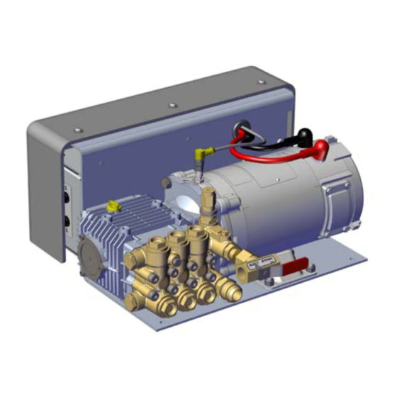
Page 16: Aquis 6.0 Components
Warranty Safety Introduction Product Overview Installation Operation Maintenance Troubleshooting Service Parts AQUIS 6.0 Components Figure 4... - Page 17 Warranty Safety Introduction Product Overview Installation Operation Maintenance Troubleshooting Service Parts AQUIS 6.0 Components Feature Description Oil level window This shows the oil level in the pump. Cover This covers the control box and terminal strip. Pump This is the pump assembly. Vented oil cap This is cap replaces the shipping cap.
-
Page 18: Aquis 6.0-Under The Cover
Warranty Safety Introduction Product Overview Installation Operation Maintenance Troubleshooting Service Parts AQUIS 6.0—Under the Cover Figure 5... - Page 19 Warranty Safety Introduction Product Overview Installation Operation Maintenance Troubleshooting Service Parts AQUIS 6.0—Under the Cover Feature Description Accessory terminal strip This connects accessories to the control box. Fuse housing This is the fuse location. Circuit breaker This prevents over-current. HMI/OIT connection This connects the controller to the HMI or OIT.
-
Page 20: Overview Diagram-Typical
Warranty Safety Introduction Product Overview Installation Operation Maintenance Troubleshooting Service Parts Overview Diagram—Typical Note: The graphics in this illustration are intended to help you understand concepts in next sections. Do not use them to determine physical attributes, placement or proportion. -
Page 21: System Overview
Service Parts System Overview The following information describes the components the are used in a typical foam system setup. Your application may not include all, or contain additional components than the ones described below. Contact Waterous for more information. Component/Accessory Description... -
Page 22: Dual Tank System Overview-Optional
Warranty Safety Introduction Product Overview Installation Operation Maintenance Troubleshooting Service Parts Dual Tank System Overview—Optional Note: The graphics in this illustration are intended to help you understand concepts in next sections. Do not use them to determine physical attributes, placement or proportion. -
Page 23: Dual Tank System Overview-Optional
Dual Tank System Overview—Optional In addition to the typical setup, you can add additional flexibility by incorporating the dual tank option. Below is a description of the additional components used in most applications. Contact Waterous for more information. Component/Accessory Description Dual tank controller This controller switches the source that supplies concentrate to the pump. -
Page 24: Flush System Overview-Optional
Warranty Safety Introduction Product Overview Installation Operation Maintenance Troubleshooting Service Parts Flush System Overview—Optional... -
Page 25: Flush Kit Overview-Optional
You can add the flush kit to the AQUIS to flush the system when necessary. The environment, the concentrate used, and other factors determine if or when you need to flush the foam pump. Refer to the apparatus and/or concentrate manufacturer to determine a protocol for flushing. Contact Waterous for more information. -
Page 26: Component Overview
Hose lines distribute the concentrate between the foam system components. This cable connects the flowmeter to the control box (Figure 3 Figure Hoses are not supplied in this kit. Contact Waterous for more information. This cable is an M12, 5-pin connector. Supply Hose Cable Extension Extension cables extend the routing distance of the flowmeter or OIT/HMI The supply hose routes the concentrate from the supply tank to pump. -
Page 27: Usb Port
Figure Supply Tank Level Sensor This sensor alerts you when the concentrate reaches a predetermined level in the supply tank. A sensor not supplied in this kit. Contact Waterous for information about obtaining a sensor. Figure 8 Wye Fitting with Strainer... -
Page 28: Concentrate Inject Check Valve
Warranty Safety Introduction Product Overview Installation Operation Maintenance Troubleshooting Service Parts Concentrate Inject Check Valve Inject/Bypass Valve This check valve is installed in the injector fitting and prevents the foam solution Use the inject/bypass valve (Figure 12) to manually direct the concentrate as from entering the concentrate hose (Figure 10). -
Page 29: Flowmeter Tee
Warranty Safety Introduction Product Overview Installation Operation Maintenance Troubleshooting Service Parts Flowmeter Tee The flowmeter tee houses the flowmeter and measures the amount of water flowing from the waterway supply line (Figure 13). 1. Flowmeter 2. Tee body Figure 13 The flowmeter tee is available in the following configurations: 2-inch tee Inlet/Outlet:... -
Page 30: Master Waterway Check Valve
Warranty Safety Introduction Product Overview Installation Operation Maintenance Troubleshooting Service Parts Master Waterway Check Valve Concentrate Injector This valve ensures that the water and concentrate flow in one direction (Figure 14). It prevents the mix flowing into the water tank or pump. The check This fitting injects the concentrate into the waterway to create the valve is available in the following configurations: solution in the apparatus... -
Page 31: Foam Manifold
3. Manifold 1. Drain Figure 16 Inlet/Outlet Figure 17 2-1/2 inches Waterous 4-bolt flange (4-3/8 B.C.) Combination: Victaulic (2 inches) and FNPT (1-1/2 inches) Combination: Victaulic (2-1/2 inches) and FNPT (2 inches) Combination: Victaulic (3 inches) and FNPT (2-1/2 inches) -
Page 32: Pressure Regulator Valve
Warranty Safety Introduction Product Overview Installation Operation Maintenance Troubleshooting Service Parts Pressure Regulator Valve This valve is set at the factory to bypass at 450 psi (31 bar). When the pressure reaches 450 psi (31 bar), the valve opens and the concentrate is routed from the output side of the pump to the input side of the pump. -
Page 33: Operator Interface Terminal (Oit)
Warranty Safety Introduction Product Overview Installation Operation Maintenance Troubleshooting Service Parts Operator Interface Terminal (OIT) Manual OIT The OIT enables or disables the foam system operation and adjusts the amount The manual OIT (Figure 22) communicates with the pump controller to of concentrate that is injected into the waterway. -
Page 34: Accessory Terminal Strip
Warranty Safety Introduction Product Overview Installation Operation Maintenance Troubleshooting Service Parts Accessory Terminal Strip The terminal strip adds accessories and functionality to the pump. The terminal strip (Figure 24) is located under the cover on the controller (Figure 23). Figure 23 Figure 24 Description Comments... -
Page 35: Installation
The foam system is intended to be installed by a person or persons with The foam system components are designed to operate mounted to the basic knowledge of installing similar equipment. Contact Waterous with the mounting bracket. Removing the components from the mounting questions about installing the foam system. -
Page 36: Dimensions-Aquis 1.5
Warranty Safety Introduction Product Overview Installation Operation Maintenance Troubleshooting Service Parts Dimensions—AQUIS 1.5 INJECT/BYPASS VALVE Inject/Bypass Valve OIL FILL Oil Fill 1.373in 34.88mm 16.356in 415.45mm 2.626in 66.71mm 15.589in 1/2 FNPT Foam 1/2 FNPT FOAM #12 MJIC Foam Supply In 395.95mm #12 MJIC FOAM SUPPLY IN INJECTION OUT Injection Out... - Page 37 Warranty Safety Introduction Product Overview Installation Operation Maintenance Troubleshooting Service Parts Dimensions—AQUIS 3.0 #12 MJIC FOAM SUPPLY IN #12 MJIC Foam Supply In INJECT/BYPASS VALVE Inject/Bypass Valve 2X 13.500in 3.234in 342.90mm 82.13mm OIL FILL / DIPSTICK Oil Fill/Dipstick 10.990in 5.155in 279.15mm 130.94mm 10.872in...
-
Page 38: Dimensions-Aquis 6.0
Warranty Safety Introduction Product Overview Installation Operation Maintenance Troubleshooting Service Parts Dimensions—AQUIS 6.0 INJECT/BYPASS VALVE Inject/Bypass Valve Oil Fill/Dipstick OIL FILL / DIPSTICK 1 FNPT Foam Supply In 1 FNPT FOAM SUPPLY IN 13.927in 1/2 FNPT Foam 1/2 FNPT FOAM 353.74mm INJECTION OUT Injection Out... -
Page 39: Dimensions-Digital Oit
Warranty Safety Introduction Product Overview Installation Operation Maintenance Troubleshooting Service Parts Dimensions—Digital OIT Panel Cutout Use the self-tapping screws included to secure the OIT to the panel. Figure 28... -
Page 40: Dimensions-Digital Oit Instruction Plate
Warranty Safety Introduction Product Overview Installation Operation Maintenance Troubleshooting Service Parts Dimensions—Digital OIT Instruction Plate Panel Hole Cutout Figure 29... -
Page 41: Dimensions-Manual Oit
Warranty Safety Introduction Product Overview Installation Operation Maintenance Troubleshooting Service Parts Dimensions—Manual OIT Panel Hole Cutout Figure 30... -
Page 42: Dimensions-Foam Tee
Warranty Safety Introduction Product Overview Installation Operation Maintenance Troubleshooting Service Parts Dimensions—Foam Tee Figure 31... -
Page 43: Dimensions-Foam Manifold
Warranty Safety Introduction Product Overview Installation Operation Maintenance Troubleshooting Service Parts Dimensions—Foam Manifold 5.000in 127mm 3.094in 3.094in 78.58mm 78.58mm 1.547in 1.547in Includes Flowmeter 39.29mm 39.29mm 4.375in 111.13mm .469in 4.250in 4.375in 11.91mm 107.95mm 12.000in 4.250in 111.13mm 304.80mm 107.95mm 4X 7/16-14 UNC 1.000 5.000in 127mm... -
Page 44: Dimensions-2-1/2 Inch Check Valve Victaulic X Fnpt
Warranty Safety Introduction Product Overview Installation Operation Maintenance Troubleshooting Service Parts Dimensions—2-1/2 Inch Check Valve Victaulic x FNPT 163.83mm 15.88mm 7.92mm 213.82mm 48.27mm 96.54mm Figure 33... -
Page 45: Dimensions-2-1/2 Inch Check Valve Victaulic X Victaulic
Warranty Safety Introduction Product Overview Installation Operation Maintenance Troubleshooting Service Parts Dimensions—2-1/2 Inch Check Valve Victaulic x Victaulic 158.75mm 7.92mm 7.92mm 15.88mm 15.88mm 208.74mm 48.27mm 96.54mm Figure 34... -
Page 46: Dimensions-2 Inch Check Valve Victaulic X Fnpt
Warranty Safety Introduction Product Overview Installation Operation Maintenance Troubleshooting Service Parts Dimensions—2 Inch Check Valve Victaulic x FNPT 147.62mm 197.62mm 15.88mm 40.41mm 7.95mm 80.82mm Figure 35... -
Page 47: Dimensions-2 Inch Check Valve Victaulic X Victaulic
Warranty Safety Introduction Product Overview Installation Operation Maintenance Troubleshooting Service Parts Dimensions—2 Inch Check Valve Victaulic x Victaulic 147.62mm 15.88mm 7.95mm 197.62mm 40.41mm 15.88mm 80.82mm 7.95mm Figure 36... -
Page 48: Dimensions-1-1/2 Inch Check Valve Victaulic/Fnpt X Fnpt
Warranty Safety Introduction Product Overview Installation Operation Maintenance Troubleshooting Service Parts Dimensions—1-1/2 Inch Check Valve Victaulic/FNPT x FNPT Figure 37... -
Page 49: Dimensions-1-1/2 Inch Check Valve Victaulic/Fnpt X Victaulic
Warranty Safety Introduction Product Overview Installation Operation Maintenance Troubleshooting Service Parts Dimensions—1-1/2 Inch Check Valve Victaulic/FNPT x Victaulic Figure 38... -
Page 50: Preparing For The Install
Warranty Safety Introduction Product Overview Installation Operation Maintenance Troubleshooting Service Parts Preparing for the Install Installing the Vented Oil Cap Consider the information below before you begin installing the foam system. NOTICE • Determine the install location for the components, consider wire and hose routing, mounting locations and maintenance requirements. -
Page 51: Determining The Pump Assembly Location
Warranty Safety Introduction Product Overview Installation Operation Maintenance Troubleshooting Service Parts Determining the Pump Assembly Location Installing the Pump Assembly Use the following guidelines to determine a location to mount the pump The foam system components are designed to operate as installed on the assembly: mounting bracket (Figure... -
Page 52: Installing The Oit
Warranty Safety Introduction Product Overview Installation Operation Maintenance Troubleshooting Service Parts Installing the OIT Connecting M12 Cables to the Control Box 1. Locate one end of the M12, 8-pin cable. 1. Remove the cover. Refer to: "Removing the Cover" on page 2. -
Page 53: Installing The Master Waterway Check Valve
3. Use cable ties to secure the cable to the apparatus. Note: Do not secure the wire harness to hot or moving parts. Note: Waterous for information about obtaining a cable extension. 4. Install the cover. Refer to: "Installing the Cover" on page... -
Page 54: Installing The Flowmeter Tee
Warranty Safety Introduction Product Overview Installation Operation Maintenance Troubleshooting Service Parts Installing the Flowmeter Tee 2. Install the inlet side of the manifold towards the water pump. Important: Installing the foam manifold at more than a ± 15° tilt may 1. -
Page 55: Installing The Supply Hose
3. Use cable ties to secure the hoses to the apparatus. Note: Do not pinch or kink the hose. Note: Do not secure the hose to hot or moving parts. Note: An optional hose kit is available, contact your Waterous for more Figure 46 information. -
Page 56: Removing The Cover
Warranty Safety Introduction Product Overview Installation Operation Maintenance Troubleshooting Service Parts Removing the Cover Connecting the Power Supply 1. Remove the 3 screws and washers that are used to secure the cover to the frame and set them aside (Figure 47). - Page 57 Warranty Safety Introduction Product Overview Installation Operation Maintenance Troubleshooting Service Parts The electrical requirements vary based on your specific application. The 4. Connect the other end of the positive (+) cable to the positive (+) post of the following tables are calculated using the SAE J1128 standard with a 2% drop. foam pump (Figure 48).
-
Page 58: Installing The Tank Level-Sensor Cable
Warranty Safety Introduction Product Overview Installation Operation Maintenance Troubleshooting Service Parts Installing the Tank Level—Sensor Cable Installing the Wye Fitting with Strainer 1. Connect the sensor wires to the wires on the foam concentrate sensor. The wye fitting with strainer is installed in-line with the supply shutoff valve and the supply hose. -
Page 59: Installing The Concentrate Inject Check Valve
Warranty Safety Introduction Product Overview Installation Operation Maintenance Troubleshooting Service Parts Installing the Concentrate Inject Check Valve Installing the Drain Lines 1. Use the arrow on the check valve to determine the flow direction of the Install a dedicated line to the drain port on the check valve or manifold to concentrate (Figure 51). -
Page 60: Calibrating-Manual Oit
Warranty Safety Introduction Product Overview Installation Operation Maintenance Troubleshooting Service Parts Calibrating—Manual OIT Calibrating and Setup—Digital OIT Entering the Calibration/Setup Mode 1. Rotate the (FOAM % dial) to 0. 1. Press and hold the (SELECT button). 2. Press and hold the (ON/OFF button) for 6 seconds. -
Page 61: Editing The Default Mix Percentage-F1
Warranty Safety Introduction Product Overview Installation Operation Maintenance Troubleshooting Service Parts Editing the Default Mix Percentage—F1 Editing the Units of Measure—F2 1. Enter the calibration/setup mode. Refer to: 1. Enter the calibration/setup mode. Refer to: "Entering the Calibration/Setup Mode" on page 60. "Entering the Calibration/Setup Mode"... -
Page 62: Calibrating The Flow Rate-F3
(FOAM button) to save the value and exit the display value to match the value that you measured. calibration and setup mode. Note: Contact Waterous for more information about locking and • When the (low flow) value is displayed, an insufficient unlocking the OIT. -
Page 63: Selecting The Concentrate Source-F5
Warranty Safety Introduction Product Overview Installation Operation Maintenance Troubleshooting Service Parts Selecting the Concentrate Source—F5 calibration and setup mode. Simulating Water Flow—F6 1. Enter the calibration/setup mode. Refer to: "Entering the Calibration/Setup Mode" on page Use this mode to test and verify the foam system operation. This function is available for the AQUIS 1.5 with digital head, AQUIS 3.0 and 2. -
Page 64: Setting Default Mix Percent For B Foam-F7
Warranty Safety Introduction Product Overview Installation Operation Maintenance Troubleshooting Service Parts Setting Default Mix Percent for B Foam—F7 11. Use the following chart to determine your flow rate. Default mix percentage 1. Enter the calibration/setup mode. Refer to: "Entering the Calibration/Setup Mode" on page 0.1% 0.2% 0.3% 0.4% .05% 0.6% 0.7% 0.8% 0.9% 1.0% 2. -
Page 65: Operation
The foam system is intended to be operated by a person, or persons, with Components in the foam system may become hot during operation. the basic knowledge of operating similar equipment. Contact Waterous with questions about operating the foam system. Be aware of the following... -
Page 66: Operating The Manual Oit
Warranty Safety Introduction Product Overview Installation Operation Maintenance Troubleshooting Service Parts Operating the Manual OIT Operating in Normal Mode In normal operating mode, the OIT uses information from the flowmeter and the FOAM % dial to produce the desired mix. Starting and Stopping the Pump 1. -
Page 67: Operating In Manual Mode
Warranty Safety Introduction Product Overview Installation Operation Maintenance Troubleshooting Service Parts Operating in Manual Mode Understanding the LED Indicators The foam system can operate in manual mode as required by the NFPA Blue LED regulation. While in manual mode, the foam system injects concentrate into •... -
Page 68: Operating The Digital Oit
Warranty Safety Introduction Product Overview Installation Operation Maintenance Troubleshooting Service Parts Operating the Digital OIT 1 Mounting hardware The hardware mounts OIT to the apparatus. 2 FOAM button This button starts and stops the pump operation. 3 Display The display shows 4 characters that represent the value for the current mode. -
Page 69: Powering Up The Oit
Warranty Safety Introduction Product Overview Installation Operation Maintenance Troubleshooting Service Parts Powering Up the OIT Operating in Manual Mode The apparatus manufacturer determines how the foam system powers up in The foam system can operate in manual mode as required by the NFPA your application. -
Page 70: Operating And Disabling Manual Mode
Warranty Safety Introduction Product Overview Installation Operation Maintenance Troubleshooting Service Parts Operating and Disabling Manual Mode Displaying Default Mix Percent In manual mode you can start or stop the pump and increase or decrease the foam percent. 1. Press the (SELECT button) until the PERCENT LED illuminates. -
Page 71: Operating The Inject/Bypass Valve
Follow the instructions from the apparatus manufacturer to drain the valve. 1. Make the apparatus ready for flushing. Refer to the documentation Contact Waterous for more information. provided by the apparatus manufacturer for more information. 2. Enable manual mode on the OIT. Refer to: •... -
Page 72: Maintenance Schedule
Warranty Safety Introduction Product Overview Installation Operation Maintenance Troubleshooting Service Parts Maintenance Schedule Perform the following procedures at the recommended intervals. Every 8 Every 50 Every 500 Operation Hours Hours Hours Check the oil level High Pressure Inspect the hoses and fittings Clean the wye fitting with strainer Liquid ejected at high •... -
Page 73: Adding Oil
Warranty Safety Introduction Product Overview Installation Operation Maintenance Troubleshooting Service Parts Adding Oil 4. Loosen and remove the drain plug on the bottom of the pump (Figure 59). Note: Only use SAE 30, non-detergent oil. 1. Remove the vented oil cap and set it aside (Figure Figure 2,and... -
Page 74: Replacing A Fuse
Warranty Safety Introduction Product Overview Installation Operation Maintenance Troubleshooting Service Parts Replacing a Fuse Tripping and Resetting the Circuit Breaker 1. Remove the cover. Refer to: "Removing the Cover" on page Note: Only use a fuse with the following specifications: •... -
Page 75: Cleaning The Wye Fitting With Strainer
Warranty Safety Introduction Product Overview Installation Operation Maintenance Troubleshooting Service Parts Cleaning the Wye Fitting with Strainer Inspecting the Hoses and Fittings Clean the wye fitting every 50 hours of use. Check the hoses and fittings every 50 hours of use. 1. -
Page 76: Troubleshooting
• The system is operating in manual mode. • Press the up and down buttons simultaneously. • The foam system is out of calibration. • The controller requires reprogramming, contact Waterous. Insufficient concentrate is being • The flowmeter is out of calibration. - Page 77 • Verify that the pins on the cable are not bent, replace the bars. controller. cable if they are damaged. Contact Waterous to replace the control box. • Concentrate was poured into the water tank. • Flush the water tank.
-
Page 78: Service Parts
Warranty Safety Introduction Product Overview Installation Operation Maintenance Troubleshooting Service Parts AQUIS 1.5 and 3.0 Components—Horizontal Mount No. Description No. Description 201 Adapter—3/8 MNPT x 3/8 JIC 225 Screw—1/4-20 x 3/4 inch 202 Bushing—reducer 1 x 1/2 inch 226 Screw—3/8-16 x 2 inches 207 Black boot 227 Screw—5/16-18 x 1-1/4 inches 208 Red boot... - Page 79 Warranty Safety Introduction Product Overview Installation Operation Maintenance Troubleshooting Service Parts AQUIS 1.5 and 3.0 Components—Vertical Mount No. Description 201 Adapter—3/8 MNPT x 3/8 JIC 202 Bushing—reducer 1 x 1/2 inch 207 Black boot 208 Red boot 209 Grommet 211 Z bracket 212 Stand-off—1/4-20 x 5 inches 213 Pump spacer 214 Sensor wheel...
-
Page 80: Aquis 6.0 Components
Warranty Safety Introduction Product Overview Installation Operation Maintenance Troubleshooting Service Parts AQUIS 6.0 Components No. Description No. Description 236 Oil fill cap/dip stick 207 Black boot 208 Red boot 237 Nut—5/16-18 inch 209 Grommet 238 Valve—inject/bypass 211 Z bracket 239 Regulator valve 213 Pump spacer 240 Support bracket 214 Sensor wheel... -
Page 81: Aquis 1.5, 3.0 And 6.0 Complete Unit
Warranty Safety Introduction Product Overview Installation Operation Maintenance Troubleshooting Service Parts AQUIS 1.5, 3.0 and 6.0 Complete Unit No. Description 100 Cover 101 Cover label 102 Screw— 10-32 x 1/2 inch 103 Washer—#10 104 Screw—1/4-20 x 3/4 inch 105 Washer—1/4 inch 200 Foam pump assembly Horizontal Mounting Bracket Vertical Mounting Bracket... -
Page 82: Aquis Foam Manifold
Warranty Safety Introduction Product Overview Installation Operation Maintenance Troubleshooting Service Parts AQUIS Foam Manifold No. Description 300 Foam manifold assembly 301 Valve cover 302 O-ring—4-1/4 x 4-5/8 inches 303 Torsion spring 304 Valve disc 306 Shift spacer 307 Hinge pin Complete Foam 308 Valve seat 309 O-ring—3 x 3-1/4 inches... -
Page 83: Aquis Flowmeter Tee
Warranty Safety Introduction Product Overview Installation Operation Maintenance Troubleshooting Service Parts AQUIS Flowmeter Tee No. Description 327 Flowmeter 328 O-ring—1-1/2 x 1-11/16 inches 329 Screw— 10-32 x 3/4 inch 331 Flowmeter tee 350 Foam tee assembly Complete Foam Tee Assembly AQUIS Foam Tee... -
Page 84: Aquis Foam Pump Components-Misc
Warranty Safety Introduction Product Overview Installation Operation Maintenance Troubleshooting Service Parts AQUIS Foam Pump Components—MISC No. Description 101 Check valve 102 Wye strainer 103 Strainer screen 104 Strainer gasket 106 OIT cable 108 Flowmeter cable 109 Tank level wire 110 OIT 150 Tank level switch 156 Panel mounted foam strainer Panel Plates... -
Page 85: Optional Components-Remote Oit
Warranty Safety Introduction Product Overview Installation Operation Maintenance Troubleshooting Service Parts Optional Components—Remote OIT No. Description Secondary OIT OIT cable... -
Page 86: Optional Components-3/8 Inch Inject/Bypass Lines For Aquis 1.5 And 3.0
Warranty Safety Introduction Product Overview Installation Operation Maintenance Troubleshooting Service Parts Optional Components—3/8 Inch Inject/Bypass Lines for AQUIS 1.5 and 3.0 No. Description 425 Straight adapter—3/8 MJIC x 1/2 MNPT 426 Straight adapter—3/8 MJIC x 3/8 MNPT 427 Hose barb—3/8 inch barb x #6 FJIC 428 Push-on hose—3/8 inch, black 429 Push-on hose—3/8 inch, clear... -
Page 87: Optional Components-1/2 Inch Inject/Bypass Lines For Aquis 6.0
Warranty Safety Introduction Product Overview Installation Operation Maintenance Troubleshooting Service Parts Optional Components—1/2 Inch Inject/Bypass Lines for AQUIS 6.0 No. Description 425 Straight adapter—3/8 MJIC x 1/2 MNPT 427 Hose barb—3/8 inch barb x #6 FJIC 429 Push-on hose—3/8 inch, clear 430 Straight adapter—#8 MJIC x 3/8 MNPT 431 Hose barb—1/2 inch barb x #8 FJIC 432 Push-on hose—1/2 inch, black... -
Page 88: Optional Components-3/4 Inch Supply Lines For Aquis 1.5 And 3.0
Warranty Safety Introduction Product Overview Installation Operation Maintenance Troubleshooting Service Parts Optional Components—3/4 Inch Supply Lines for AQUIS 1.5 and 3.0 No. Description 400 Ball valve 90°—3/4 FNPT 401 Label—foam tank shut-off 402 Hex nipple—3/4 MNPT 403 Hose barb—3/4 inch barb x 3/4 MNPT 404 Hose clamp—11/16 x 1-1/4 inches 405 Spring hose—3/4 inch, clear 406 Hose barb—3/4 inch barb x #12 FJIC... -
Page 89: Optional Components-1 Inch Supply Lines For Aquis 6.0
Warranty Safety Introduction Product Overview Installation Operation Maintenance Troubleshooting Service Parts Optional Components—1 Inch Supply Lines for AQUIS 6.0 No. Description 400 Ball valve 90°—1 FNPT 401 Label—foam tank shut-off 402 Hex nipple—1 MNPT 403 Hose barb—1 inch barb x 1 MNPT 404 Hose clamp—13/16 x 1-1/2 inches 405 Spring hose—1 inch, clear 406 Hose barb—3/4 inch barb x #12 FJIC... -
Page 90: Warranty
WATEROUS warrants, to the original Buyer only, that products manufactured by WATEROUS will be free from defects in material and workmanship under normal use and service for a period of two (2) years from the date the product is first placed in service, or two and one-half (2-1/2) years from the date of shipment by WATEROUS, whichever period shall be the first to expire; provided the Buyer notifies WATEROUS, in writing, of the defect in said product within the warranty period, and said product is found by WATEROUS to be nonconforming with the aforesaid warranty.
Need help?
Do you have a question about the AQUIS Series and is the answer not in the manual?
Questions and answers