
Related Manuals for Palmgren 9683338


Summary of Contents for Palmgren 9683338
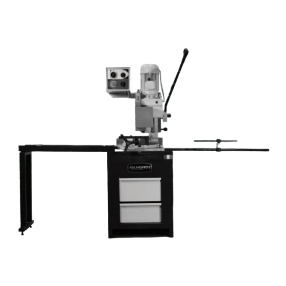
- Page 1 9683338 Operating Instructions & Parts Manual 14.5” Vertical Column Cold Saw 9644664.01...
- Page 2 COULD RESULT IN PERSONAL INJURY AND/OR PROPERTY DAMAGE! RETAIN INSTRUCTIONS FOR FUTURE REFERENCE. PLEASE REFER TO BACK COVER FOR INFORMATION REGARDING PALMGREN’S WARRANTY AND OTHER IMPORTANT INFORMATION. Model #: ___________________ Serial #: ___________________ Purch. Date: _______________ © 2020 Palmgren All Rights Reserved...
-
Page 3: Getting Started
Use soap and water on painted components. Palmgren model 9683338 14.5” Cold Saw is shipped complete in one box. The saw comes assembled as one unit. Additional parts which need to be assembled or fastened to the saw should be... -
Page 4: Safety Rules
SAFETY RULES Preparing the work area for your job • Keep work area clean. Cluttered work areas invite accidents. Completely read and understand this owner’s manual before assembly or tool • Do not use power tools in dangerous environments. Do not operation. -
Page 5: Specifications
United States ANSI Z87.1. operations. before commencing power tool operation. Parameter 9683338 Think safety! Safety is a combination of operator common sense and alertness at all times when tool Description 14" Vertical Column Cold Saw is being used. - Page 6 ASSEMBLY/INSTALLATION Lifting and setting up the saw Make certain that slings, cables, chains, Location forklifts or other load suspending gear or machines used to move this saw are properly rated to The saw must be installed on a structurally stable floor. The handle the weight.
- Page 7 Electrical Connection To The Mains Length Stop NOTE: Install a differential thermomagnetic switch with Slide the two rods into the bracket. Then fit the assembled characteristics suited to the mains. rod into the matching hole on the right side of the vise platform.
- Page 8 Figure 7. Saw Blade Mounting Hardware Remove bolt 114 and outside flange 112. Mount the saw blade on the arbor with teeth of blade oiented counterclockwise (the blade rotates counterclockwise in normal operation). Replace outside flange 112 and bolt. Turn blade clockwise up against drive pins and securely tighten bolt.
-
Page 9: Operation
OPERATION Control Always wear safety glasses complying Fast speed with U.S. ANSI Z87.1 before beginning any Green power light Slow speed setting power tool operation. setting To avoid injury from unexpected starting, whenever changing the saw blade or carrying out adjustments, switch the saw off and remove the power cord from the mains outlet. -
Page 10: Changing Blades
Semi-automatic mode cutting operation: CHANGING BLADES NOTE: Pushing the emergency stop button removes power from To remove and replace the saw blade: the blade motor. Releasing it, pulling it out, connects power to the Make sure the cold saw is disconnected from the power. microswitch in the handle. -
Page 11: Blade Selection
BLADE SELECTION NOTE: Best performance of worm screw worm wheel gearing is guaranteed when circular saw blades with drawing-holes are used. Cutting Capcity (values in parentheses are in mm) 90º 1.18” (30) 2.56” (65) 2.17” x 2.17” (55 x 55) 1.77”... -
Page 12: Troubleshooting Guide
Feed speed too high Reduce feed speed. Blade not perpendicular to workpiece. Adjust blade tracking according to instructions. If this proves unsuccessful, contact Palmgren technical support. Green pilot lamp not No incoming power Check connections at machine and power source. - Page 13 Symptom Possible Cause(s) Corrective Action Motor will not turn Emergency stop engaged Rotate Emergency Stop button to disengage. Electrical power supply Check: the phases; the cables; the plug; the socket. Also check that the motor connections are in place. Trigger switch not activating Check that socket/plug connection from handle to motor is inserted correctly;...
-
Page 14: Maintenance/Repair
MAINTENANCE/REPAIR Cleaning of the coolant tank : Filter check. The coolant tank can be cleaned by simply removing the crucible Replacement of gear box oil 87 (see “Parts List” on page 15). Empty the coolant from the Place a container, labeled to indicate the contents for the tank and collect the coolant in a container for future disposal. - Page 15 Parts List...
- Page 20 Pos. Description Part Number Pos. Description Part Number Not used Not used HH screw M6x12 DIN-933 Not used Hexagon lock-nut M16 DIN-936 Bearing 32006 X Column guard 9644556.01 Worm screw shaft 9644536.01 Washer for M6 DIN-125/A HSHC screw M12x90 DIN-912 HSHC screw M6x12 DIN-912 Vise supporting dowel Rotating plate...
- Page 21 Pos. Description Part Pos. Description Part Number Number Check valve EUROPA 9644579.01 Chip breaker braket 9644607.01 Not used Vise jaw 9644608.01 Not used Side head cover 9644609.01 Oil level cap ø3/8” 9644580.01 0-ring 4362 9644610.01 Cyl. pin M8x25 ( M ) 9644581.01 Vise cylinder ( S ) 9644611.01...
- Page 22 Pos. Description Part Pos. Description Part Number Number Not used Fuse block PCH 2x38 Chip tank 9644628.01 Fuse block PCH 1x38 Electric pump tank 9644629.01 Transformer 20 VA ( M ) 9644648.01 Box bracket support 9644630.01 Transformer 100 VA ( S ) 9644649.01 Box controller 9644631.01...
- Page 24 - 3 YEARS. The obligation of C.H. Hanson / Palmgren is limited solely to the repair or replacement, at our option, at its factory or authorized repair agent of any part that should prove inoperable.
Need help?
Do you have a question about the 9683338 and is the answer not in the manual?
Questions and answers