
Related Manuals for Palmgren 9683122


Summary of Contents for Palmgren 9683122
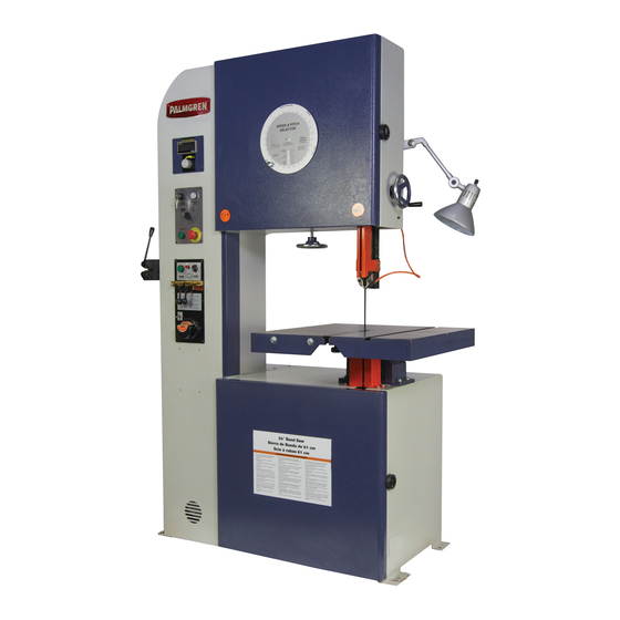
- Page 1 Operating Manual & Parts List 9683122 & 9683123 24˝ Tool Room Saw Read carefully and follow all safety rules and operating instructions before first use of this product. 9645074.01-0420...
-
Page 2: Getting Started
3 HP 3 HP ELECTRICAL REQUIREMENTS Voltage 220V 440V The power supply to Model 9683122 needs to be 220 volt/ 9.7 amp, Amperage 9.7 A 4.9 A three phase, 60 Hz. The standard allowable voltage variation is plus Phase 3 PH 3 PH or minus 10%. -
Page 3: Installation
Model 9683122 is wired for 220 volt, 60 Hz power source. Model 9683123 is wired for 440 volt, 60 Hz power source. TOOL SHOULD BE MAINTAINED The motor is designed for operation on the voltage and frequency •... -
Page 4: Operation
Palmgren Operating Manual & Parts List 9683122 & 9683123 OPERATION CONTROLS Refer to Figures 1, 2 and 3. A. Speed Readout – Displays speed in feet per minute. B. Speed Selection Dial – Variable speed control. C. Power Switch – Main power control with key. - Page 5 Palmgren Operating Manual & Parts List 9683122 & 9683123 OPERATION (CONTINUED) INSTALL NEW SAW BLADE 1. Start by wrapping the new saw blade around the lower wheel. Ensure the blade teeth are facing towards you and down to- Butt back of blade against wards the table.
- Page 6 Palmgren Operating Manual & Parts List 9683122 & 9683123 OPERATION (CONTINUED) TOOTH SPACING Refer to Figure 7. 1. Approximately 1/8” of blade will be consumed during the welding process. This blade loss must be taken into account. 2. All blades must have some of the teeth ground off so that the tooth spacing will be uniform after welding.
-
Page 7: Maintenance
Palmgren Operating Manual & Parts List 9683122 & 9683123 OPERATION (CONTINUED) MAINTENANCE GRINDING BLADE Steps required to keep the saw in optimum operating condition 1. After annealing the blade, the metal buildup or flash must be have been described under “Operating Instructions.” The Safety Pre- ground from the blade. - Page 8 Palmgren Operating Manual & Parts List 9683122 & 9683123 220 V ELECTRICAL DIAGRAM R S T Motor Weld Light Figure 9 – 9683122 electrical diagram, 220 V.
- Page 9 Palmgren Operating Manual & Parts List 9683122 & 9683123 440 V ELECTRICAL DIAGRAM R S T Motor Weld Light Figure 10 – 9683123 electrical diagram, 440 V.
- Page 10 Palmgren Operating Manual & Parts List 9683122 & 9683123 Figure 11 – Repair parts illustration for cabinet.
- Page 11 Palmgren Operating Manual & Parts List 9683122 & 9683123 REPLACEMENT PARTS LIST FOR CABINET Ref. Part Description Number Qty. (Δ) Not shown. ( N/A ) Not available as repair part. (*) Standard hardware item, available locally.
- Page 12 Palmgren Operating Manual & Parts List 9683122 & 9683123 Figure 12 – Repair parts illustration for table and lower guide.
- Page 13 Palmgren Operating Manual & Parts List 9683122 & 9683123 REPLACEMENT PARTS LIST FOR LOWER GUIDE Ref. Part Description Number Qty. Table 9644991.01 Fixing Screw 9644992.01 Tilting (Seat L.R) 9644993.01 Washer M8 Hex Socket Cap M8*1.25P*20mm Trunion Base 9644994.01 Hex bolt M8*1.25P*20mm...
- Page 14 Palmgren Operating Manual & Parts List 9683122 & 9683123 Figure 13 – Repair parts illustration for motor and lower wheel.
- Page 15 Wheel Pulley 9645004.01 Set Screw M12*1.75P*35mm Motor Pulley 9645005.01 Set Screw M8*1.25P*10mm Motor 3 HP, 220 V, 3 PH (Model 9683122) 9645006.01 Motor 3 HP, 440 V, 3 PH (Model 9683123) 9645075.01 Hex Bolt M8*1.25P*25mm Base of Gear Reducer 9645007.01 V-Belt 9645008.01...
- Page 16 Palmgren Operating Manual & Parts List 9683122 & 9683123 Figure 14 – Repair parts illustration for upper wheel.
- Page 17 Palmgren Operating Manual & Parts List 9683122 & 9683123 REPLACEMENT PARTS LIST FOR UPPER WHEEL Ref. Part Description Number Qty. Wheel Upper 9645009.01 Hex Bolt M10*1.5P*10mm Wheel Upper 9645010.01 Hex Nut M20*1.5P Washer M20 Bearing 6206 Bearing Housing 9645011.01 Upper Wheel Shaft 9645012.01...
- Page 18 Palmgren Operating Manual & Parts List 9683122 & 9683123 Figure 15 – Repair parts illustration for guide post.
- Page 19 Palmgren Operating Manual & Parts List 9683122 & 9683123 REPLACEMENT PARTS LIST FOR GUIDE POST Ref. Part Description Number Qty. Hexagon socket bolt M6*1P*20L Flat Washer 6mm Tungsten-support 9645027.01 Guide seat (upper) 9645028.01 B1 Tungs bar crown(upper) 9645029.01 Hexagon Socket bolt M6*1P*20L...
- Page 20 Palmgren Operating Manual & Parts List 9683122 & 9683123 Figure 16 – Repair parts illustration for welding station.
- Page 21 Palmgren Operating Manual & Parts List 9683122 & 9683123 REPLACEMENT PARTS LIST FOR WELDING STATION Ref. Ref. Description Part No. Qty. Description Part No. Qty. Hex Nut Screw AP M6*1.0P*16L Screw AP M6*1.0P*20L Bracket Transformer 9645042.01 Washer M6 Panel Welding 9645055.01...
- Page 22 Palmgren Operating Manual & Parts List 9683122 & 9683123 NOTES...
- Page 23 Palmgren Operating Manual & Parts List 9683122 & 9683123 NOTES...
- Page 24 PALMGREN WARRANTY C.H. Hanson / Palmgren warrants their products to be free of defects in material or workmanship. This warranty does not cover defects due directly or indirectly to misuse, abuse, normal wear and tear, failure to properly maintain the product, heated, ground or otherwise altered, or used for a purpose other than that for which is was intended.
Need help?
Do you have a question about the 9683122 and is the answer not in the manual?
Questions and answers