Advertisement
Quick Links
Advertisement

Related Manuals for Palmgren 9683315


Summary of Contents for Palmgren 9683315
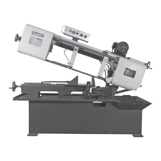
- Page 1 Operating Instructions & Parts Manual 10” Horizontal Mitering Band Saw Model 9683315 9643242.01...
- Page 2 DAMAGE! RETAIN INSTRUCTIONS FOR FUTURE REFERENCE. PLEASE REFER TO BACK COVER FOR INFORMATION REGARDING DAYTON’S WARRANTY AND OTHER IMPORTANT INFORMATION. Model #: ___________________ Serial #: ___________________ Purch. Date: _______________ © 2018 Palmgren / a C.H. Hanson Brand All Rights Reserved...
- Page 3 Electrical requirements of California to cause cancer, birth defects or other The power supply to the Model 9683315, 10” Band Saw reproductive harm. Some examples of these chemicals are: needs to be 220V AC, 3-phase, 3.2 amps, 60 HZ.
- Page 4 SPECIFICATIONS performed. Follow OSHA lock-out, tag-out procedures to prevent accidental machine starts. Model 9683315 - 10” Band Saw • Immediately replace any damaged or obscured warning Motor 2 HP, 1725 RPM, 220V, labels that are attached to the machine.
- Page 5 Remove any crating or overpacking materials which may be Front View covering the machine. Leave the machine attached to the pallet. NOTE: The Model 9683315 Band Saw weighs 1100 lbs. Be 27” certain any machine or devices used to lift the machine are capable of handling this weight.
- Page 6 ASSEMBLY/INSTALLATION - CONTINUED The Model 9683315 Band Saw is fully assembled with exception of the measuring rod and measuring bracket / depth stop. To attach these items: 1. Locate the measuring rod that is packed with the machine. 3. Clean the tank of any dust or dirt that may have accumulated during transit.
- Page 7 L. Blade guides M. Bladewheel covers N. Mechanical motor speed adjustment You can control the depth of cut on the Model 9683315 by This model also uses a hydraulic cylinder and adjustable using the depth stop attachment (V). The attachment slides on counter-balance spring to lower and raise the bow.
- Page 8 To adjust the guide arm. • Loosen the saw guide insert adjustment knob (Z) by The Model 9683315 Band Saw can cut 15˚, 30˚ and 45˚ angles turning it counterclockwise by rotating the saw bow. To change the angle of the saw bow •...
- Page 9 NOTE: You may find it better to cut certain materials 7. Loosen the saw guide inserts by turning the adjusting knob (such as cast iron, aluminum, magnesium, etc.) without counterclockwise. coolant. When dry cutting these materials, follow the 8. Grasp the on the non-cutting edge of the saw blade between same operating procedures used when cutting with coolant.
- Page 10 OPERATING THE BAND SAW - CONTINUED Blade speed adjustment To prevent damage to the band saw, Making a cut speed changes must be made when the machine is running. After your workpiece(s) have been secured and bandsaw properly adjusted as described previously, you can make your cut.
- Page 11 • Parts with large crosscut sections and solid cores need OPERATION - BLADE SELECTION widely spaced teeth to allow for the greater volume of the GUIDELINES shavings and better tooth penetration. Types of materials and blade choices • Parts made of soft material or plastic (light alloys, mild To obtain the best cutting performance from your band saw, bronze, Teflon, wood, etc.
- Page 12 OPERATION - BLADE SELECTION GUIDELINES TEETH PITCH AND RAKE TEETH SET Saw teeth are slightly bent out of the plane of the saw body, resulting in a wide cut in the workpiece. This parameter is called “tooth set.” Regular tooth Regular or raker set 0°...
- Page 13 TROUBLESHOOTING GUIDE Symptom Possible Cause(s) Corrective Action Motor will not start; fuses or circuit 1. Short circuit in line cord or plug 1. Inspect line cord or plug for damaged breakers blow insulation and shorted wires. Replace 2. Short circuit in motor or loose damaged wires and/or components.
- Page 14 TROUBLESHOOTING GUIDE Symptom Possible Cause(s) Corrective Action Tooth breakage Cut advancing too quickly Decrease cutting advance, exerting less cutting pressure. Adjust the braking device. Wrong cutting speed Change speed and/or type of blade. See OPERATION - BLADE SELECTION GUIDELINES beginning on page 11. Wrong tooth pitch Replace blade choosing the proper tooth pitch.
- Page 15 TROUBLESHOOTING GUIDE Symptom Possible Cause(s) Corrective Action Premature blade wear Faulty running-in of blade See OPERATION - BLADE SELECTION GUIDELINES beginning on page 11. Teeth positioned in the direction opposite Remove the blade and reinstall it with the teeth of the cutting direction cutting in the proper direction.
- Page 16 TROUBLESHOOTING GUIDE Symptom Possible Cause(s) Corrective Action Blade breakage/damage Blade guide pads not adjusted properly or Check the adjustment of the blade guides. dirty because of lack of maintenance See OPERATION SET-UP / Blade guide insert adjustments on page 8. Extremely tight tolerance guiding may cause cracks and breakage of teeth.
- Page 17 TROUBLESHOOTING GUIDE Symptom Possible Cause(s) Corrective Action Faulty cut Worn out bandwheels. Flywheel housing The support and guide flange of the bandwheels full of chips are so worn they cannot maintain the proper alignment of the blade causing’ faulty cutting. The blade rolling and drawing tracks can have become tapered.
- Page 18 MAINTENANCE - MODEL 9683315 – 10” BAND SAW The maintenance jobs are listed below, divided into daily, weekly, Drive belt monthly and six-monthly intervals. If the following operations are neglected, the result will be premature wear of the machine and poor performance.
- Page 19 LUBRICATION SCHEDULE - MODEL 9683315 – 10” BAND SAW REF. NO. LOCATION DESCRIPTION LUBRICATION and SERVICE RECOMMENDATIONS INTERVAL* Band Tension Screw. Clean and apply grease. MONTHLY Vise Clamp Screw. Clean and apply grease. MONTHLY Drive Motor Slide. Clean and apply grease.
- Page 20 WIRING DIAGRAM - MODEL 9683315 – 10” BAND SAW...
- Page 21 ELECTRICAL CONTROL SYSTEMS - MODEL 9683315 – 10” BAND SAW FUSE LOCK MOTOR OUTS CONTACTORS SAFETY LOCK OVER TRANSFORMER LOAD FOR THE COILS...
- Page 22 REPAIR PARTS ILLUSTRATION FOR MODEL 9683315 - 10” BAND SAW - SECTION A...
- Page 23 REPAIR PARTS LIST FOR MODEL 9683315 – 10” BAND SAW - SECTION A Ref. Ref. Description Part No. Qty. Description Part No. Qty. Idle Wheel Cover 9643071.01 Shaft 9643103.01 Door Lock 9643072.01 Idle Wheel 9643104.01 Round Head Screw M3x12 Cover (Back) 9643105.01...
- Page 24 REPAIR PARTS ILLUSTRATION FOR MODEL 9683315 - 10” BAND SAW - SECTION A...
- Page 25 REPAIR PARTS LIST FOR MODEL 9683315 – 10” BAND SAW - SECTION A Ref. Ref. Description Part No. Qty. Description Part No. Qty. Motor Base 9643151.01 Washer Half Button Head Socket Screw 5x10 Lock Washer M12 Saw Bow Cover 9643152.01 Hex.
- Page 26 REPAIR PARTS ILLUSTRATION FOR MODEL 9683315 - 10” BAND SAW - SECTION B...
- Page 27 REPAIR PARTS LIST FOR MODEL 9683315 – 10” BAND SAW - SECTION B Ref. Ref. Description Part No. Qty. Description Part No. Qty. Hex. Socket Cap Screw 3/8"x4" Driver Shaft 9643174.01 Washer 3/8" Shaft Bushing 9643175.01 Tension Spring 9643168.01 Driver Wheel 9643176.01...
- Page 28 REPAIR PARTS ILLUSTRATION FOR MODEL 9683315 - 10” BAND SAW - SECTION C...
- Page 29 REPAIR PARTS LIST FOR MODEL 9683315 – 10” BAND SAW - SECTION C Ref. Ref. Description Part No. Qty. Description Part No. Qty. Machine Base 9643181.01 Thread M16x260L 9643207.01 Flat Head Soc. Screw M6x12 Spring Pin 06x3OL 9643208.01 Angle Cutting Board 9643182.01...
- Page 30 REPAIR PARTS ILLUSTRATION FOR MODEL 9683315 - 10” BAND SAW - SECTION C...
- Page 31 REPAIR PARTS LIST FOR MODEL 9683315 – 10” BAND SAW - SECTION C Ref. Ref. Description Part No. Qty. Description Part No. Qty. 106 Lock Washer M8 112 Lock Handle 9643246.01 107 Spring Hook 9643239.01 113 Work Stop bracket 9643247.01 108 Ball Plunger Seat 9643240.01...
- Page 32 - 3 YEARS. The obligation of C.H. Hanson / Palmgren is limited solely to the repair or replacement, at our option, at its factory or authorized repair agent of any part that should prove inoperable.
Need help?
Do you have a question about the 9683315 and is the answer not in the manual?
Questions and answers