
Related Manuals for Palmgren 9683277


Summary of Contents for Palmgren 9683277
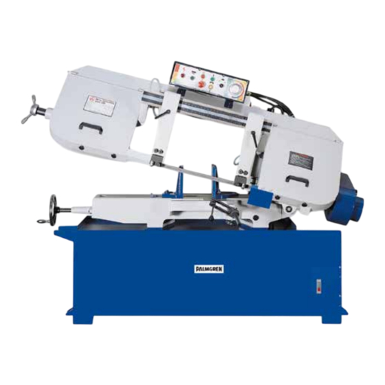
- Page 1 Operating Instructions & Parts Manual 13” x 19” Variable Speed Semi-Automatic Horizontal Bandsaw Model 9683277, 230V, 3PH 965102401 - 01/24...
- Page 2 INJURY AND/OR PROPERTY DAMAGE! RETAIN INSTRUCTIONS FOR FUTURE REFERENCE. PLEASE REFER TO BACK COVER FOR INFORMATION REGARDING PALMGREN’S WARRANTY AND OTHER IMPORTANT INFORMATION. Model #: ___________________ Serial #: ___________________ Purch. Date: _______________ © 2024 Palmgren Electric Manufacturing Co. All Rights Reserved...
-
Page 3: Getting Started
Wear proper apparel. Do not wear loose clothing, gloves, Electrical requirements neckties, rings, bracelets, or other jewelry which may get The power supply to the 9683277 bandsaw must be caught in moving parts of machine. 230 VAC, 3-phase, 60 Hz. -
Page 4: Installation Safety
Installation Safety Think safety! Safety is always a combination of operator common sense and alertness when tool is being used. • Ensure the installation location can support the weight of Operating Safety the machine and has adequate space, ventilation, and heat Before starting machine check: dissipation. -
Page 5: Specifications
Blade Selection Never use a blade so coarse that less than 3 teeth are engaged Description Palmgren Variable Speed in the workpiece at a time. Too few teeth causes teeth to strip out. Horizontal Bandsaw 13” x 19” Never use a blade finer than needed to obtain a satisfactory... -
Page 6: Installation
INSTALLATION Assembly Insert stop rod in to the base below the vise. Place work stop Moving Bandsaw bracket onto stop rod and tighten lock handle. Attach stop screw The bandsaw must be installed on a solid, level foundation. to stop bracket with lock handle and tighten. Choose a location that allows room for servicing and for moving Electrical Wiring large stock around the bandsaw. -
Page 7: Operation
Materials and Speeds Refer to Figure 5. The Cutting Pressure Control provides a guide to the best setting range to use for materials of different hardness. A (Light blue): Hard Metals B (Green) - Medium Hard Metals C (Yellow): Soft Metals D (Orange): Soft Materials) E (Blue-Red): Rapid Down Feed Figure 3. -
Page 8: Automatic Shut-Off
Changing Blade Speed Down-Bow Dampener NOTE: Bandsaw must be running in order to adjust blade To produce a better cut, this bandsaw reduces the rate of speed. down-bow when the blade approaches the table. The saw is equipped with a standard (inch) size blade at the factory The dial protruding from the motor cover (right side) controls the Because the width of standard size and metric size blades are speed between 66 FPM to 264 FPM. -
Page 9: Troubleshooting
TROUBLESHOOTING Cleaning Chips The chip cleaner attaches to the coolant pump and is stored in the front locker (Figure 10, A. To operate, open valve (Figure 9, Make certain that the bandsaw is A) and use hand nozzle to spray (Figure 10, B). disconnected from power source before attempting to service or remove any component. -
Page 10: Blade Tracking Adjustment
Even dull blades are sharp to the skin! Use extra caution handling bandsaw blades! Install new blade, ensuring teeth point downward in the proper cutting direction. If necessary, turn blade inside out. Position blade on band wheels and tighten just enough to hold blade on wheels. -
Page 11: Automatic Shut-Off Adjustment
NOTE: Over-tracking (allowing blade back to rub hard against NOTE: Blade should travel freely up and down between the wheel flange) will damage the blade wheels and blade. ball bearings. Do not pinch the blade. Tighten locking bolts (A) when tracking adjustment is Tighten locking screws (Figure 17, A). -
Page 12: Changing Gear Box Oil
Changing Gear Box Oil To adjust vise for angle cutting: Loosen bolts and move vise jaw (Figure 19, A) to desired The gear box lubricant should be changed after the first 3 months angle. of operation. Change lubricant from then on every year. Tighten bolts and adjust movable vise parallel to fixed vise To change gear box lubricant: by loosening bolts (Figure 18, B), adjusting to match parallel. -
Page 13: Parts List
PARTS LIST Figure 20. Parts Diagram - Sheet 1 of 2... - Page 14 Figure 21. Parts Diagram - Sheet 2 of 2...
- Page 15 Ref. Description Part Ref. Description Part Numbers Numbers Base 965132901 21-1 Set Screw 5/16 x3/8 Hex. Cap Bolt M12x65 21-2 Handle 965135801 Nut M12 Rack 965135901 Coolant Pump 1/6HP 965133001 Lead Screw Seat 965136001 Round Head Screw M6x16 23-1 Hex. Socket Cap Screw M8x20 Set Screw M8x16 23-2 Hex.
- Page 16 Ref. Description Part Ref. Description Part Numbers Numbers Round Head Screw M5x35 74-1 Magnetic Switch M2 965140301 44-1 Spring Washer M5 74-2 Magnetic Switch M3 965140401 Limit Switch 5101 965137401 74-3 Magnetic Switch M1 965140501 45-1 Roller Limit Switch 5102 965137501 74-4 Overload Relay (oil pump)
-
Page 17: Part Numbers
Ref. Description Part Ref. Description Part Numbers Numbers 95-1 Hex. Cap Bolt M6x12 125-3 Washer M6 95-2 Spring Washer M6 Adjusting Bracket Mount-Right 965145501 95-3 Washer M6 126-1 Adjusting Bracket Mount-Left 965145601 Pulley Cover 965143101 Lock Block 965145701 Idle Pulley 965143201 Handle 965145801... - Page 18 Ref. Description Part Ref. Description Part Numbers Numbers Stop Switch 965147701 171-1 Sleeve M20x35 Emergency Switch 965147801 171-2 Spring Washer M12 Bow-Up Switch 965147901 171-3 Hex. Cap Bolt M12x70 Bow-Down Switch 965148001 Blade Tension Scale 965149401 On/Off Coolant Switch 965148101 172-1 Round Head Screw M5x10 Speed Control Switch...
- Page 20 PALMGREN WARRANTY C. H. Hanson / Palmgren warrants their products to be free of defects in material or workmanship. This warranty does not cover defects due directly or indirectly to misuse, abuse, normal wear and tear, failure to properly maintain the product, heated, ground or otherwise altered, or used for a purpose other than that for which is was intended.
Need help?
Do you have a question about the 9683277 and is the answer not in the manual?
Questions and answers