Table of Contents
Advertisement
Quick Links
Advertisement
Table of Contents

Related Manuals for Palmgren 9683120


Summary of Contents for Palmgren 9683120
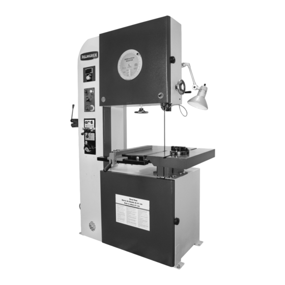
- Page 1 9683120_9683121_oipm_En011_9645072.01-0620 __ 06-24-2020 Operating Manual & Parts List 9683120 & 9683121 20˝ Tool Room Saws Read carefully and follow all safety rules and operating instructions before first use of this product. 9645072.01-0620...
-
Page 2: Getting Started
ELECTRICAL REQUIREMENTS Some examples of these chemicals are: The power supply to Model 9683120 needs to be 220 volt/ 6.5 amp, • Lead from lead-based paints three phase, 60 Hz. The standard allowable voltage variation is plus or minus 10%. -
Page 3: Specifications
• Never stand on tool. Serious injury could occur if tool is tipped or Model 9683120 is wired for 220 volt, 60 Hz power source. if blade is unintentionally contacted. Model 9683121 is wired for 440 volt, 60 Hz power source. -
Page 4: Extension Cords
9683120_9683121_oipm_En011_9645072.01-0620 __ 06-24-2020 Palmgren Operating Manual & Parts List 9683120 & 9683121 INSTALLATION (CONTINUED) A. Speed Readout – Displays speed in feet per minute. EXTENSION CORDS B. Speed Selection Dial – Variable speed control. • The use of any extension cord will cause some drop in voltage C. -
Page 5: Blade Welding
9683120_9683121_oipm_En011_9645072.01-0620 __ 06-24-2020 Palmgren Operating Manual & Parts List 9683120 & 9683121 OPERATION (CONTINUED) PREPARING BLADE FOR WELDING 1. A properly prepared blade is essential in producing a high- INSTALLING/REPLACING BLADE quality, long lasting band saw blade. WARNING: Ensure the saw is disconnected from power supply, so 2. -
Page 6: Blade Mounting
9683120_9683121_oipm_En011_9645072.01-0620 __ 06-24-2020 Palmgren Operating Manual & Parts List 9683120 & 9683121 OPERATION (CONTINUED) Tooth BLADE MOUNTING Tooth Tooth Refer to Figure 6. Tooth 4TPI 1. Clean welder jaw of any scale, oil, rust or dirt. Clean blade ends 12TPI which contact welder jaws to provide proper electrical contact. -
Page 7: Maintenance
9683120_9683121_oipm_En011_9645072.01-0620 __ 06-24-2020 Palmgren Operating Manual & Parts List 9683120 & 9683121 OPERATION (CONTINUED) GRINDING BLADE 1. After annealing the blade, the metal buildup or flash must be WARNING: Welding operation produces sparks at blade intersection. ground from the blade. - Page 8 9683120_9683121_oipm_En011_9645072.01-0620 __ 06-24-2020 Palmgren Operating Manual & Parts List 9683120 & 9683121 220 V ELECTRICAL DIAGRAM R S T Motor Weld Light Figure 9 – 9683120 electrical diagram, 220 V.
- Page 9 9683120_9683121_oipm_En011_9645072.01-0620 __ 06-24-2020 Palmgren Operating Manual & Parts List 9683120 & 9683121 440 V ELECTRICAL DIAGRAM R S T Motor Weld Light Figure 10 – 9683121 electrical diagram, 440 V.
- Page 10 9683120_9683121_oipm_En011_9645072.01-0620 __ 06-24-2020 Palmgren Operating Manual & Parts List 9683120 & 9683121 18-1 Figure 11 – Repair parts illustration for cabinet.
- Page 11 9683120_9683121_oipm_En011_9645072.01-0620 __ 06-24-2020 Palmgren Operating Manual & Parts List 9683120 & 9683121 REPLACEMENT PARTS LIST FOR CABINET Ref. Description Part Number: Qty. Wheel Door Lower 9645365.01 Hinge Pin Lower 9645366.01 Phillips Head Screw M5 × 0.8 × 8mm Control Panel 9645367.01...
- Page 12 9683120_9683121_oipm_En011_9645072.01-0620 __ 06-24-2020 Palmgren Operating Manual & Parts List 9683120 & 9683121 Figure 12 – Repair parts illustration for table and lower guide.
- Page 13 9683120_9683121_oipm_En011_9645072.01-0620 __ 06-24-2020 Palmgren Operating Manual & Parts List 9683120 & 9683121 REPLACEMENT PARTS LIST FOR TABLE AND LOWER GUIDE Ref. Description Part Number: Qty. Table 9645387.01 Fixing Screw 9645388.01 Tilting (Seat L.R) 9645389.01 Washer M8 Hex Socket Cap M8 × 1.25P × 20mm Trunnion Base 9645390.01...
- Page 14 9683120_9683121_oipm_En011_9645072.01-0620 __ 06-24-2020 Palmgren Operating Manual & Parts List 9683120 & 9683121 Figure 13 – Repair parts illustration for motor and lower wheel.
- Page 15 9683120_9683121_oipm_En011_9645072.01-0620 __ 06-24-2020 Palmgren Operating Manual & Parts List 9683120 & 9683121 REPLACEMENT PARTS LIST FOR MOTOR AND LOWER WHEEL Ref. Description Part Number: Qty. Wheel Lower 9645395.01 Hex Bolt M10 × 1.5P × 10mm Bearing 6206 Key 8 × 8 × 20 Lower Wheel Shaft 9645399.01...
- Page 16 9683120_9683121_oipm_En011_9645072.01-0620 __ 06-24-2020 Palmgren Operating Manual & Parts List 9683120 & 9683121 Figure 14 – Repair parts illustration for upper wheel.
- Page 17 9683120_9683121_oipm_En011_9645072.01-0620 __ 06-24-2020 Palmgren Operating Manual & Parts List 9683120 & 9683121 REPLACEMENT PARTS LIST FOR UPPER WHEEL Ref. Description Part Number: Qty. Wheel Upper 9645405.01 Hex Bolt M10 × 1.5P × 10mm Retaining Ring STW-30# Bearing 6206 Bearing Housing 9645406.01...
- Page 18 9683120_9683121_oipm_En011_9645072.01-0620 __ 06-24-2020 Palmgren Operating Manual & Parts List 9683120 & 9683121 Figure 15 – Repair parts illustration for guide post.
- Page 19 9683120_9683121_oipm_En011_9645072.01-0620 __ 06-24-2020 Palmgren Operating Manual & Parts List 9683120 & 9683121 REPLACEMENT PARTS LIST FOR GUIDE POST Ref. Description Part Number: Qty. Hexagon Socket Bolt M6 × 1P × 20L Flat Washer 6mm Tungsten Support 9645422.01 Guide Seat (Upper) 9645423.01...
- Page 20 9683120_9683121_oipm_En011_9645072.01-0620 __ 06-24-2020 Palmgren Operating Manual & Parts List 9683120 & 9683121 Figure 16 – Repair parts illustration for welding station.
- Page 21 9683120_9683121_oipm_En011_9645072.01-0620 __ 06-24-2020 Palmgren Operating Manual & Parts List 9683120 & 9683121 REPLACEMENT PARTS LIST FOR WELDING STATION Ref. Description Part Number: Qty. Hex Nut, M6 x 9 Bracket Transformer 9645437.01 Washer M6 Nut M6 Sensor 9645438.01 Hexagon Socket Bolt M6*1.0P*25L Hexagon Socket Bolt M6*1.0P*10L...
- Page 22 9683120_9683121_oipm_En011_9645072.01-0620 __ 06-24-2020 Palmgren Operating Manual & Parts List 9683120 & 9683121 NOTES...
- Page 23 9683120_9683121_oipm_En011_9645072.01-0620 __ 06-24-2020 Palmgren Operating Manual & Parts List 9683120 & 9683121 NOTES...
- Page 24 9683120_9683121_oipm_En011_9645072.01-0620 __ 06-24-2020 PALMGREN WARRANTY C.H. Hanson / Palmgren warrants their products to be free of defects in material or workmanship. This warranty does not cover defects due directly or indirectly to misuse, abuse, normal wear and tear, failure to properly maintain the product, heated, ground or otherwise altered, or used for a purpose other than that for which is was intended.
Need help?
Do you have a question about the 9683120 and is the answer not in the manual?
Questions and answers