
Related Manuals for Palmgren 9683275


Summary of Contents for Palmgren 9683275
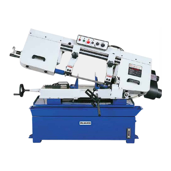
- Page 1 Operating Instructions & Parts Manual 10” x 16” Variable Speed Horizontal Bandsaw Models 9683275, 9683276 965102201 - 01/24...
- Page 2 INJURY AND/OR PROPERTY DAMAGE! RETAIN INSTRUCTIONS FOR FUTURE REFERENCE. PLEASE REFER TO BACK COVER FOR INFORMATION REGARDING PALMGREN’S WARRANTY AND OTHER IMPORTANT INFORMATION. Model #: ___________________ Serial #: ___________________ Purch. Date: _______________ © 2023 Palmgren Electric Manufacturing Co. All Rights Reserved...
-
Page 3: Getting Started
Wear proper apparel. Do not wear loose clothing, gloves, Electrical requirements neckties, rings, bracelets, or other jewelry which may get The power supply to the 9683275 single-phase caught in moving parts of machine. bandsaw must be 240 VAC, single-phase, 60 Hz. -
Page 4: Installation Safety
Installation Safety Operating Safety Before starting machine check: • Ensure the installation location can support the weight of the machine and has adequate space, ventilation, and heat • KEEP GUARDS IN PLACE AND IN WORKING ORDER. dissipation. • KEEP WORK AREA CLEAN. Cluttered areas and benches •... -
Page 5: Specifications
Too few teeth causes teeth to strip out. Bandsaw 10” x 16” Never use a blade finer than needed to obtain a satisfactory Model number and 9683275 (single-phase) surface finish or satisfactory flatness. Too many teeth slows down Phase 9683276 (three-phase) the sawing rate;... -
Page 6: Installation
Electrical Wiring machine is moved improperly. Follow the instructions and information on the transport crate. Check Model 9683275 Single-Phase that the lifting and load suspension equipment has sufficient load capacity and that it is in perfect condition. See Figure 2. Connect the bandsaw to the electrical source as shown. -
Page 7: Setting Up The Machine For Operation
OPERATION Model 9683276 Three-Phase See Figure 3. Connect the bandsaw to the electrical source as Setting Up the Machine for Operation shown. Refer to the wiring diagram inside the electrical box for NOTE: You must fill the coolant tank before the first use of proper motor and transformer connections, lead selection and the saw. -
Page 8: Maintenance
MAINTENANCE Removing and Installing the Blade A blade is installed in the saw at the factory. When selecting a new blade refer to the selection of sawblades. The bandsaw requires a blade 1” x 0.032” x 130”. To replace the blade: Disconnect the power source. -
Page 9: Blade Tracking Adjustment
Figure 10. Blade Tracking Adjustment Adjusting Feed Rate Figure 9. Working Blade Around Wheels When the hydraulic oil regulating control (Figure 11, A) is turned 11. When you are sure the back of the blade is against the all the way clockwise, the saw frame will not move down. By wheel flanges of both wheels and properly inserted into the turning the feed control counter-clockwise, you regulate the flow guides, finish putting tension on the blade. -
Page 10: Automatic Shut-Off Adjustment
Guide Roller Adjustment Disconnect machine from the power source. See Figure 14. Loosen blade guides (A) by loosening screws (B). Slide blade guides away from blade. Use a hex wrench to loosen locking screws (C). Adjust the eccentric bushings with a combination wrench until the ball bearings are snug to the blade. - Page 11 Lubrication The following lubricants are used with this bandsaw: • Coolant: Use water-soluble cutting fluid ##### • Gear oil: HD-150 • Hydraulic system: #32 / #68 Changing Gear Box Oil After the first 50 hours of use, drain and refill the gear box by doing the following: See Figure 16.
-
Page 12: Parts List
PARTS LIST Figure 17. Parts Diagram - Sheet 1 of 2... - Page 13 Figure 18. Parts Diagram - Sheet 2 of 2...
- Page 14 Ref. Description Part Ref. Description Part Numbers Numbers Base 965118101 Torsion Spring Shaft 965121001 Hex. Cap Bolt M12x65 C-Ring S-22 Nut M12 Hex. Cap Bolt M8x30 Coolant Pump 965118701 39-1 Washer M8 Round Head Screw M6x16 39-2 Nut M8 Lock Washer M6 Motor Tilt Plate 965121101 Hose...
- Page 15 Ref. Description Part Ref. Description Part Numbers Numbers 70-1 965122801 Column 965125701 Fuse Block 1A 965122901 Hex. Socket Cap Screw M12x20 71-1 Fuse Block 2A 965123001 106-1 Lock Washer M12 Contactor (main motor) 965123101 106-2 Nut M12 72-1 Contactor (pump) 965123201 72-2 Overload Relay...
- Page 16 Ref. Description Part Ref. Description Part Numbers Numbers 133-1 Washer M8 Handle 965129801 Adjustable Bracket-Left 965126801 Nut M12 Scale 965126901 Round Head Screw M5x10 135-1 Round Head Screw 965127001 Indicator Scale 965129901 Hex. Socket Cap Screw Slide Bracket 965130001 M10x25 Tension Shaft 965130101 Slide...
- Page 17 Ref. Description Part Numbers Variable Speed Adjustable 965132201 V100 Pulley Cover 965132301 V101 Support Shaft 965132401 V101-1 Knob 3/8” 965132501 V101-2 Washer M10 V101-3 Nut 5/16” V101-4 Lock Washer M8 * Hardware item, available locally...
- Page 18 PALMGREN WARRANTY C. H. Hanson / Palmgren warrants their products to be free of defects in material or workmanship. This warranty does not cover defects due directly or indirectly to misuse, abuse, normal wear and tear, failure to properly maintain the product, heated, ground or otherwise altered, or used for a purpose other than that for which is was intended.
Need help?
Do you have a question about the 9683275 and is the answer not in the manual?
Questions and answers