
Related Manuals for Palmgren 9684486


Summary of Contents for Palmgren 9684486
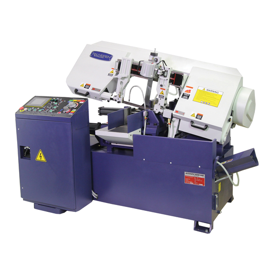
- Page 1 Operating Instructions & Parts Manual 10” Automatic Horizontal Band Saw Model 9684486 9640127.02...
- Page 2 DAMAGE! RETAIN INSTRUCTIONS FOR FUTURE REFERENCE. PLEASE REFER TO BACK COVER FOR INFORMATION REGARDING PALMGREN’S WARRANTY AND OTHER IMPORTANT INFORMATION. Model #: ___________________ Serial #: ___________________ Purch. Date: _______________ © 2017 Palmgren / a C.H. Hanson Brand All Rights Reserved...
-
Page 3: Getting Started
Be sure that the voltage labeled on the unit matches your power supply. Electrical requirements SAFETY RULES The power supply to the Model 9684486 Fully Automatic Band Saw needs to be 220V DC, 9 amps, 60 For you own safety, read all of the instructions and precautions before The control circuit voltage for this machine is 24V and operating the tool. -
Page 4: Specifications
SPECIFICATIONS • Replacement parts and accessories. When servicing, use Model 9684486 - 10” Fully Automatic Band Saw only identical replacement parts. Use of any other parts will Main Motor 3 HP void the warranty. Only use accessories intended for use with this tool. -
Page 5: Operation
SPECIFICATIONS (CONTINUED) Securing the machine to the foundation • Position the machine on a flat and level foundation of Bundle Cutting (W x H) 6" to 9-3/4" x 4" to 5" reinforced concrete. The foundation must be strong enough to Cut off Length 0.39"... - Page 6 OPERATION - DESCRIPTION OF MACHINE PARTS AND FUNCTIONS The machine control panel A. Control Panel (Interface Control Screen) K. Shuttle Vise Open Button Press the hydraulic start button B to start. Press and hold the button to adjust the vise to a desired length. The button opens one full length when saw bow is at the safe B.
- Page 7 Use extreme caution when placing, positioning and clamping stock with the vise clamps. The Model 9684486 Automatic Band Saw is equipped with automatic power shut-off safety sensor (3A) to help prevent machine damage when a blade has been broken.
-
Page 8: Limit Switches
The forward limit switch limit switch (5A) stops the shuttle vise. OPERATION - DESCRIPTION OF MACHINE Two similar switches (6A, 7A) are positioned on the hydraulic PARTS AND FUNCTIONS - CONTINUED cylinder of the saw bow to limit the saw bow stroke. The vertical rollers (6A) Bow down limit switch The vertical rollers (4A) assist the machine by giving support to... - Page 9 7. The Alarm Display Shows error notices when machine Interface Control Screen - Main (Home) Menu - F1 malfunctions occur and how to solve them. This page also records the history alarm data. Check the error data by moving right side vertical and horizontal arrow signs.
- Page 10 Interface Control Screen - Current Operations - F2 Interface Control Screen - Cutting Jobs Settings - F3 (Continued) 18. Count Trim Cut In or Out The F3 button for will display the screen shown above. Touch this button to count trim cut in or out after starting automatic cutting cycle.
-
Page 11: Removing And Installing The Blade
22. Shows Manual or Auto Mode OPERATION - SAW BLADE INSTALLATION AND GUIDE ADJUSTMENT 23. Touch to clear all set data (back) to zero setting. Choose Yes or No from the Always disconnect the machine from its power source before changing blades or following dialogue box carrying out any maintenance procedure even in the case of irregular machine operation. -
Page 12: Blade Tracking Adjustment
Breaking in the new saw blade When a new blade is installed, be sure to break in the blade before using it for production. Failure to break in the blade will shorten the service life of the blade, and result in less than optimum performance. -
Page 13: Operation - Preparations
NOTE: Over tracking (allowing blade back to rub hard against • The machine will automatically clamp the material in auto wheel flange) will damage the blade wheels and blade. mode and the vise can close a full stroke to do so. •... -
Page 14: Operation Cycles
• Roughly, the ratio of feed speeds should be 1:2:3. The the width of vertical press (13B) to suit bundle material width, materials are listed on the control panel. Please refer to it for after setting tighten the side screws. proper cutting pressure setting. -
Page 15: Automatic Operation
• Place the workpiece onto the vise. (Refer to Securing the Automatic operation Workpiece, pg. 13). • Close the shuttle vises use the shuttle vise close button (J). • Move the workpiece to the desired position. Use the shuttle vise Forward and Backward Buttons (L and M) •... - Page 16 OPERATION - MISCELLANEOUS Coolant heater operation Bundle cutting Begin by attaching the nestling clamps to the vises; refer to Attach the Nestling Clamps (pg. 14). • Follow either the Manual Operation (pg. 15) procedures or the Automatic Operation (pg. 16) procedures. •...
- Page 17 NOTES...
- Page 18 OPERATION - MACHINE AND STEEL REFERENCE INFORMATION Machine capacities and specifications Electric motor ............3 HP Blade size ..........1” x .035” x 138” 9-13/16” 9-13/16” Blade speed ..........65 to 262 FPM x 11-13/16” Working table height ..........29-1/2”” 6” to 9-3/4” x 4” to 5” Machine weight ..........
-
Page 19: Troubleshooting Guide
TROUBLESHOOTING GUIDE The Interface Control Screen will show error notices when machine malfunctions occur. They will display the probable causes and possible remedies. Follow the remedies to resolve the problem and press reset button to remove the Error Notice. The diagram on the left shows a map with numbers identifying the location of various malfunctions. - Page 20 TROUBLESHOOTING GUIDE Symptom Possible Cause(s) Corrective Action Tooth breakage Cut advancing too quickly Decrease cutting advance, exerting less cutting pressure. Adjust the braking device. Wrong cutting speed Change speed and/or type of blade to better match the material being cut. Wrong tooth pitch Replace blade choosing the proper tooth pitch to better match the material being cut.
- Page 21 TROUBLESHOOTING GUIDE Symptom Possible Cause(s) Corrective Action Premature blade wear Faulty blade break-in Break in a new blade. (See pgs. 12 and 13) Teeth positioned in the direction opposite Remove the blade and reinstall it with the teeth of the cutting direction cutting in the proper direction.
- Page 22 TROUBLESHOOTING GUIDE Symptom Possible Cause(s) Corrective Action Blade breakage/damage Blade guide not adjusted properly or dirty Check, clean and adjust the blade tracking to because of lack of maintenance. ensure the blade travels freely and true. (See pg. 13) Blade guide block too far from material to Set the approach head closely to the material be cut being cut so that only the blade section used in...
- Page 23 TROUBLESHOOTING GUIDE Symptom Possible Cause(s) Corrective Action Blade cuts crooked Cut advancing too fast Decrease the speed of the cut advance, exerting less cutting pressure. Adjust the braking device. Worn out blade Move the blade close to material being cut so that only the blade section used in the cut is free, This will prevent deflections that would excessively stress the blade.
- Page 24 MODEL 9684486 10” AUTOMATIC BAND SAW - WIRING DIAGRAM NO. 1 +24V...
- Page 25 MODEL 9684486 10” AUTOMATIC BAND SAW - WIRING DIAGRAM NO. 2 M.C of U2 Working Lamp Blade Lamp Hydraulic Lamp Coolant Lamp Protected Circuit...
- Page 26 MODEL 9684486 10” AUTOMATIC BAND SAW - WIRING DIAGRAM NO. 3...
- Page 27 MODEL 9684486 10” AUTOMATIC BAND SAW - WIRING DIAGRAM NO. 4 Valve of Vise Base To Front Alarm for U2 Valve of Vise Base To Rear O.L of M2 Relay of M1 Start M.C of M2 O.L of M3 M.C of M3...
- Page 29 REPAIR PARTS LIST FOR MODEL 9684486 – 10” FULLY AUTOMATIC BAND SAW - SECTION A Ref. Ref. Description Part No. Qty. Description Part No. Qty. Screw M6x8 Cylinder Support Rod 9640729.01 Control Panel 9640695.01 Socket Head Bolt M12x65 Control Box Door 9640696.01...
- Page 30 REPAIR PARTS ILLUSTRATION FOR MODEL 9684486 – 10” FULLY AUTOMATIC BAND SAW - SECTION B For Repair Parts, call 1-800-Grainger Please provide following information: -Model number -Serial number (if any) 24 hours a day – 365 days a year -Part description and number as shown in parts list...
- Page 31 REPAIR PARTS LIST FOR MODEL 9684486 – 10” FULLY AUTOMATIC BAND SAW - SECTION B Ref. Ref. Description Part No. Qty. Description Part No. Qty. Emergency Stop Button 9640765.01 Coolant Motor Overload Relay 9640791.01 Power Indicator Light 9640766.01 Hydraulic Motor Overload Relay 9640792.01...
- Page 33 REPAIR PARTS LIST FOR MODEL 9684486 – 10” FULLY AUTOMATIC BAND SAW - SECTION C Ref. Ref. Description Part No. Qty. Description Part No. Qty. Bench Vise Cylinder 9640814.01 O Ring 9640839.01 Socket Head Bolt M16x55 Nut M16 Rod Pin 9640815.01...
- Page 35 REPAIR PARTS LIST FOR MODEL 9684486 – 10” FULLY AUTOMATIC BAND SAW - SECTION D Ref. Ref. Description Part No. Qty. Description Part No. Qty. Blade 9640861.01 Sensor Probe Plate 9640889.01 Screw M6x12 Probe Plate Seat 9640890.01 Blade Cover 9640862.01...
- Page 37 REPAIR PARTS LIST FOR MODEL 9684486 – 10” FULLY AUTOMATIC BAND SAW - SECTION D (CONTINUED) Ref. Ref. Description Part No. Qty. Description Part No. Qty. Upper Arm Base 9640904.01 D112 Socket Head Bolt M16x70 Flat Washer M8 D113 Lock Washer M16...
- Page 39 REPAIR PARTS LIST FOR MODEL 9684486 – 10” FULLY AUTOMATIC BAND SAW - SECTION E Ref. Ref. Description Part No. Qty. Description Part No. Qty. Nut M10 Adjusting Screw (L) 9640619.01 Lock Washer M10 Spring 9640620.01 Flat Washer M10 Steel Pin M10x30 Brush 9640606.01...
- Page 41 REPAIR PARTS LIST FOR MODEL 9684486 – 10” FULLY AUTOMATIC BAND SAW - SECTION F Ref. Ref. Description Part No. Qty. Description Part No. Qty. Screw M5x8 Flat Washer M10 Cover 9640634.01 Hex Bolt M10x25 Oil Seal 130.160.14 9640635.01 Lock Washer M10 Rubber Ring 9640636.01...
- Page 43 REPAIR PARTS LIST FOR MODEL 9684486 – 10” FULLY AUTOMATIC BAND SAW - SECTION G (OPTIONAL) Ref. Ref. Description Part No. Qty. Description Part No. Qty. O Ring 9640669.01 Press Plate (R,L) 9640678.01 Cylinder (Long) 9640670.01 Socket Head Bolt 9640679.01 O Ring 9640671.01...
- Page 45 REPAIR PARTS LIST FOR MODEL 9684486 – 10” FULLY AUTOMATIC BAND SAW - SECTION H Ref. Ref. Description Part No. Qty. Description Part No. Qty. Set Screw M6x6 Temp. Control Power Light 9640690.01 Fixing Bracket 9640686.01 Temp. Control Switch 9640691.01 Heater Tube 9640687.01...
-
Page 46: Routine And Special Maintenance
ROUTINE AND SPECIAL MAINTENANCE Monthly maintenance • Check the tightening of the drive wheel screws. Always disconnect the machine from its power source before changing blades or • Check that the blade guide bearings on the heads are perfect carrying out any maintenance procedure even in the case of running condition. - Page 47 NOTES...
- Page 48 - 3 YEARS. The obligation of C.H. Hanson / Palmgren is limited solely to the repair or replacement, at our option, at its factory or authorized repair agent of any part that should prove inoperable.
Need help?
Do you have a question about the 9684486 and is the answer not in the manual?
Questions and answers