Table of Contents
Advertisement
Quick Links
Advertisement
Table of Contents

Subscribe to Our Youtube Channel
Related Manuals for Endress+Hauser Analytik Jena PlasmaQuant MS Series


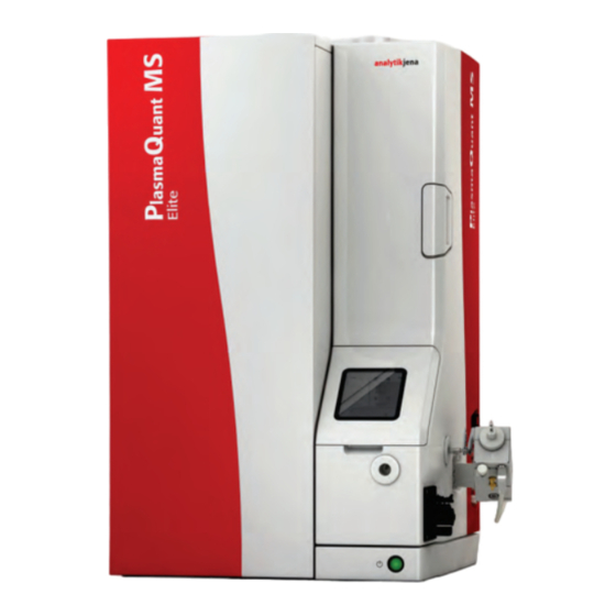
Summary of Contents for Endress+Hauser Analytik Jena PlasmaQuant MS Series
-
Page 1: Installation Guide
Installation Guide PlasmaQuant MS series ICP MS... - Page 2 Analytik Jena GmbH Manufacturer Konrad-Zuse-Str.1 07745 Jena Germany Phone + 49 3641 / 77 70 + 49 3641 / 77 92 79 Email info@analytik-jena.com Analytik Jena GmbH Service Konrad-Zuse-Str. 1 07745 Jena Germany Phone + 49 3641 / 77-7407 (Hotline) Email service@analytik-jena.com http://www.analytik-jena.com...
-
Page 3: Table Of Contents
PlasmaQuant MS Series Contents Contents Installation Guide ......................... 1 PlasmaQuant MS series ICP MS ..................1 Safety Practices and Hazards ..................5 Safety Messages and Symbols ................5 1.1.1 Warning Symbols ................... 6 Color Coding ......................6 Information Symbols ..................7 General Safety Hazards .................. - Page 4 Contents PlasmaQuant MS Series Instrument Tool Box ..................47 Connecting the Argon ..................47 Connecting the Mains Power ................48 6.5.1 Connecting the Instrument to Mains Power ..........49 Connecting the Exhaust Ducting ..............51 Connecting the Leybold SV40 PFPE Rotary Pump ......... 51 Installing the ASpect MS Software ..............
-
Page 5: Safety Practices And Hazards
PlasmaQuant MS Series Safety Practices and Hazards Safety Practices and Hazards The Analytik Jena PlasmaQuant MS (ICP-MS) and accessories have been carefully designed so that when used properly it is an accurate, fast, flexible, and safe analytical system. If the equipment is used in a manner not specified by the manufacturer, the protection provided by the equipment may be impaired. -
Page 6: Warning Symbols
Safety Practices and Hazards PlasmaQuant MS Series WARNING Indicates a potentially hazardous situation which might cause fatal or very serious injuries (deformities). CAUTION Indicates a potentially hazardous situation which might cause light or minor injuries. NOTICE Provides indications of potential material and environmental damage. Notes (without symbol or signal word) are used to give advice or additional information. -
Page 7: Information Symbols
PlasmaQuant MS Series Safety Practices and Hazards Information Symbols The following symbols appear on the ICP-MS instrument to provide additional information: Symbol Information Power ON Power OFF Fuse Single Phase Alternating Current (AC) Direct Current (DC) Indicates that the product complies with the requirements of one or more EU Directives OUT position of a bi-stable push switch IN position of a bi-stable push switch... -
Page 8: Electricity
Safety Practices and Hazards PlasmaQuant MS Series Shielding around the plasma compartment is designed to reduce UV, visible, and RF radiation to safe levels while still permitting easy access to the torch when maintenance is required. The spectrometer has an interlock system which is designed to extinguish the plasma if either plasma compartment latch is opened or if any of the cooling water, argon gas, or air flow rates drop below the required minimum level. -
Page 9: Compressed Gas
PlasmaQuant MS Series Safety Practices and Hazards 1.4.3 Compressed Gas All compressed gases (other than air) can create a hazard if they leak into the atmosphere. Even small leaks in gas supply systems can be dangerous. Any leak (except that of air) can result in an oxygen deficient atmosphere which can cause asphyxiation. -
Page 10: Heat, Ozone, Vapors, And Fumes
Safety Practices and Hazards PlasmaQuant MS Series In the event of a power failure, hydrogen gas may continue to flow from the supply even if the ICP-MS is completely off. Always manually shut off the hydrogen gas supply valve when there is no power to the ICP-MS. Instead of using pressurized gas cylinders as a source of hydrogen, consider using a hydrogen gas generator instead. -
Page 11: Radio Frequency Radiation
PlasmaQuant MS Series Safety Practices and Hazards Before attempting any maintenance on the sample introduction system, the field service engineer must be fully aware of all types of sample matrices and solvents that have been presented to the system. Field service engineers should wear rubber gloves to protect their hands whenever working on the sample introduction system. -
Page 12: Regulatory Compliance
Safety Practices and Hazards PlasmaQuant MS Series The instrument should never be moved or disturbed while the vacuum system is running. Never try to repair or replace an instrument component not described in the Manual without first consulting Analytik Jena or its authorized representative in your area. -
Page 13: Ce Compliance
PlasmaQuant MS Series Safety Practices and Hazards 1.6.3 CE Compliance The PQMS ICP-MS instrument has been designed to comply with the requirements of the Electro-Magnetic Compatibility (EMC) Directive and the Low Voltage (electrical safety) Directive (commonly referred to as the LVD) of the European Union. Analytik Jena has confirmed that each product complies with the relevant Directives by testing a prototype against the prescribed EN (European Norm), IEC, or CISPR standards. -
Page 14: Introduction
Introduction PlasmaQuant MS Series Introduction The information outlined in this publication is meant to provide systematic instructions for installing the ICP-MS. For details concerning installing compatible accessories, refer to the appropriate accessory operation or service manual. The ICP-MS system installation should only be performed by, and the instructions in this section are provided specifically for the guidance of, Analytik Jena Customer Support Representatives (CSRs) and authorized personnel who have successfully completed the ICP-MS service training course. -
Page 15: Installation Overview
PlasmaQuant MS Series Installation Overview Installation Overview The following points provide a brief systematic outline of the recommended installation procedure. Visually inspect the laboratory to confirm all pre-installation requirements have been satisfied. The instrument, accessories, and PC should be unpacked by inspection of Customer Support Engineer and positioned in the desired locations. -
Page 16: System Interconnection
System Interconnection PlasmaQuant MS Series System Interconnection Figure 4-1 ICP-MS System Interconnection... -
Page 17: Unpacking The Instrument
PlasmaQuant MS Series Unpacking the Instrument Unpacking the Instrument It is the customer’s responsibility to unpack the instrument, the accessories, and the kits and to inspect them for shipping damage before taking final acceptance from the deliverer. The pre-installation manual contains further information related to receiving, inspecting for shipping damage, and unpacking the instrument. -
Page 18: Shipping Kit
Unpacking the Instrument PlasmaQuant MS Series Shipping Kit The number of additional boxes shipped with the instrument will vary depending on the number of accessories and additional components ordered. The following items are included with every instrument: Item Part Number Software ASpect MS (10-5000-001-40) Instrument Logbook... - Page 19 PlasmaQuant MS Series Unpacking the Instrument Item Part Number USB cable (10-5008-001-91) USB Adapter (RS232) (11-011.605) Waste Bottle, 2 L (11-0515-029-10) Cooling Water Additive (13-410-540) (not included in normal shipment) Tuning Solution (10-405-810) (not included in normal shipment)
-
Page 20: Instrument Setup
Instrument Setup PlasmaQuant MS Series Instrument Setup Setting up the instrument involves installing the rotary pump, sample introduction system, water chiller, computer, and the tools. The printed factory test results and a CD containing the factory test worksheets are enclosed with the instrument logbook. Upon completion of the installation, insert these results in the customer’s instrument logbook for future reference. -
Page 21: Installing The Sample Introduction System
PlasmaQuant MS Series Instrument Setup Figure 6-3 Filling & Checking the Oil Level The mains voltage selection on the pumps is set to 240V during factory instrument testing. This is the correct setting independent of laboratory mains voltage. NOTICE The instrument AC input module distributes 200-240VAC to the vacuum pump, depending on the local mains electricity supply. -
Page 22: Installation Of The Torch
Instrument Setup PlasmaQuant MS Series 6.2.1 Installation of the torch 1. Fit one quick-connect fitting to each length of tubing. 2. Fit the quick-connect snap fitting to the other end of one length of tubing. Slide the fittings onto the torch. - Page 23 PlasmaQuant MS Series Instrument Setup 7. Close and lock the clamp arm: push the locking knob down and turn it 90-degrees until it clicks in place. 8. Connect the torch to the glass transfer tube with the glassware clamp. 9. Connect the plasma gas line (1) and the auxiliary gas line (2) to the fittings in the plasma compartment.
-
Page 24: Installation Of The Nebulizer
Instrument Setup PlasmaQuant MS Series 6.2.2 Installation of the nebulizer 1. Fit the gas and sample tubing to the nebulizer. Insert the capillary tubing connector directly onto the sample inlet of the nebulizer as far as it will go to minimize the dead space in the nebulizer (1). -
Page 25: Installation Of The Spray Chamber
PlasmaQuant MS Series Instrument Setup 6.2.3 Installation of the spray chamber 1. Attach a ~10cm piece of drain tubing to the waste outlet at the bottom of the spray chamber. 2. Open the holder assembly. Place the spray chamber into position in the lower half of the holder assembly. -
Page 26: Installation Of The Transfer Tube
Instrument Setup PlasmaQuant MS Series 6.2.4 Installation of the transfer tube WARNING Risk of eye and skin injuries due to UV and electromagnetic radiation! If you are using a non-standard sample introduction configuration, there may be a danger of direct exposure to UV or electromagnetic radiation from the opening in the side wall of the torch compartment. - Page 27 PlasmaQuant MS Series Instrument Setup 6. Connect the torch to the transfer tube with the glassware clamp. Note: Do not use conventional spherical joint clamps. These may cause signal stability problems. 7. If the spray chamber is already in place, fit the spherical joint of the glass transfer tube into the joint of the spray chamber and secure it using the glassware clamp.
-
Page 28: Installation Of The Peristaltic Pump Tubing
Instrument Setup PlasmaQuant MS Series 6.2.5 Installation of the peristaltic pump tubing CAUTION Risk of injury! Always switch off the peristaltic pump before installing or removing the pump tubing. Take care to keep loose clothing, jewelry, etc. clear of the pump while it is running. 1. - Page 29 PlasmaQuant MS Series Instrument Setup Nebulizer tubing Pressure bars Pump rollers Sample tubing - to be placed in the sample or the autosampler tubing Drain tubing from the spray chamber Figure 6-5 Peristaltic pump connections 6. Place the capillary that extends from the sample pump tubing into the sample or rinse solution.
- Page 30 Instrument Setup PlasmaQuant MS Series The addition of an Internal Standard is important in ICP-MS to account for physical Installation of the and matrix interferences. Internal Standards with multiple elements can be measured Internal Standard line over large mass ranges to account for mass bias effects. The inline addition of an Internal Standard minimizes sample preparation and is therefore often preferred.
-
Page 31: Installation Of The Aspq 3300 Autosampler
PlasmaQuant MS Series Instrument Setup 6.2.6 Installation of the ASPQ 3300 autosampler Connections at the autosampler Figure 6-8 Autosampler Overview Autosampler arm Wash cup Autosampler with cannula holder Wash cup pump Cannula 10 Speed controller for wash cup pump 4, 5 Rack for standards & QC solutions 11 Mains LED Base plate for racks 12 Sample aspiration tubing... - Page 32 Instrument Setup PlasmaQuant MS Series The autosampler is installed next to the PlasmaQuant MS. Between these two Installing the instruments 30 cm of clearance is required to allow space for opening the interface autosampler door. NOTICE The autosampler must not be connected to the mains during installation. 1.
- Page 33 PlasmaQuant MS Series Instrument Setup 3. Fit the racks for standards and QC solutions (1) in the base plate and attach the required sample racks (2). 4. Connect the pump tubing to the lower inlet connector (1a) of the wash cup. Clamp the tubing between two stoppers into the pump with the connection to the wash cup facing upwards.
- Page 34 Instrument Setup PlasmaQuant MS Series 8. Guide the sample capillary tubing initially in a loop through the hook on the cannula holder (1). 9. Thread the tubing from the left side through the hook (2) at the lower end of the head. 10.
-
Page 35: Installation Of The Cetac Asx-560 Autosampler
PlasmaQuant MS Series Instrument Setup 6.2.7 Installation of the CETAC ASX-560 autosampler Figure 6-10 Cetax ASX-560 Autosampler This guide shows common versions of the ASX-560 autosampler. Your autosampler Overview may have different racks, a different probe, or other minor differences from what is shown. - Page 36 Instrument Setup PlasmaQuant MS Series Autosampler Components Figure 6-11 Autosampler front view Figure 6-12 Autosampler back view Place the autosampler close to the ICP-MS or other analytical instrument. Place the Step 1: Choose a Location autosampler where space, liquid waste, and power requirements can be met.
- Page 37 PlasmaQuant MS Series Instrument Setup 1. Inspect all components for shipping damage. Step 2: Unpack the Autosampler 2. Place the tray on the autosampler base. 3. Mount the rinse station. The Z-drive moves the probe up and down. The Z-drive is shipped detached from the Step 3: Mount the Z- autosampler.
- Page 38 Instrument Setup PlasmaQuant MS Series Figure 6-15 Sliding the Z-Drive onto the Arm 4. Secure the Z-drive to the carriage using the two thumbscrews. Tighten the thumbscrews using your fingers. Figure 6-16 Securing the Z-Drive 5. Feed the cable through the rear guide block and around the rotor, then tighten the nut to secure the cable sleeve to the guide block.
- Page 39 PlasmaQuant MS Series Instrument Setup Figure 6-17 Guide Block with Nut 6. Turn the rotor clockwise as far as it will go. 7. Finish sliding the cable around the rotor on the back of the autosampler. Loosen the thumbscrew on the rotor to allow the cable to pass through the clamp, with about 2 mm of cable extending past the clamp.
- Page 40 Instrument Setup PlasmaQuant MS Series Figure 6-19 Z-Drive at Top Position with Gap 9. Hold the cable flat against the rotor and secure the cable by tightening thumbscrew on the rotor. The thumbscrew should be as tight as possible using just your fingers.
- Page 41 PlasmaQuant MS Series Instrument Setup Figure 6-21 Z-Drive Rotor If the rotor does not rotate freely, STOP and determine which part is sticking (see the Operator’s Manual). The simplest arrangement is for one channel of the peristaltic pump to supply rinse Step 4: Connect the Rinse solution to the rinse station, while the used rinse solution drains by gravity.
- Page 42 Instrument Setup PlasmaQuant MS Series Depending on your application, the waste rinse solution may be returned to the rinse solution container and recycled, or it may be directed to a separate waste container. 1. Verify that the supplied tubing material is compatible with the rinse solution you are using.
- Page 43 PlasmaQuant MS Series Instrument Setup 5. Use an appropriate length of the smaller ⅛ inch (3.2 mm) ID tubing to connect the rinse solution source to the fitting at the top of this channel. Figure 6-26 Connecting the Rinse Solution Source to the Pump 6.
- Page 44 Instrument Setup PlasmaQuant MS Series Step 5: Install the Sample Probe NOTICE To prevent contamination, wear gloves when handling the probe. 1. Shut down and unplug the autosampler. 2. Rotate the rotor on the back of the autosampler to move the Z-axis slider to the top of the Z-drive.
- Page 45 PlasmaQuant MS Series Instrument Setup Figure 6-30 Adjusting the Probe Height 6. Tighten the probe clamps. 7. Use the provided spiral wraps to secure the sample tube to the Z-drive cable. There should be just a little curve to the free sample tube when the probe is lowered, and an untangled loop when the probe is raised.
- Page 46 Instrument Setup PlasmaQuant MS Series One end of the sample transfer tubing is pre-connected to the sample probe. Step 6: Connect the Sample Tubing to the The tubing should be long enough to allow the sample probe to move easily to every PQMS position.
-
Page 47: Instrument Tool Box
PlasmaQuant MS Series Instrument Setup Serial Connection Connect the serial cable from the serial port on the host computer to the COM1 port on the autosampler. 1. Install the ASX Dashboard software from the CD. Step 9: Test the Connection 2. -
Page 48: Connecting The Mains Power
Instrument Setup PlasmaQuant MS Series Figure 6-34 Argon gas tubing Figure 6-35 Main Distribution Panel Showing Argon Inlet Connection 2. Connect the two-stage regulator to the supply outlet. 3. Use the adaptor provided in the shipping kit to connect the Swagelok fitting to the regulator output. -
Page 49: Connecting The Instrument To Mains Power
PlasmaQuant MS Series Instrument Setup Table 6-1 Requirements for the Single-Phase Instrument Mains Power Supply Options Mains Input Voltage Range Nominal Line Frequency Power (Load) Configuration ±5% Current ±1 Hz Single-phase, one 200-240 VAC 18 A Max. 50/60 Hz 3,600W Max outlet Ensure that the earth/ground pin on the mains receptacle/s is connected to a suitable mains earth/ground point. - Page 50 Instrument Setup PlasmaQuant MS Series relevant CSA and UL approvals. A mains power plug will be provided with each instrument; if it is not suitable for your installation, you will have to source the connector locally. Figure 6-37 Mains Input Cable and Connection Plug for US/Canada Figure 6-38 Mains Power Plugs for Australia/New Zealand (right) and UK/Europe (left) NOTE...
-
Page 51: Connecting The Exhaust Ducting
PlasmaQuant MS Series Instrument Setup Connecting the Exhaust Ducting 1. Retrieve the 100 mm exhaust tube clamp from the shipping kit supplied with the instrument. Figure 6-39 Fit the Exhaust Port to the Top of the Instrument 2. Slide the 100 mm diameter clamp over the 100mm diameter ducting and fit the ducting to the plasma exhaust port on the top of the instrument. - Page 52 Instrument Setup PlasmaQuant MS Series Figure 6-40 Leybold SV40 PFPE Rotary pump 3. Open the oil reservoir with a 12 mm Allen key (coming with the pump) 4. Check the level; it should be in the middle of “Min/Max” marks. 5.
-
Page 53: Installing The Aspect Ms Software
PlasmaQuant MS Series Instrument Setup An optional noise reduction cover is available. Installing the ASpect MS Software This section contains instructions for loading the Analytik Jena ASpect MS software. It is assumed the required operating system, such as Microsoft Windows 7, is already installed on the PC. - Page 54 Instrument Setup PlasmaQuant MS Series Figure 6-42 Setup language 5. When you see the Install Wizard, click Next. Figure 6-43 Install Wizard 6. On the License Agreement pop-up, choose “I accept the agreement” and click Next.
- Page 55 PlasmaQuant MS Series Instrument Setup Figure 6-44 License Agreement 7. Read the information and click Next. Figure 6-45 Information 8. Verify the destination folder and click Next.
- Page 56 Instrument Setup PlasmaQuant MS Series Figure 6-46 Verify the Destination Folder 9. Select the instrument model and components you want to install and click Next. Figure 6-47 Select Components Window 10. Select start menu folder and click Next.
- Page 57 PlasmaQuant MS Series Instrument Setup Figure 6-48 Start Menu Pop-Up Window 11. Select Additional Tasks and click Next. Figure 6-49 Additional Task Pop-Up Window 12. Click Install to finish the installation.
- Page 58 Instrument Setup PlasmaQuant MS Series Figure 6-50 Additional Task Pop-Up Window 13. Follow the instructions below:...
- Page 59 PlasmaQuant MS Series Instrument Setup 14. Click Finish button.
-
Page 60: Connecting The Pc And Loading The Usb Driver
Instrument Setup PlasmaQuant MS Series NOTE Installing the software in the default directory helps when offering future technical support. The software automatically creates shortcuts to the MS software on the desktop and the start menu. If shortcuts are NOT created, you need to do this at the end of the installation. - Page 61 PlasmaQuant MS Series Instrument Setup USB connection at rear of instrument Figure 6-51 Distribution Panel Showing USB Connection Port 2. Turn the PC on. 3. Turn the instrument on. When pushed in, the green button illuminates. This indicates that the instrument is on.
- Page 62 Instrument Setup PlasmaQuant MS Series Figure 6-53 New Hardware Pop-Up 5. Start the ASpect MS software. The following window appears prompting you to select an item from the table. Note that no items appear until the USB driver has been successfully loaded and the instrument is turned on. If the USB driver is working properly, communication to the instrument proceeds automatically.
-
Page 63: Enabling The Service Diagnostics Software
PlasmaQuant MS Series Instrument Setup Figure 6-55 ASpect MS start page Figure 6-56 Instrument Setup NOTE To better familiarize yourself with the ASpect MS software, you can click the Windows Start button and select Programs > ASpect MS Help. When the ASpect MS Help appears, select the How to link to view systematic instructions on how to use the ICP-MS instrument. -
Page 64: Connecting The Water Cooling System
Instrument Setup PlasmaQuant MS Series 2. Enter the service password “koala” at the login prompt. Access to the service diagnostics pages ceases each time the instrument module is closed. Figure 6-57 Enabling Service Diagnostics NOTE Typing “service” as the password provides access to the service pages of the instrument module, which is defined by a small key, illustrated on the page tab. - Page 65 PlasmaQuant MS Series Instrument Setup Inlet line Return line Figure 6-58 The Left Hose is the Inlet and the Right Hose is the Return 2. Connect the hoses to the water cooler and secure the hose clamps. NOTE Immersing the ends of the hoses in hot water makes them easier to fit to the hose barbs.
- Page 66 Instrument Setup PlasmaQuant MS Series Figure 6-59 Cooling water additive: A) Coragard CS 390 + B) AC-Bion 555 Permitted conductivity range G = 75 … 150 µS/cm Optimum conductivity range G = 100 … 120 µS/cm Required materials and reagents Chiller must be empty or drained to half of capacity.
- Page 67 PlasmaQuant MS Series Instrument Setup Figure 6-60 Enabling the Water Flow NOTE Initially you may need to repeat this procedure several times to clear the water lines of trapped air. Trapped air can cause the instrument to register a "water flow failure" condition, which results in the instrument automatically shutting off the water flow solenoid.
-
Page 68: Vacuum System Startup
Vacuum System Startup PlasmaQuant MS Series Vacuum System Startup Ensure that the customer’s extraction fan is on. 1. Click the Vacuum start up icon in the main toolbar. 2. Click Yes to start the vacuum. Refer to the status bar located on the bottom of the software pages to monitor pump-down progress. -
Page 69: Aspect Ms Software Setup
PlasmaQuant MS Series ASpect MS Software Setup ASpect MS Software Setup The Instrument optimization settings are different for every instrument and change over time, depending on usage and sample matrix. The ASpect MS software contains four default methods for calibration and testing the instrument. During a standard software installation, these methods, listed below, are stored in the following directory: C:\ProgramData\Analytik Jena\ASpect MS\Supplied Worksheets... - Page 70 ASpect MS Software Setup PlasmaQuant MS Series Figure 8-1 “Open” the System Setup files and “Save As” NOTE By saving the method with a date reference in the name, you can keep a record of the instrument’s setup parameters and performance test results over time, while keeping the original default worksheets as a reference.
-
Page 71: Instrument Optimization
PlasmaQuant MS Series Instrument Optimization Instrument Optimization The following summary outlines the recommended sequence for setting up the instrument for a performance test. Note that this sequence only works if the worksheets are set up to provide signal within specification (Reference chapter 8). ... - Page 72 Instrument Optimization PlasmaQuant MS Series NOTE If the plasma fails to light after several attempts, please refer to the instrument service manual “Plasma Generation” for troubleshooting procedures. With the plasma lit: 4. Open the Plasma Align tab of the Instrument Setup window. 5.
-
Page 73: Calibrations
PlasmaQuant MS Series Instrument Optimization Figure 9-1 Time Scan Displaying the Signal during Warm-Up NOTE Before starting, ensure that the worksheet selected for this scan has been updated with all the settings outlined in the factory test results and that the detector voltage is set in the detector setup page of the instrument module. -
Page 74: Plasma Alignment
Instrument Optimization PlasmaQuant MS Series NOTE Clicking the “Instrument” button on the main page of the software introduces the automated setup routine. Do not use the Auto-Setup routine for initial instrument installation calibrations. Conduct the following three functions from the designated individual tabs of the instrument setup module: ... -
Page 75: Resolution And Trim
PlasmaQuant MS Series Instrument Optimization Figure 9-3 Torch Alignment Manual alignment can be performed by deselecting the Automatic Alignment checkbox. Select either Horizontal or Vertical under Scan Type, and then press Start. Resolution and Trim The Resolution and Trim page is used to ensure peaks are the correct width for maximum signal intensity and minimal overlap, usually 0.80 AMU. - Page 76 Instrument Optimization PlasmaQuant MS Series Figure 9-4 Peak Resolution and Trim 1. Aspirate the 1ppb Tuning Solution. Resolution and Trim procedure 2. Go to the Resolution and Trim page of the Instrument Setup window. Make sure the Resolution (AMU) box is set to 0.80 3.
-
Page 77: Mass Calibration
PlasmaQuant MS Series Instrument Optimization Mass Calibration After performing a successful Resolution and Trim conduct the mass calibration routine. Ensure that the System Setup worksheet that was used for the plasma alignment and the Resolution and Trim is selected. The mass calibration routine calibrates the resolution for several isotopes (including 9Be, 25Mg, 59Co, 115In, 140Ce, 206Pb and 232Th). -
Page 78: Setting The Detector Voltage
Instrument Optimization PlasmaQuant MS Series Setting the Detector Voltage The software scans the detector voltage across the specified range, and recommends the ideal set point. When the detector voltage nears its maximum setting of 4kV, it needs to be replaced. Although the initial detector voltage is usually around 2.5kV, over time and with continued use, a detector ages and requires increased voltage to produce the same signal level from a given concentration of sample. - Page 79 PlasmaQuant MS Series Instrument Optimization NOTE If the From/To voltages are too close together or too far apart, an error message is generated. There must be enough scan range to create an “S”-shaped curve without over-ranging, and the From/To voltage ranges may need to be adjusted. Figure 9-6 Detector voltage calibration.
-
Page 80: Method Optimization
Method Optimization PlasmaQuant MS Series Method Optimization After completing the instrument warm-up period and the setup routine, optimization of ion optics and plasma settings might be required to obtain optimal performance. The ion optics and plasma settings required to produce optimal performance vary between instruments. - Page 81 PlasmaQuant MS Series Method Optimization Optimization parameter Typical setting Auxiliary gas 1.2 ± 0.15 L/min Nebulizer gas 1.00 ± 0.04 L/min Sheath gas 0.00 ± 0.00 L/min Sampling depth 5.5 ± 0.5 mm Pump speed 15 ± 5 rpm The effect each lens has on the sensitivity may change depending on the sensitivity optimization, however the interaction between the lenses remains the same.
- Page 82 Method Optimization PlasmaQuant MS Series Ion optics Effect of lens on Range Tuning tips for the operator elements sensitivity (Volts) Extraction lens Moderate to sharp -1000 to 0 In normal sensitivity mode extraction lens #2 has a sharper effect on the sensitivity than when in high-sensitivity mode. Typically, the extraction lens #2 voltage setting is more negative than the #1 setting.
-
Page 83: Optimizing The Ion Optics
PlasmaQuant MS Series Method Optimization 10.2 Optimizing the Ion Optics Tuning the ICP-MS to an optimum analytical performance often requires an experienced operator, and it is usually a time-consuming task. The auto optimization developed in the ASpect MS software provides fully-automated optimization of ion- optics. - Page 84 Method Optimization PlasmaQuant MS Series Figure 10-1 Selecting an Automatic Optimization Routine 3. Verify that the selected optimization routine is appropriate. There are numerous routines for ion optics, standard mode, high performance mode and iCRC mode. In most cases, running only the ion optics optimization should be enough; the plasma conditions should not change much unless you have switched nebulizers or cones.
-
Page 85: Method Optimization Troubleshooting
PlasmaQuant MS Series Method Optimization The automatic optimization ends when the best settings are found or the maximum time is reached (20 minutes for ion optics). Optimization can also be stopped early; the best settings found to that point are used. Close the optimization window. -
Page 86: Performance
Performance PlasmaQuant MS Series Performance The performance tests not only provide a thorough indication of the instrument analytical performance but also are an excellent diagnostic tool. Performance test results, worksheet data, and the instrument settings are invaluable in understanding what maintenance is required and if a there is a hardware fault. It is important that each part of the calibration and testing routine is conducted with the same method. -
Page 87: Background
PlasmaQuant MS Series Performance Table 11-1 Sensitivity specs for PQMS instruments Isotope Sensitivity Sensitivity on time scan when using 1 ppb (c/s/ppm) solution > 20 x 10 > 2 x 10 > 500 x 10 > 5 x 10 > 300 x 10 >... -
Page 88: Precision (Rsd %)
Performance PlasmaQuant MS Series 11.1.5 Precision (RSD %) Stability of ICP-MS measurements are assessed by taking the standard deviation of successive replicates in a single measurement. This is expressed as %RSD of the analyte signal based on a 20 minute per solution, 10 replicate per sample test. Specification PQMS &... -
Page 89: Boost Check
PlasmaQuant MS Series Performance Figure 11-2 He iCRC check 11.1.8 Boost Check Note: Only valid with ASpect MS version 4.xx or later in Elite model only. The voltage range is limited between 0-10 V. The test below was realized until 22 V with R&D instrument. -
Page 90: Test Solutions
Performance PlasmaQuant MS Series 9. All signals must be stable and changing fast (within seconds). 10. Use the same process to test Skimmer bias with full He gas flow 200ml/min. Make sure the results similar to the Figure 11-4. Print the pages for H and He BOOST test (Figure 11-3 and Figure 11-4). - Page 91 PlasmaQuant MS Series Performance NOTE Chlorides, sulphides, phosphates, and sulphates should be avoided in preparation of tuning solutions). Bulk solution should be diluted using distilled, de-ionized (> 10 MΏ) water and ). This solution must not acidified to 1% with ultra-high-purity nitric acid (HNO contain more than 0.1 ppb Ca, Ti, Cd, Mo, Zr, La, Sn, Gd, Dy, Ga, Cr, Sm, or W.
-
Page 92: Appendix A - Routine Maintenance
Appendix A - Routine Maintenance PlasmaQuant MS Series Appendix A - Routine Maintenance Copy this page, complete the checklist, and insert it into the instrument logbook. Routine Maintenance – Operator Checklist Check Component Action Frequency Torch Check for verification and Weekly or as required surface coating of sample depending on sample matrix...
Need help?
Do you have a question about the Analytik Jena PlasmaQuant MS Series and is the answer not in the manual?
Questions and answers